
Related Manuals for Fluke Reliable Power Meters 1941


Summary of Contents for Fluke Reliable Power Meters 1941
- Page 1 ® Multipoint Power Recorder Installation Guide PN 2010675 December 2003 Rev.3, 1/04 © 1999, 2000, 2004 Fluke Corporation. All rights reserved. Printed in USA All product names are trademarks of their respective companies.
- Page 3 The Multipoint Power Recorder is for use by WARNING qualified personnel only. Do not install the Multipoint on a power line unless you are qualified to do so. High voltages that can cause burns and lethal shocks are present during power monitoring.
- Page 4 This equipment has been tested and found to RADIO comply with the limits for a Class A digital device, INTERFERENCE pursuant to Part 15 of the FCC Rules. These limits are designed to provide reasonable protection STATEMENT against harmful interference when the equipment is INFORMATION operated in a commercial environment.
- Page 5 Trademark Information The "r" logo and InSite Power Recorder are registered trademarks of Fluke Corporation. Reliable Power Meters, Full Disclosure, PR/Link, Scenario, and Power Recorder are trademarks of Fluke Corporation. Technical Support For technical support, contact Fluke Power Quality at:...
-
Page 6: Table Of Contents
Table of Contents Preface ................. vi Warning Symbols on the Multipoint Power Recorder ....vi Introducing the Multipoint Power Recorder ....... 1 Before You Install..............4 Installing the Multipoint Power Recorder......5 Installing the Multipoint with Acquisition Unit Model 1941 or 1948 .................. 6 Overview of the Installation Process ..........6 De-energizing Relevant Power............7 Mounting the Multipoint Base Unit ..........8... - Page 7 Confirming Connections and Finishing Up...... 34 Check the Range Lights (LEDs) for Current.........34 Check the Range Lights (LEDs) for Each Voltage.......35 Make Sure Voltage Phases and Current Phases are Paired Correctly ..................35 Checking Connections Through Software ........35 Checking Voltage and Current Pairing..........36 Checking for Ground and Neutral Current Connections....36 Configuring the Multipoint ...............37 Finishing Up..................38...
-
Page 8: Preface
Preface This guide describes the Multipoint Power Recorder and tells you how to install it and connect it to power. After installation you will need to connect it to a computer running either the Power Recorder System Software or the Scenario software, and then configure the Multipoint. -
Page 9: Introducing The Multipoint Power Recorder
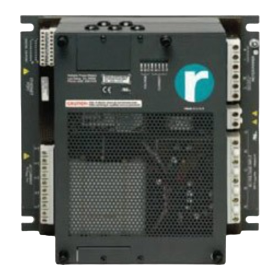
Introducing the Multipoint Power Recorder The Multipoint Power Recorder is designed for permanent or semi- permanent installation of a Power Recorder in a non-hostile environment. The Multipoint provides the same quality and features of other Reliable Power Meters power recorders at a lower cost. Lethal voltages are present. - Page 10 Introducing the Multipoint Recorder The Multipoint Base Unit Guide pins slide into the back of the Acquisition Unit. The Multipoint Acquisition Unit These thumb screws are used to tighten the Acquisition Unit onto the Base Unit.
- Page 11 Introducing the Multipoint Recorder Combining the Base and Acquisition Units The Multipoint System Front View (Factory use only. DO NOT Safety ground connect.) Reliable Power Meters Los Gatos, CA 95032 Meter power Phone (408) 358-5100 connection Ethernet Risk of electric shock, do not remove cover. CAUTION Made in U.S.A Refer servicing to qualified service personnel.
-
Page 12: Before You Install
Installing the Multipoint: Before You Install Before You Install Installation Considerations Before installing your Multipoint Power Recorder, be sure to consider the following: 1. Location: The Multipoint Power Recorder must be installed according to applicable electrical codes. When choosing an installation location, keep in mind that you may need to supply a suitable enclosure, conduit, and other materials. -
Page 13: Installing The Multipoint Power Recorder
Installing the Multipoint with Acquisition Unit Model 1941 or 1948 Installing the Multipoint Power Recorder Acquisition Unit Models 1941 , 1948* To install the Multipoint Power Recorder with Acquisition Unit 1941 or 1948, follow the instructions on pages 6 through 19. You use these units with the CTs embedded in the Base Unit. -
Page 14: Installing The Multipoint With Acquisition Unit Model 1941 Or 1948
Installing the Multipoint with Acquisition Unit Model 1941 or 1948 Installing the Multipoint with Acquisition Unit Model 1941 or 1948 Overview of the Installation Process To install the Multipoint Power Recorder with either Acquisition Unit model 1941 or 1948, follow the process described below. Each of the steps in this process is described in detail on the next pages (pages 7 through 19). -
Page 15: De-Energizing Relevant Power
Installing the Multipoint with Acquisition Unit Model 1941 or 1948 Finish up. (See pages 34-38.) Note: Mounting hardware and connection wires are not included. In addition to being physically installed at a BEFORE YOU facility, the Multipoint Power Recorder also needs CAN USE AN configured to be... -
Page 16: Mounting The Multipoint Base Unit
Installing the Multipoint with Acquisition Unit Model 1941 or 1948 Mounting the Multipoint Base Unit The Multipoint Base Unit must be mounted to a support adequate to support its weight (18.5 pounds/8.39 kg). Use the Multipoint Template included in the package to mark where you need to drill holes on the support panel. -
Page 17: Connecting The Safety Ground
Installing the Multipoint with Acquisition Unit Model 1941 or 1948 Connecting the Safety Ground Connect the ground first. Screw the ground wire securely to the Safety ground stud. Safety ground Reliable Power Meters Los Gatos, CA 95032 Phone (408) 358-5100 Risk of electric shock, do not remove cover. -
Page 18: Connecting To The Meter Power Source
Installing the Multipoint with Acquisition Unit Model 1941 or 1948 Connecting to the Meter Power Source Warning: Before connecting the Multipoint Power Recorder to a power source the ground wire should be securely screwed to the Safety ground stud. You can connect to the Multipoint meter power using either AC or DC. - Page 19 Installing the Multipoint with Acquisition Unit Model 1941 or 1948 To hook up power to the Multipoint Power Recorder Make the connection between the power source and the meter power terminal strip on the Multipoint Base Unit. For an AC connection, For a DC connection, connect the connect line and neutral, , positive and negative terminals, as...
-
Page 20: Connecting To Voltage
Installing the Multipoint with Acquisition Unit Model 1941 or 1948 Connecting to Voltage WARNING: Make sure that all equipment, wiring, and connections are de-energized before proceeding. Note: All connections should be wired in accordance with local electrical codes. Starting at the Multipoint unit, attach the voltage wires to the voltage measurement terminal strip on the Multipoint Base Unit. - Page 21 Installing the Multipoint with Acquisition Unit Model 1941 or 1948 Reliable Power Meters Los Gatos, CA 95032 Phone (408) 358-5100 Risk of electric shock, do not remove cover. CAUTION Made in U.S.A Refer servicing to qualified service personnel. Front View Attach the voltage wires to the voltage measurement terminal strip.
-
Page 22: Connecting To Current
Installing the Multipoint with Acquisition Unit Model 1941 or 1948 Connecting to Current Following are instructions for connecting a Multipoint Base Unit to a permanently installed CT with a 5 Amp secondary. For other applications, consult with Reliable Power Meters’ Customer Service. Note: If you’re using an Acquisition Unit model 1942 or 1949 for use with Reliable Power Meter current clamps, be sure to follow the instructions on pages 20 to 33. -
Page 23: Wiring Diagrams
Installing the Multipoint with Acquisition Unit Model 1941 or 1948 Reliable Power Meters Los Gatos, CA 95032 Phone (408) 358-5100 Risk of electric shock, do not remove cover. CAUTION Made in U.S.A Refer servicing to qualified service personnel. Front View Attach the current wires of the secondary to the current measurement terminal strip. -
Page 24: Connecting Ethernet
Installing the Multipoint with Acquisition Unit Model 1941 or 1948 Connecting Ethernet Plug a standard Category 5 RJ45 terminated Ethernet patch cable into the Ethernet port on the Multipoint Base Unit. Note: These connections are for factory use only. Side View Ethernet connection Reliable Power Meters Los Gatos, CA... -
Page 25: Checking Connections Before Restoring Power
Installing the Multipoint with Acquisition Unit Model 1941 or 1948 the Multipoint Power Recorder and the other end into your computer. An Ethernet wiring diagram is provided in Appendix D. If you need additional information about proper wiring of Ethernet, consult your network administrator. -
Page 26: Putting The Acquisition Unit In Place
Installing the Multipoint with Acquisition Unit Model 1941 or 1948 Putting the Acquisition Unit in Place Slide the Acquisition Unit onto the Base Unit, using the guide pins for proper blind mate connection. Thumbscrew Guide pin Tighten the four thumbscrews to secure the Acquisition Unit in position. -
Page 27: What Next
Installing the Multipoint with Acquisition Unit Model 1941 or 1948 Notice the power-on sequence of lights as the unit performs a self- test. All lights blink on, then off. In sequence, the individual lights turn on-off, from left to right. Finally, the lights remain on or off in accordance with the amount of voltage and current applied. -
Page 28: Installing The Multipoint With Acquisition Unit Model 1942 Or 1949
Installing the Multipoint with Acquisition Unit Model 1942 or 1949 Installing the Multipoint with Acquisition Unit Model 1942 or 1949 Overview of the Installation Process To install the Multipoint Power Recorder with either Acquisition Unit 1942 or 1949 for use with Reliable Power Meter current clamps, follow the process described below. -
Page 29: De-Energizing Relevant Power
Installing the Multipoint with Acquisition Unit Model 1942 or 1949 Put the Multipoint Acquisition Unit in place. (See page 30.) Connect the Multipoint Acquisition Unit to current. (See page 32.) Finish up. (See pages 34-38.) Note: Mounting hardware and connection wires are not included. In addition to being physically installed at a BEFORE YOU facility, the Multipoint also needs to be... -
Page 30: Mounting The Multipoint Base Unit
Installing the Multipoint with Acquisition Unit Model 1942 or 1949 Mounting the Multipoint Base Unit The Multipoint Base Unit must be mounted to a support adequate to support its weight (18.5 pounds/8.39 kg). Use the Multipoint Template included in the package to mark where you need to drill holes on the support panel. -
Page 31: Connecting The Safety Ground
Installing the Multipoint with Acquisition Unit Model 1942 or 1949 Connecting the Safety Ground Connect the ground first. Screw the ground wire securely to the Safety ground stud. Safety ground Reliable Power Meters Los Gatos, CA 95032 Phone (408) 358-5100 Risk of electric shock, do not remove cover. -
Page 32: Connecting To The Meter Power Source
Installing the Multipoint with Acquisition Unit Model 1942 or 1949 Connecting to the Meter Power Source Warning: Before connecting the Multipoint Power Recorder to a power source the ground wire should be securely screwed to the Safety ground stud. You can connect to the Multipoint meter power using either AC or DC. - Page 33 Installing the Multipoint with Acquisition Unit Model 1942 or 1949 To hook up power to the Multipoint recorder Make the connection between the power source and the meter power terminal strip on the Multipoint For an AC connection, For a DC connection, connect the connect line and neutral, as positive and negative terminals, as labeled.
-
Page 34: Connecting To Voltage
Installing the Multipoint with Acquisition Unit Model 1942 or 1949 Connecting to Voltage WARNING: Make sure that all equipment, wiring, and connections are de-energized before proceeding. Note: All connections should be wired in accordance with local electrical codes. Starting at the Multipoint unit, attach the voltage wires to the voltage measurement terminal strip on the Multipoint Base Unit. -
Page 35: Wiring Diagrams
Installing the Multipoint with Acquisition Unit Model 1942 or 1949 Reliable Power Meters Los Gatos, CA 95032 Phone (408) 358-5100 Risk of electric shock, do not remove cover. CAUTION Made in U.S.A Refer servicing to qualified service personnel. Front View Attach the voltage wires to the voltage measurement terminal strip. - Page 36 Installing the Multipoint with Acquisition Unit Model 1942 or 1949 Connecting Ethernet Plug a standard Category 5 RJ45 terminated Ethernet patch cable into the Ethernet port on the Multipoint Base Unit. Note: These connections are for factory use only. Side View Ethernet connection Reliable Power Meters Los Gatos, CA...
-
Page 37: Checking Connections Before Restoring Power
Installing the Multipoint with Acquisition Unit Model 1942 or 1949 the Multipoint Power Recorder and the other end into your computer. An Ethernet wiring diagram is provided in Appendix D. If you need additional information about proper wiring of Ethernet, consult your network administrator. -
Page 38: Putting The Acquisition Unit In Place
Installing the Multipoint with Acquisition Unit Model 1942 or 1949 Putting the Acquisition Unit in Place Slide the Acquisition Unit onto the Base Unit, using the guide pins for proper blind mate connection. Thumbscrew Guide pin Tighten the four thumbscrews to secure the Acquisition Unit in position. - Page 39 Installing the Multipoint with Acquisition Unit Model 1942 or 1949 Notice the power-on sequence of lights as the unit performs a self- test. All lights blink on, then off. In sequence, the individual lights turn on-off, from left to right. Finally, the lights remain on or off in accordance with the amount of voltage and current applied.
-
Page 40: Connecting To Current Using Reliable Power Meter Current Clamps
Installing the Multipoint with Acquisition Unit Model 1942 or 1949 Connecting to Current Using Reliable Power Meter Current Clamps Acquisition Unit Models 1942 and 1949 have external connections for use with Reliable Power Meter current clamps. You connect RPM Current clamps to these external connections on units 1942 and 1949. -
Page 41: What Next
Installing the Multipoint with Acquisition Unit Model 1942 or 1949 Attach the current clamps to the Multipoint Acquisition Unit. If you’re using flexible clamps, attach the clamps directly to the Multipoint Acquisition Unit. Attach each clamp to the appropriately labeled connection on the front end of the Multipoint acquisition unit. -
Page 42: Confirming Connections And Finishing Up
Checking Connections and Finishing Up Confirming Connections and Finishing Up After connecting the Multipoint, check to be sure that the Multipoint is registering both current and voltage and check to be sure the voltage and current are paired correctly, as described below. Check the Range Lights (LEDs) for Current The Multipoint contains range lights for each current connection. -
Page 43: Check The Range Lights (Leds) For Each Voltage
Checking Connections and Finishing Up Check the Range Lights (LEDs) for Each Voltage The connection panel on the Multipoint contains range lights for each phase that indicate when a connection is established. When the light is ON, you know that the connection is secure and that voltage is present. -
Page 44: Checking Voltage And Current Pairing
Checking Connections and Finishing Up Link to the Multipoint from the Power Recorder System Software. If the Multipoint has not yet been configured, use the configuration settings to designate the correct power type. Open the Scope view. Checking Voltage and Current Pairing Open the Scope Phasor window. -
Page 45: Configuring The Multipoint
Checking Connections and Finishing Up Click the Magnify tool to zoom in and inspect the current trace. Tip: You can also change the Full Scale settings from the Option menu. Configuring the Multipoint While you are linked to the Multipoint, you can configure it, to set power type and other parameters. -
Page 46: Finishing Up
Checking Connections and Finishing Up Finishing Up Before you finalize the installation, double-check these connections: Make sure that all wires are neatly routed and secured. Be sure to provide adequate strain relief for wires going to the terminal blocks. Check to see whether voltage and current wires are paired correctly. -
Page 47: Appendix A. Multipoint Specifications
Appendices Appendix A. Multipoint Specifications Measurement Parameters Voltage Four (4) Channels: Input: 100 millivolts to 600 V max. Accuracy: ± 1% of reading (typically 0.5%) Impulses: 100 volts peak to 6400 Volts peak ± 2% of full scale. (available only on the high-speed Acquisition unit, model # 1948) Impedance: 2 megohms to ground... - Page 48 Appendices Power Requirements 100 - 240 V , 50/60 Hz 10 - 15 VDC 40 VA Max. Dimensions Size: 12.39" x 11.56" x 6.0" (31.47 cm x 29.36 cm x 15.24 cm) Weight: 18.5 pounds (8.39 kg) Environmental Requirements For use indoors or in a suitable, protective enclosure outdoors. Maximum Altitude: 2000 meters Operating: 0°...
- Page 49 Appendices Cleaning or Decontamination Instructions After removing power from unit, a damp cloth may be used to remove dust particles that may have accumulated on the surface of the instrument. Fuses Used In the Product There are no operator accessible fuses in the Reliable Power Meter. Fuse replacement must be performed by service personnel using IEC acceptable fuses.
-
Page 50: Appendix B. Current Clamps
Appendices Appendix B. Current Clamps The clamps listed below are for use with Acquisition Unit Models 1942 or 1949 but are not included as part of those models. They are available for purchase separately through Reliable Power Meters. Current Range Current Clamp and Opening Size Uses... - Page 51 Appendices Current Range Current Clamp and Opening Size Uses 1 Amp to 3000 Connecting to high Amps currents with busbars or large Jaw opening 1.97” wires. x 5.31” 3000 Amp (# 3300 and # 3000R*) 2 Amp to 100 Getting around Amps cable bundles and large busbars.
- Page 52 Appendices Current Range Current Clamp and Opening Size Uses 100 Amp to 5000 Getting around Amps cable bundles and large busbars. Flexible current transformer, 48” long. 5000 Amp (# 3312) 10 Amp current Permanent transformer, split- installation around core (red). previously installed wiring.
-
Page 53: Appendix C. Wiring Diagrams
Appendices Appendix C. Wiring Diagrams Single-Phase SINGLE PHASE GROUND ETHERNET 10-15 Vdc, 40W Reliable Power Meters Negative Ground Los Gatos, CA 95032 Phone (408) 358-5100 100-240V NEUTRAL Risk of electric shock, do not remove cover. CAUTION Made in U.S.A Refer servicing to qualified service personnel. 40VA max. - Page 54 Appendices Split Single-Phase SPLIT PHASE GROUND ETHERNET 10-15 Vdc, 40W Reliable Power Meters Negative Ground Los Gatos, CA 95032 Phone (408) 358-5100 100-240V NEUTRAL Risk of electric shock, do not remove cover. CAUTION Made in U.S.A Refer servicing to qualified service personnel. 40VA max.
- Page 55 Appendices 4 Wire Wye (3-Phase Wye with ground) 4 WIRE WYE GROUND ETHERNET 10-15 Vdc, 40W Reliable Power Meters Negative Ground Los Gatos, CA 95032 Phone (408) 358-5100 100-240V NEUTRAL Risk of electric shock, do not remove cover. CAUTION Made in U.S.A Refer servicing to qualified service personnel.
- Page 56 Appendices 3-Phase Delta DELTA GROUND ETHERNET 10-15 Vdc, 40W Reliable Power Meters Negative Ground Los Gatos, CA 95032 Phone (408) 358-5100 100-240V NEUTRAL Risk of electric shock, do not remove cover. CAUTION Made in U.S.A Refer servicing to qualified service personnel. 40VA max.
-
Page 57: Appendix D. Ethernet Wiring
Appendices Appendix D. Ethernet Wiring CAUTION: Networking is a specialized field. The information provided below is a wiring snapshot only and is not intended to provide complete instructions. If you are creating your own cables, make sure you understand how to make them correctly. If you are uncertain about any aspect of creating networking cables, use a network cable installation contractor or expert, or contact your network administrator. - Page 58 Fluke Corporation P.O. Box 9090 Everett, WA 98206 USA USA: (800) 443-5853 Europe/Middle East/Africa: +31(0)40 2 675 200 Canada: (800) 363-5853 Other countries: (425) 446-5500 http://www.fluke.com...
Need help?
Do you have a question about the Reliable Power Meters 1941 and is the answer not in the manual?
Questions and answers