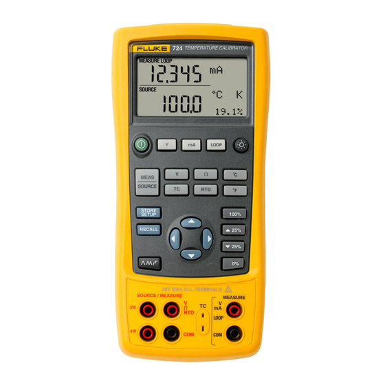
Fluke 724 User Manual
Temperature calibrator
Hide thumbs
Also See for 724:
- Calibration manual (76 pages) ,
- User manual (56 pages) ,
- Specifications (1 page)

Subscribe to Our Youtube Channel
Related Manuals for Fluke 724


Summary of Contents for Fluke 724
- Page 1 ® Temperature Calibrator Users Manual February 2000 Rev.1, 8/03 © 2000-2003 Fluke Corporation. All rights reserved. All product names are trademarks of their respective companies.
- Page 2 Parts, product repairs and services are warranted for 90 days. This warranty extends only to the original buyer or end-user customer of a Fluke authorized reseller, and does not apply to fuses, disposable batteries or to any product which, in Fluke’s opinion, has been misused, altered, neglected, contaminated, or damaged by accident or abnormal conditions of operation...
-
Page 3: Table Of Contents
Table of Contents Title Page Introduction........................1 Contacting Fluke......................1 Standard Equipment ...................... 3 Safety Information......................3 Getting Acquainted with the Calibrator ................8 Input and Output Terminals ..................8 Keys .......................... 10 Display ........................13 Getting Started ......................14 Shut Down Mode ...................... - Page 4 Users Manual Using Resistance-Temperature Detectors (RTDs) ..........23 Using Source Mode......................26 Sourcing Electrical Parameters ................. 26 Simulating Thermocouples ..................27 Simulating RTDs......................27 Setting 0 % and 100 % Output Parameters ..............30 Stepping and Ramping the Output................. 30 Manually Stepping the Output ...................
- Page 5 Temperature Calibrator Contents (continued) General Specifications ....................43 Index ............................45...
- Page 6 Users Manual...
- Page 7 List of Tables Table Title Page Summary of Source and Measure Functions................ 2 International Symbols ......................7 Input/Output Terminals and Connectors ................9 Key Functions ........................11 Thermocouple Types Accepted .................... 21 RTD Types Accepted......................24 Replacement Parts ....................... 37...
- Page 8 Users Manual...
- Page 9 List of Figures Figure Title Page Standard Equipment ......................6 Input/Output Terminals and Connectors ................8 Keys............................10 Elements of a Typical Display....................13 Voltage-to-Voltage Test ......................15 Adjusting the Contrast ......................16 Measuring Voltage and Current Output ................17 Connections for Supplying Loop Power................
- Page 10 Users Manual viii...
-
Page 11: Introduction
Your Fluke 724 Temperature Calibrator is a handheld, To order accessories, receive operating assistance, or battery-operated instrument that measures and sources a get the location of the nearest Fluke distributor or Service variety of thermocouples and RTDs. See Table 1. Center, call:... - Page 12 Users Manual Table 1. Summary of Source and Measure Functions Function Measure Source dc V 0 V to30 V 0 V to10 V Resistance to 3200 to 3200 Thermocouple Types E, J, K, T, B, R, S, L, U, N, mV Pt100 (385) (Resistance-...
-
Page 13: Standard Equipment
Temperature Calibrator Standard Equipment Standard Equipment Safety Information The items listed below and shown in Figure 1 are included The calibrator is designed in accordance with IEC1010-1, with your calibrator. If the calibrator is damaged or ANSI/ISA S82.01-1994 and CAN/CSA C22.2 No. 1010.1- something is missing, contact the place of purchase 92. - Page 14 Users Manual W Warning To avoid possible electric shock or personal injury: Do not apply more than the rated voltage, as marked on the calibrator, between the terminals, or between any terminal and earth ground. Maximum for all terminals is 30 V, 24 mA. Before each use, verify the calibrator’s operation by measuring a known voltage.
- Page 15 Temperature Calibrator Safety Information W Warning Use only 4 AA batteries, properly installed in the calibrator case, to power the calibrator. Disconnect test leads before changing to another measure or source function. When servicing the calibrator, use only specified replacement parts. To avoid false readings, which could lead to possible electric shock or personal injury, replace the batteries as soon as the battery indicator (M) appears.
- Page 16 Users Manual Alligator Clips TL75 Test Lead Set Stackable Test Leads zi01f.eps Figure 1. Standard Equipment...
- Page 17 Temperature Calibrator Safety Information Table 2. International Symbols AC - Alternating current Double insulated DC - Direct current Battery Earth ground Refer to the manual for information about this feature. Pressure ON/OFF Conforms to Canadian Standards Conforms to European Union directives Association directives...
-
Page 18: Getting Acquainted With The Calibrator
Users Manual Getting Acquainted with the Calibrator Input and Output Terminals TEMPERATURE CALIBRATOR Figure 2 shows the calibrator input and output terminals. Table 3 explains their use. LOOP ˚ MEAS SOURCE ˚ STORE 100% SETUP RECALL zi02f.eps Figure 2. Input/Output Terminals and Connectors... - Page 19 Temperature Calibrator Getting Acquainted with the Calibrator Table 3. Input/Output Terminals and Connectors Name Description MEASURE V, mA Input terminals for measuring voltage, current, and supplying loop power. terminals TC input/output Terminal for measuring or simulating thermocouples. This terminal accepts a miniature polarized thermocouple plug with flat, in-line blades spaced 7.9 mm (0.312 in) center to center.
-
Page 20: Keys
Users Manual Keys Figure 3 shows the calibrator keys and Table 4 explains their use. TEMPERATURE CALIBRATOR TEMPERATURE CALIBRATOR LOOP LOOP ˚ ˚ MEAS MEAS SOURCE SOURCE ˚ ˚ STORE STORE 100% 100% SETUP SETUP RECALL RECALL 30V MAX ALL TERMINALS 30V MAX ALL TERMINALS SOURCE / MEASURE SOURCE / MEASURE... - Page 21 Temperature Calibrator Getting Acquainted with the Calibrator Table 4. Key Functions Name Description Turns the power on or off. Selects voltage measurement function in the upper display. Selects the mA measurement function in the upper display. Activates a 24-volt loop supply while measuring mA. Turns backlight on or off.
- Page 22 Users Manual Table 4. Key Functions (cont.) Name Description Cycles through : Slow repeating 0 % - 100 % - 0 % ramp Fast repeating 0 % - 100 % - 0 % ramp Repeating 0 % - 100 % - 0 % ramp in 25 % steps Disables Shut Down Mode Enables Shut Down Mode Increases or decreases the source level.
-
Page 23: Display
Temperature Calibrator Getting Acquainted with the Calibrator Display Figure 4 shows the elements of a typical display. Memory Locations Loop Annunciator for Calibrator Setups Low Battery Symbol Units Display Mode Indicator Auto Ramp sh07f.eps Figure 4. Elements of a Typical Display... -
Page 24: Getting Started
Users Manual Press to increase the output to 5 V. Press and Getting Started hold to enter 5 V as the 100 % value. This section acquaints you with some basic operations of the calibrator. Press to step between 0 and 100 % in 25 % step increments. - Page 25 Temperature Calibrator Shut Down Mode zi04f.eps Figure 5. Voltage-to-Voltage Test...
-
Page 26: Contrast Adjustment
Users Manual Contrast Adjustment Note Available with V2.1 Firmware or greater. To identify firmware version, press and hold J TEMPERATURE CALIBRATOR when powering up. The firmware version will be shown in the upper units display for about 1 second after initialization. To adjust the contrast, proceed as follows: LOOP Press... -
Page 27: Using Measure Mode
Temperature Calibrator Using Measure Mode Using Measure Mode Measuring Electrical Parameters (Upper Display) To measure the current or voltage output of a transmitter, TEMPERATURE CALIBRATOR use the upper display and proceed as follows: Press to select current. LOOP should not be on. Connect the leads as shown in Figure 7. - Page 28 Users Manual TEMPERATURE CALIBRATOR LOOP ˚ MEAS SOURCE ˚ TEST DC PWR – + – STORE 100% SETUP RECALL – Black zi06f.eps Figure 8. Connections for Supplying Loop Power...
-
Page 29: Measuring Electrical Parameters (Lower Display)
Temperature Calibrator Using Measure Mode Measuring Electrical Parameters (Lower Display) To measure the electrical parameters using the lower display, proceed as follows: Connect the calibrator as shown in Figure 9. TEMPERATURE CALIBRATOR If necessary, press for MEASURE mode (lower display) Press for dc voltage or current, or resistance. -
Page 30: Measuring Temperature
Users Manual Note Measuring Temperature One pin is wider than the other. Do not try to Using Thermocouples force a miniplug in the wrong polarization. The calibrator supports ten standard thermocouples, If the calibrator and the thermocouple plug are at including types E, N, J, K, T, B, R, S, L, or U. - Page 31 Temperature Calibrator Using Measure Mode Table 5. Thermocouple Types Accepted Positive Lead (H) Type Positive Lead Color Negative Lead Specified Range Material Material ( C) ANSI* IEC** Chromel Purple Violet Constantan -200 to 950 Ni-Cr-Si Orange Pink Ni-Si-Mg -200 to 1300 Iron White Black...
- Page 32 Users Manual 30V MAX ALL TERMINALS SOURCE / MEASURE MEASURE Process Temperature LOOP Warning 30 V maximum to TC Miniplug zi14f.eps Figure 10. Measuring Temperature with a Thermocouple...
-
Page 33: Using Resistance-Temperature Detectors (Rtds)
Temperature Calibrator Using Measure Mode Using Resistance-Temperature Detectors (RTDs) To measure temperature using an RTD input, proceed as follows: The calibrator accepts RTD types shown in Table 6. RTDs If necessary, press for MEASURE mode. are characterized by their resistance at 0 °C (32 °F), which is called the “ice point”... - Page 34 Users Manual Table 6. RTD Types Accepted RTD Type Ice Point (R Material Range ( C) Pt100 (3926) Platinum 0.003926 -200 to 630 Pt100 (385) Platinum 0.00385 -200 to 800 Ni120 (672) Nickel 0.00672 -80 to 260 Pt200 (385) Platinum 0.00385 -200 to 630 Pt500 (385)
-
Page 35: Measuring Temperature With Rtd/Measuring 2-, 3-/4-Wire
Temperature Calibrator Using Measure Mode 30V MAX ALL TERMINALS SOURCE / MEASURE MEASURE Resistance LOOP to be measured 30V MAX ALL TERMINALS SOURCE / MEASURE MEASURE Resistance to be LOOP measured 30V MAX ALL TERMINALS SOURCE / MEASURE MEASURE Resistance LOOP to be measured... -
Page 36: Using Source Mode
Users Manual To select an electrical sourcing function, proceed as Using Source Mode follows: In SOURCE mode, the calibrator generates calibrated Connect the test leads as shown in Figure 12, signals for testing and calibrating process instruments, depending on the source function. supplies voltages and resistances, and simulates the electrical output of RTD and thermocouple temperature If necessary, press... -
Page 37: Simulating Thermocouples
Temperature Calibrator Using Source Mode Simulating Thermocouples Simulating RTDs Connect the calibrator TC input/output to the instrument Connect the calibrator to the instrument under test as under test with thermocouple wire and the appropriate shown in Figure 14. Proceed as follows to simulate an thermocouple mini-connector (polarized thermocouple RTD: plug with flat, in-line blades spaced 7.9 mm [0.312 in]... - Page 38 Users Manual TEMPERATURE CALIBRATOR TEST DC PWR Color depends – on type of TC LOOP – ˚ MEAS SOURCE ˚ STORE 100% SETUP RECALL TC Miniplug zi10f.eps Figure 13. Connections for Simulating a Thermocouple...
- Page 39 Temperature Calibrator Using Source Mode SENSOR TERMINALS BLACK BLACK zi11f.eps Figure 14. Connections for Simulating 3-Wire RTD...
-
Page 40: Setting 0 % And 100 % Output Parameters
Users Manual Setting 0 % and 100 % Output Stepping and Ramping the Output Parameters Two features are available for adjusting the value of source functions. For output parameters (volts, ohms, TC potentials or RTD resistances), you must set the 0 % and 100 % points Stepping the output manually with the before you can use the step and ramp functions. -
Page 41: Auto Ramping The Output
Temperature Calibrator Storing and Recalling Setups Auto Ramping the Output Storing and Recalling Setups Auto ramping gives you the ability to continuously apply a You can store up to eight of your settings in a nonvolatile varying stimulus from the calibrator to a transmitter, while memory and recall the settings for later use. -
Page 42: Calibrating A Transmitter
Users Manual Set your zero and span parameters by pressing Calibrating a Transmitter keys. Enter these parameters by pressing and Use the measurement (upper display) and source (lower holding . For more information on display) modes to calibrate a transmitter. The following setting parameters, see “Setting 0 % and 100 %”... - Page 43 Temperature Calibrator Calibrating a Transmitter TEMPERATURE CALIBRATOR LOOP ˚ MEAS SOURCE ˚ TEST DC PWR – + – STORE 100% SETUP RECALL – Black zi12f.eps Figure 15. Calibrating a Thermocouple Transmitter...
-
Page 44: Testing An Output Device
Users Manual Testing an Output Device Use the source functions to test and calibrate actuators, recording, and indicating devices. Proceed as follows: TEMPERATURE CALIBRATOR Connect the test leads to the instrument under test as shown in Figure 16. Press for dc voltage, or for resistance (lower display). -
Page 45: Replacing The Batteries
Temperature Calibrator Replacing the Batteries Replacing the Batteries Turn the calibrator off, remove the test leads from the terminals, and hold the calibrator face Warning down To avoid false readings, which could lead to Using a flat-blade screwdriver, turn the battery door possible electric shock or personal injury, screws 1/4-turn counterclockwise and remove the replace the batteries as soon as the battery... -
Page 46: Maintenance
Users Manual Maintenance Cleaning the Calibrator Warning To avoid personal injury or damage to the calibrator, use only the specified replacement parts and do not allow water into the case. Caution To avoid damaging the plastic lens and case, do not use solvents or abrasive cleansers. Clean the calibrator with a soft cloth dampened with Battery and Compartment... -
Page 47: Replacement Parts
Fluke assumes no responsibility for damage in transit. Backlight 690336 690963 The Fluke 724 Temperature Calibrator covered by the warranty will be promptly repaired or replaced (at Fluke’s Keypad 1548126 option) and returned to you at no charge. See the Case bottom... - Page 48 Users Manual zi46f.eps Figure 18. Replacement Parts...
-
Page 49: Specifications
Temperature Calibrator Specifications Specifications DC Voltage Source Accuracy, Specifications are based on a one year calibration cycle Range Resolution (% of Reading + Counts) and apply from +18 C to +28 C unless stated otherwise. All specifications assume a 5 minute warmup period. 100 mV 0.01 mV 0.02 % + 2... -
Page 50: Ohms Measurement
Users Manual Ohms Measurement Ohms Source Accuracy Excitation Current from Accuracy Ohms Range Measurement Device Ohms Range 4-Wire 2- and 3-Wire* 15 to 400 0.15 to 0.5 mA 0.15 0 to 400 0.15 15 to 400 0.5 to 2 mA 400 to 1.5 k 400 to 1.5 k 0.05 to 0.8 mA... -
Page 51: Millivolt Measurement And Source
Temperature Calibrator Specifications Millivolt Measurement and Source* -20 to 0 C 2.5 C Range Resolution Accuracy 0 to 500 C 1.8 C 500 to 1750 C 1.4 C -10 mV to 75 mV 0.01 mV (0.025 % + 1 count) -20 to 0 C 2.5 C Maximum input voltage: 30 V... -
Page 52: Temperature, Rtd Ranges, And Accuracies (Its-90)
Users Manual Temperature, RTD Ranges, and Accuracies (ITS-90) Accuracy Type Range C Measure 4-Wire C Measure 2- and 3-Wire* C Source C Ni120 -80 to 260 Pt100-385 - 200 to 800 0.33 0.33 Pt100-392 -200 to 630 Pt100-JIS -200 to 630 Pt200-385 -200 to 250 250 to 630... -
Page 53: Loop Power Supply
Temperature Calibrator Specifications Loop Power Supply Voltage: 24 V Maximum current: 22 mA Short circuit protected General Specifications Operating temperature -10 C to 55 C Storage temperature - 20 C to 71 C Operating altitude 3000 meters above mean sea level Relative Humidity (% RH operating without condensation) 90 % (10 to 30 C) 75 % (30 to 40 C) - Page 54 Users Manual...
-
Page 55: Index
Index —0— —C— —I— 0% output parameter, setting, 30 Calibration, 36 Input terminals, 8 Cleaning calibrator, 36 Input/output terminals and connectors (table), 9 —1— —D— 100% output parameter, setting, 30 —K— Display, 13 Key functions (table), 11 —A— Keys, 10 —E—... - Page 56 Users Manual —O— —S— Storing setups, 31 Output device, testing, 34 Safety information, 3 —T— Output terminals, 8 Servicing, 36 Setup Temperature recalling, 31 —P— measuring with RTD, 23 storing, 31 measuring with thermocouple, 20 Parts list, 37 Thermocouple, 27 Terminals Simulating input, 8...
Need help?
Do you have a question about the 724 and is the answer not in the manual?
Questions and answers