Advertisement
Introduction
The i30s AC/DC Current Clamp has been designed for use with
oscilloscopes and DMMs for accurate, non-intrusive
measurement of both AC, DC, and complex waveform currents.
The i30 AC/DC Current Clamp has been designed for use with
DMMs only. Using advanced Hall Effect technology the i30s can
accurately measure currents with a resolution of 1 mA from 5 mA
to 30 A over the frequency range of DC to 100 kHz. These
features make it a powerful tool for use in inverters, switch mode
power supplies, industrial controllers and other applications
requiring current measurements and/or waveform analysis.
Symbols
The table below lists the symbols used on the product and/or in
this manual.
Symbol
~
W
T
-
)
P
PN 2560394
March 2006
©2006 Fluke Corporation. All rights reserved.
AC/DC Current Clamps
Do not dispose of this product as unsorted municipal
waste. Contact Fluke or a qualified recycler for
disposal.
Important Information. See manual.
Double insulation.
Do not apply around or remove from the HAZARDOUS
LIVE conductors.
Conforms to Canadian Standards Association.
Complies with the relevant European standards.
i30s/i30
Instruction Sheet
Description
®
Advertisement
Table of Contents

Related Manuals for Fluke i30s


Summary of Contents for Fluke i30s
- Page 1 AC/DC Current Clamps Instruction Sheet Introduction The i30s AC/DC Current Clamp has been designed for use with oscilloscopes and DMMs for accurate, non-intrusive measurement of both AC, DC, and complex waveform currents. The i30 AC/DC Current Clamp has been designed for use with DMMs only.
-
Page 2: Safety Instructions
Warning The i30s and i30 may only be used and handled by qualified personnel. To avoid personal injury, follow these precautions: To avoid electric shock, use caution during installation and use of this product;... -
Page 3: Specifications
> 100 k Ohms ≤ 100 pF Load impedance Conductor position ± 1 % relative to center reading sensitivity Frequency range i30s DC to 100 kHz (0.5 dB) DC to 20 kHz (0.5 dB) di / dt following 20 A / µs Response time Better than 1 µs... - Page 4 Maximum conductor 19 mm diameter size Output cable and connections: i30s 2 m cable terminated with a BNC connector (50 Ohms) supplied with a 4 mm safety adaptor 1.5 m cable terminated with a dual 4 mm banana safety plug...
- Page 5 Typical Performance Plots Frequency in Hz 1000 100000 i30s Frequency in Hz 1000 10000 100000 0.00 -0.50 -1.00 -1.50 -2.00 -2.50 -3.00 ehr01.eps Typical Frequency Response Frequency in Hz 1000 100000 i30s Frequency in Hz 1000 20000 100000 ehr02.eps Typical Frequency Response...
-
Page 6: Safety Standards
2.00 1.50 1.00 0.50 50 mA 0.00 -0.50 -1.00 -1.50 -2.00 i30s 2.00 1.50 1.00 0.50 50 mA 0.00 -0.50 -1.00 -1.50 -2.00 ehr03.eps Typical Accuracy Curve Safety Standards BS EN 61010-1: 2001 BS EN 61010-2-032: 2002 BS EN 61010-031: 2002 CSA C22.2 No. -
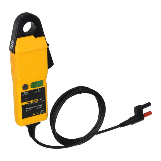
Page 7: Operating Instructions
Jaws Battery Cover Screw (Captive) ehr04.eps Figure 1. i30s & i30 AC/DC Current Clamps W Warning To avoid injury, when using the probe ensure that your fingers are behind the protective barrier as shown in Figure 1. Do not use the probe if any part... -
Page 8: Battery Replacement
Current Measurement Switch on the probe using the On – Off switch and check that the LED is lit. Connect the output lead to an oscilloscope, multimeter, or other measuring equipment. If necessary adjust the probe output voltage to zero as described in section Zero Adjustment. -
Page 9: Limited Warranty And Limitation Of Liability
LIMITED WARRANTY AND LIMITATION OF LIABILITY This Fluke product will be free from defects in material and workmanship for one year from the date of purchase. This warranty does not cover fuses, disposable batteries, or damage from accident, neglect, misuse, alteration, contamination, or abnormal conditions of operation or handling.
Need help?
Do you have a question about the i30s and is the answer not in the manual?
Questions and answers