Table of Contents
Advertisement
Quick Links
Advertisement
Table of Contents

Related Manuals for DALBO MINIMAX 830 2008


Summary of Contents for DALBO MINIMAX 830 2008
- Page 1 MINIMAX 830 2008 830 cm Serial no.: 100-xxx...
- Page 3 Congratulations on the purchase of your new roller. For safety reasons and to achieve opti- mum service from the product, please read the User Guide before use. © Copyright 2002. All rights reserved, DALBO A/S This product has: Type no.: Serial no.:...
-
Page 5: Table Of Contents
Table of Contents SAFETY ............................7 ............................7 ENERAL ............................8 YDRAULICS ............................8 OUNTING ........................8 AINTENANCE AND REPAIR ..........................9 OAD TRANSPORT ............................9 ORRECT USE TECHNICAL DATA ......................... 10 HOW TO USE THIS MANUAL ......................11 ............................11 ELIVERY USES ............................ - Page 6 HYDRAULIC DIAGRAM........................28 SPARE PARTS ..........................29...
-
Page 7: Safety
Safety This symbol appears in the instruction manual each time there is a safety warning concerning your safety, the safety of others or functionality of the machine. All safety instructions must be observed and made available to all users of the ma- chine. -
Page 8: Hydraulics
Hydraulics • Lower machine fully for any repair work on the hydraulic system. Relieve hy- draulic pressure, switch engine off and remove ignition key. • Clean hydraulic connections thoroughly before reconnecting. When connecting hydraulic hoses to tractor hydraulics, ensure they are not under pressure. •... -
Page 9: Road Transport
Road transport • All safety and warning precautions mandatory by law must be fitted and tested before transporting the machine on public roads. The driver is responsible for correct lighting and warning signs in accordance with traffic regulations. • Check with local traffic authorities whether transport on public roads is allowed given the machine's dimensions. -
Page 10: Technical Data
Technical data MINIMAX 2008 Size (cm) HP (recommended) 140 – 200 Gross weight kg: 4100 Sections (pcs.) Axles (pcs.) Wheels 10.0/75-15.3... -
Page 11: How To Use This Manual
How to use this manual The sequence of subject matter in this manual can seem illogical. Please refer to the table of contents for page numbers for individual items. The manual is divided into 5 main sections: • Safety • Starting routine and running •... -
Page 12: Uses
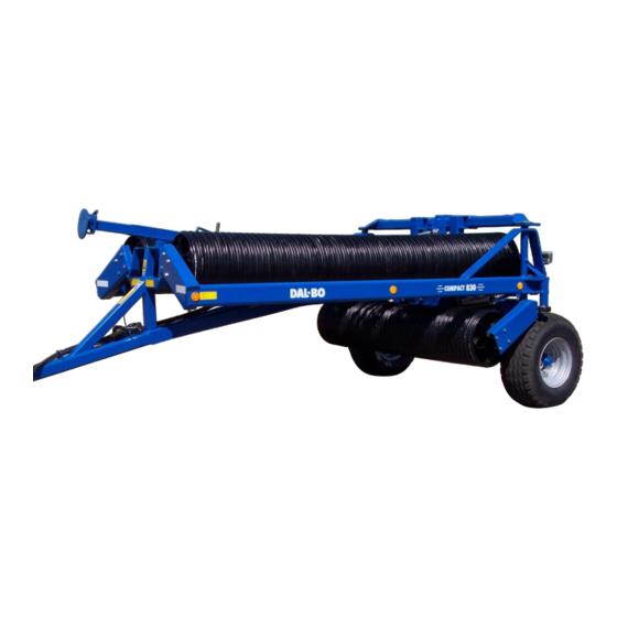
Uses This is a standard roller, designed for rolling and levelling ploughed and sown are- Fig. 1 The roller has three articulated sections and integrated mechan- ical weight equalisation, in which the sections can move inde- pendently of each other. MINIMAX 2008 830... -
Page 13: Connecting And Disconnecting
Connecting and disconnecting Connecting Fig. 2 Connect roller to the tractor's fixed towbar, where drawbar (A) must fit between the towbar forks. Insert pin, retract support leg and place in working position (B) • Remember to secure towbar pin with split pin or the like. •... -
Page 14: Disconnection
Disconnection The roller must be folded up (transport position) or extended before disconnection. Lower support leg to lift roller drawbar from tractor towbar. Remove pin and dis- connect hydraulic hoses. Remember to depressurise hoses before disconnecting them. -
Page 15: Setting Up
Setting up The roller is supplied with factory settings, but fine adjustment will always be re- quired before use. Numerous adjustment options make the roller more flexible and ensure maximum use. To achieve uniform pressure applied on the ground, the drawbar must be correctly set up for the tractor used. -
Page 16: Operation
Operation Correct operation is vital for optimum use of the roller. This applies to working in the field and for safety. Always ensure you are fully familiar with all safety aspects of the machine. Extending and folding up Extending and folding the machine up must always be performed with tractor parked. -
Page 17: Fold Up
Fold up Fig. 7 1. Activate extend cylinder (marked: Red) to lift end of side sections (A) as much as possible. Fig. 8 2. Activate raise/lower cylinder (marked: White) to full length. Roller will lift from ground Fig. 9 3. Activate extend cylinder to fold side sections in. -
Page 18: Maintenance
Maintenance Good maintenance ensures long service life and optimum use. Grease nipples are fitted where wear is heaviest. Tighten all screw connections after first working day. Check all split pins and bolts to avoid mechanical failure. Check hydraulic system for leaks. Lubrication Fig. -
Page 19: Adjustment
Adjustment Wheels Lubricate and adjust wheel bearings at least once annually. Check tyre pressures at least once annually (see recommended pressure on tyre). Adjustment and lubrication of wheel bearings 1. Remove hub caps. 2. Remove split pin. 3. Tighten castle nut 1/6th of a turn until hole is aligned with axle. Turn wheel, check for resistance. -
Page 20: Replacement Andrepairs
Replacement and repairs Safety is vital for all repair work on the roller. Always observe the following points, plus those under Safety First in the instruction manual. When replacing cylinders, always fill new cylinder with oil before pressurising sys- tem. - Page 21 Activate extend cylinder after fitting until cylinder shows movement. Reverse cyl- inder until it returns to start position. Move cylinder backwards and forward sever- al times. Raise roller fully onto wheels, extend side sections fully to bleed system. Ensure no personnel are within the extension radius of the side sections. Replacing gaskets REMOVAL: 1.
-
Page 22: Replacing Raise/Lower Cylinder
Ensure that thread is absolutely clean and free of oil or other impurities before applying Loctite. Do not fill with oil for 12 hours after use of Loctite. 5. Lubricate collar pos. 9 on collar shoe, and cylinder tube end inside using lubricating oil. -
Page 23: Replacing Gaskets On Raise/Lower Cylinder
Replacing gaskets on raise/lower cylinder Fig. 19 1. Drain oil from cylinder by moving ram carefully backwards and forwards. 2. Extend ram to centre position. Unscrew upper part (pos. 3) from cylinder tube (pos. 1). Use special tool to remove upper part. If upper part is stuck, heat front of sleeve. -
Page 24: Removal/Fitting Wheel
Removal/fitting wheel Before removing wheel, fully extend roller with rings resting on ground. Wheels will then be raised free of ground. Remove wheel nuts. Remove wheel. Replace wheel, hand-tighten wheel nuts. Lower wheels to ground. Tighten wheel nuts to 300 Nm. Ensure wheel nuts and wheel surfaces are clean to avoid nuts loosening. -
Page 25: Replacing Rollers
Fitting 1. Fit bearing outer rings pos. 17+18 in hub housing pos. 22 2. Fit seal ring pos. 16 3. Fit bearing inner ring pos. 18 on axle pos. 2 and fit axle in hub housing 4. Fit bearing inner ring pos. 17 on axle pos. 2 5. -
Page 26: Replacing Middle Roller
Replacing middle roller Fig. 24 1. Slacken bolts (A) 2. Activate raise/lower cylinder and lower roller until wheels and rollers are resting on ground and bolts are loose. 3. Remove bolts 4. Raise roller onto wheels. 5. Rings can be rolled off roller. 6. -
Page 27: Scrapping
Scrapping Fully extend roller. It is essential that all cylinders are removed. Beware of the weight of any given part when removing or disassembling. All parts must be supported or lifted to avoid danger of falling. Disconnect hydraulic hoses and cylinders and drain oil. Collect oil in container to avoid pollution. - Page 28 Hydraulic diagram Fig. 25...
- Page 29 Spare parts...
Need help?
Do you have a question about the MINIMAX 830 2008 and is the answer not in the manual?
Questions and answers