Inovance SV660N Series Hardware Manual
Hide thumbs
Also See for SV660N Series:
- Advanced user's manual (426 pages) ,
- Startup procedure (80 pages)
Table of Contents
Advertisement
Quick Links
Advertisement
Table of Contents

Related Manuals for Inovance SV660N Series


Summary of Contents for Inovance SV660N Series
-
Page 2: Preface
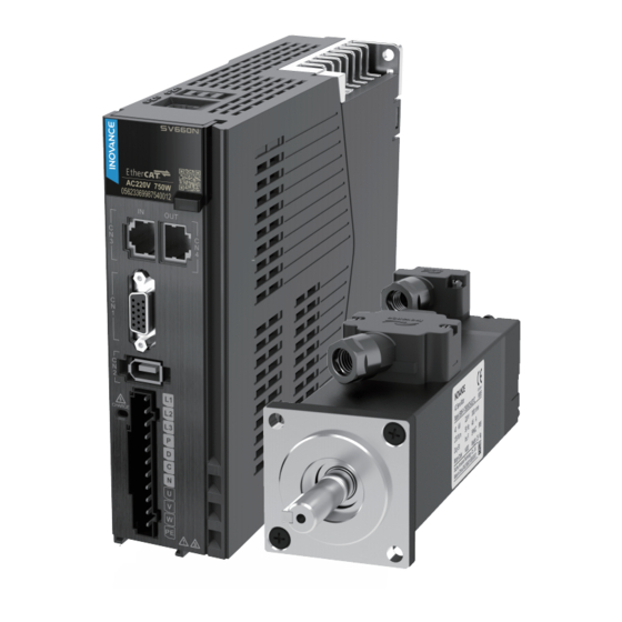
Preface Introduction The SV660N series high performance AC servo drive provides a power range from 0.05 kW to 7.5 kW. It supports EtherCAT communication protocol and carries Ethernet communication interfaces to work with the host controller for a networked operation of multiple servo drives. - Page 3 Preface Description Name Data code Introduces faults and fault levels, the SV660N Series Servo Drive 19011847 troubleshooting process, warning codes and Troubleshooting Guide fault codes. Presents the safety function and related SV660N Series Servo Drive certifications and standards, wiring, 19011846...
- Page 4 ● download manuals. Warranty agreement Inovance provides warranty service within the warranty period (as specified in your order) for faults or damage that occur during normal operation. Maintenance will be charged after the warranty period expires. Within the warranty period,maintenance will be charged for the following damage: Damage caused by operations not following the instructions in the user guide ●...
- Page 5 Damage or secondary damage caused by force majeure (natural disaster, ● earthquake, and lightning strike) The maintenance fee is charged according to the latest Price List of Inovance. If otherwise agreed upon, the terms and conditions in the agreement shall prevail. For details, see Product Warranty Card.
-
Page 6: Table Of Contents
Table of Contents T T a a b b l l e e o o f f C C o o n n t t e e n n t t s s Preface ................1 Fundamental Safety Instructions . - Page 7 Table of Contents 3.5.4 Encoder Cable Specifications ..........79 3.6 Communication Terminals (CN3 and CN4) .
-
Page 8: Fundamental Safety Instructions
Use this equipment according to the designated environment requirements. ● Damage caused by improper use is not covered by warranty. Inovance shall take no responsibility for any personal injury or property damage ● caused by improper usage. Safety Levels and Definitions Indicates that failure to comply with the notice can result in death or severe personal injury. - Page 9 Fundamental Safety Instructions Check whether the packing is intact and whether there is damage, water seepage, ● dampness, and deformation before unpacking. Unpack the package by following the unpacking sequence. Do not strike the package ● violently. Check whether there is damage, rust, or injury on the surface of the equipment and ●...
- Page 10 Fundamental Safety Instructions Read through the guide and safety instructions before installation. ● Do not install this equipment in places with strong electric or magnetic fields. ● Before installation, check that the mechanical strength of the installation site can bear ●...
- Page 11 Fundamental Safety Instructions Do not connect the input power supply to the output end of the equipment. Failure to ● comply can result in equipment damage or even a fire. When connecting a drive to the motor, check that the phase sequences of the drive and ●...
- Page 12 Fundamental Safety Instructions The equipment must be operated only by professionals. Failure to comply will result in ● death or personal injury. Do not touch any connecting terminals or disassemble any unit or component of the ● equipment during operation. Failure to comply will result in an electric shock. Do not touch the equipment casing, fan, or resistor with bare hands to feel the ●...
- Page 13 Fundamental Safety Instructions Submit the repair request according to the warranty agreement. ● When the fuse is blown or the circuit breaker or earth leakage current breaker (ELCB) ● trips, wait for at least the time designated on the equipment warning label before power‑on or further operations.
- Page 14 Fundamental Safety Instructions Safety label Description Never fail to connect the protective earth (PE) terminal. Read ● through the guide and follow the safety instructions before use. Do not touch terminals within 15 minutes after disconnecting the ● power supply to prevent the risk of electric shock. Do not touch the heatsink with power ON to prevent the risk of burn.
-
Page 15: Installation
" Figure 1–1 " on page 15 Check whether the product delivered is in good condition. If Check whether the there is any missing or damage, contact Inovance or your product is intact. supplier immediately. ‑... - Page 16 Installation Table 1–1 Dimensions of the outer packing box Outer width Outer height Outer depth Weight Servo drive model Size (kg) (mm) (mm) (mm) SV660N****I S1R6, S2R8 250.0 90.0 0.96 S5R5 225.0 205.0 1.17 S7R6, T3R5, T5R4 235.0 105.0 215.0 1.48 S012, T8R4, T012 235.0...
-
Page 17: Installation Environment
Derating is required for altitudes above 1000 m (derate 1% for Altitude ● every additional 100 m). For altitudes above 2000 m, contact Inovance. ● Mounting/Operating temperature: 0℃ to 55℃ For temperatures ● between 0℃ to 45℃, derating is not required. For temperatures above 45℃, derate 2% for every additional 1℃. -
Page 18: Installation Clearance
Installation Requirement Item IP rating IP20. Pollution Degree 2 and below Install the servo drive in a place that meets the following requirements: Free from direct sunlight, dust, corrosive gas, explosive and ● inflammable gas, oil mist, vapor, water drop, and salty element Insusceptible to vibration (away from equipment that may ●... - Page 19 Installation Figure 1‑3 Clearance for side‑by‑side installation Servo drives rated at 0.2 kW to 0.75 kW (size A and size B) support compact installation, in which a clearance of at least 1 mm (0.04 in.) must be reserved between every two servo drives. When adopting compact installation, derate the load rate to 75%.
- Page 20 Installation Figure 1‑4 Clearance for compact installation Servo drives in sizes C and D (rated power: 1.0 kW to 3 kW) support zero‑clearance installation between every two servo drives, without the need for derating. ‑19‑...
-
Page 21: Installation Dimensions
Installation Figure 1‑5 Zero‑clearance installation 1.1.4 Installation Dimensions Drives in Size A (Rated Power: (0.2 kW to 0.4 kW): SV660NS1R6I, SV660NS2R8I Figure 1‑6 Dimension drawing of servo drives in size A ‑ ‑... - Page 22 Installation Servo drives in size B (rated power: 0.75 kW): SV660NS5R5I Figure 1‑7 Dimension drawing of servo drives in size B Drives in Size C (Rated Power: (1.0 kW to 1.5 kW): SV660NS7R6I, SV660NT3R5I, SV660NT5R4I Figure 1‑8 Dimension drawing of servo drives in size C Drives in Size D (Rated Power: (1.5 kW to 3.0 kW): SV660NS012I, SV660NT8R4I, SV660NT012I Figure 1‑9 Dimension drawing of servo drives in size D...
-
Page 23: Installation Precautions
Installation Drives in Size E (Rated Power: (5.0 kW to 7.5 kW): SV660NT017I, SV660NT021I, SV660NT026I Figure 1‑10 Dimension drawing of servo drives in size E 1.1.5 Installation Precautions Table 1–3 Installation Precautions Description Item Install the servo drive vertically and upward to facilitate heat ●... - Page 24 Installation Description Item As shown in the figure below, route the servo drive cables downwards to prevent liquid from flowing into the servo drive along the cables. Wiring requirements Insert the dust‑proof cover into the communication port (CN5/ CN6) not in use. This is to prevent unwanted objects, such as solids or liquids, from falling into the servo drive and resulting in faults.
-
Page 25: Installation Guide
Installation 1.1.6 Installation Guide The servo drive supports backplate mounting only. Figure 1‑11 Backplate mounting Note Servo drives in sizes A and C are secured by two screws, with one screw on the top ● and the other one at the bottom. Servo drives in size D are secured by three screws, with two screws on the top and ●... -
Page 26: Installing The Options
Installation Installing the Options 1.2.1 Instructions for Installing the Fuse and Circuit Breaker To prevent electric shock, when the fuse is blown or the circuit breaker trips, wait for at least the time designated on the warning label before powering on the drive or operating peripheral devices. -
Page 27: Instructions For Installing The Emc Filter
Installation 1.2.3 Instructions for Installing the EMC Filter Figure 1‑13 Installing the AC input reactor 1.2.4 Installation of the Magnetic Ring and Ferrite Clamp Figure 1‑14 Installation of the magnetic ring ‑ ‑... -
Page 28: 屏蔽支架的安装说明
Installation Figure 1‑15 Installation of the ferrite clamp 1.2.5 屏蔽支架的安装说明 EMC支架以及与其匹配的喉箍配和伺服线缆使用,以减轻电磁干扰。 Figure 1‑16 屏蔽支架安装示意图 ①:用2颗M4螺钉将屏蔽支架固定到驱动器上,建议锁紧扭矩1.2Nm。 ● ②:将卡箍套在电缆屏蔽层和屏蔽支架上,拧紧螺钉使用电缆屏蔽层固定在屏蔽支架 ● 上;依据接线图纸,完成电机动力线及抱闸电缆的接线。 ‑27‑... -
Page 29: System Wiring Diagram
System Wiring Diagram System Wiring Diagram System Wiring Diagram Figure 2‑1 Wiring example of a single‑phase 220 V system ‑ ‑... - Page 30 System Wiring Diagram Figure 2‑2 Wiring example of a three‑phase 380 V system ‑29‑...
- Page 31 System Wiring Diagram Figure 2‑3 Wiring example of a three‑phase 380 V system Note When an external braking resistor is needed, connect it between terminals P and C ● (remove the jumper bar between terminals P and D). If an external braking resistor is not needed, short terminals P and D.
-
Page 32: System Structure
System Wiring Diagram System Structure The servo drive is directly connected to an industrial power supply, with no ● isolation such as a transformer. A fuse or circuit breaker therefore must be connected to the input power supply to prevent electric shock in the servo system. For the sake of safety, install a residual current device (RCD) to provide protections against overload and short circuit or a specialized RCD to protect the grounding cable. -
Page 33: Introduction To Wiring Terminals
Introduction to Wiring Terminals Introduction to Wiring Terminals Wiring Precautions Read through the safety instructions in Chapter "Fundamental Safety Instructions". Failure to comply may result in serious consequences. Do not use the power from IT system for the servo drive. Use the power from TN/ ●... - Page 34 Introduction to Wiring Terminals The specification and installation of external cables must comply with applicable ● local regulations. Observe the following requirements when the servo drive is used on a vertical axis. ● Set the safety device properly to prevent the workpiece from falling upon —...
-
Page 35: Terminal Pin Layout Of The Servo Drive
Introduction to Wiring Terminals Locations with interference caused by static electricity — — Locations with strong electric field or magnetic field — — Locations with radioactive rays — — Terminal Pin Layout of the Servo Drive Servo drives in size A (rated power: 0.2 kW to 0.4 kW): SV660NS1R6I and SV660NS2R8I Figure 3‑1 Terminal pin layout of servo drives in size A ‑... - Page 36 Introduction to Wiring Terminals Size B (rated power: 0.75 kW): SV660NS5R5I Figure 3‑2 Terminal pin layout of servo drives in size B ‑35‑...
- Page 37 Introduction to Wiring Terminals Sizes C and D (rated power: 1.0 kW to 3.0 kW): size C: SV660NS7R6I/D: SV660NS012I Figure 3‑3 Terminal pin layout of servo drives in size C and size D (220V) ‑ ‑...
- Page 38 Introduction to Wiring Terminals Sizes C and D (rated power: 1.0 kW to 3.0 kW): size C: SV660NT3R5I and SV660NT5R4I; size D: SV660NT8R4I, SV660NT012I Figure 3‑4 Terminal pin layout of servo drives in size C and size D (380V) ‑37‑...
-
Page 39: Introduction To Main Circuit Terminals
Introduction to Wiring Terminals Size E (rated power: 5.0 kW to 7.5 kW): SV660NT017I, SV660NT021I, and SV660NT026I Figure 3‑5 Terminal pin layout of servo drives in size E Note CN6 (STO terminal) is only applicable to customized model ‑FS. Introduction to Main Circuit Terminals 3.3.1 Wiring Precautions Do not connect the input power supply cables to the output terminals U, V, and W. - Page 40 ● on or off frequently within 1s, E740/E136/E430 may occur (see section Description of Error Codes in SV660N Series Servo Drive Troubleshooting Guide). In this case, power on the servo drive again after waiting for the specified ON/OFF interval. If...
-
Page 41: Main Circuit Wiring Requirements
Introduction to Wiring Terminals frequent ON/OFF operation is needed, the time interval between ON and OFF must be at least 1 min. The servo drive carries a capacitor in the power supply part, and this capacitor will be charged with a high current for 0.2s upon power‑on. Turning on/off the power supply frequently affects the performance of main circuit components inside the servo drive. -
Page 42: Recommended Cable Specifications And Models
Introduction to Wiring Terminals To protect the main circuit, separate and cover the surface that may come into ● contact with the main circuit. Prevent foreign objects from entering the wiring area of the terminal block. ● Do not solder the twisted conductors. ●... - Page 43 Introduction to Wiring Terminals Table 3–3 Recommended main circuit cables P⊕, D, C, NΘ, Drive model Grounding L1C, L2C L1, L2, L3/R, S, T U, V, W, PE N2, N1 SV660N****I terminal Rated input (AWG) (AWG) Size Model rent Single‑phase 220 V S1R6 2x0.52 3x0.52...
- Page 44 Introduction to Wiring Terminals Table 3–5 Main circuit cable lug and tightening torque Recommended PVC cable model (at 40℃) Servo drive model SV660N****I Rated input Tightening U, V, W, PE Grounding current Brake cable lug torque Size Model cable lug cable lug (N·m) Single‑phase 220 V...
- Page 45 Introduction to Wiring Terminals Servo drive model SV660N****I Terminal block T017 Size E T021 ‑ T026 Table 3–8 Specifications of motor output cables MS1H1/H4 05B–10C (0.05 kW to 1 kW) Oil‑resistant shielded flexible Cable type Regular cable Flexible cable cable S6‑L‑M/B***‑X.X S6‑L‑M/B***‑X.X‑T S6‑L‑M/B***‑X.X‑TS...
- Page 46 Introduction to Wiring Terminals MS1H2 10C–50C (1 kW to 5 kW)/MS1H3 85B–18C (0.85 kW to 1.8 kW) Internal structure and conductor colors Fill in "X.X" of the model number with cable length. Table 3–10 Specifications of motor output cables MS1H3 29C–75C (2.9 kW to 7.5 kW) Oil‑resistant shielded flexible Cable type Regular cable...
- Page 47 70°C (Contact the manufacturer if the ambient temperature exceeds 40°C.) Requirements for UL cable selection are described in " Cable requirements " on page Note If the recommended cable specifications for peripheral devices or optional parts exceed the applicable cable specification range, contact Inovance. ‑ ‑...
-
Page 48: Main Circuit Terminal Layout
See the nameplate for the rated voltage class. terminals) P⊕, N⊖ Used by the common DC bus for multiple servo drives. (DC bus terminals) Contact Inovance for technical support. P⊕, C Terminals for If an external braking resistor is needed, connect it connecting external between terminals P⊕... - Page 49 L1 and L2. P⊕, N⊖ Used by the common DC bus for multiple servo drives. (DC bus terminals) Contact Inovance for technical support. Remove the jumper bar between terminals P⊕ and C before connecting an external braking resistor P⊕, D, C between terminals P⊕...
- Page 50 L1 and L2. P⊕, N⊖ Used by the common DC bus for multiple servo drives. (DC bus terminals) Contact Inovance for technical support. Remove the jumper bar between terminals P⊕ and C before connecting an external braking resistor P⊕, D, C between terminals P⊕...
- Page 51 P⊕, N⊖ Used by the common DC bus for multiple servo drives. (DC bus terminals) Contact Inovance for technical support. Remove the jumper bar between terminals P⊕ and C before connecting an external braking resistor P⊕, D, C between terminals P⊕...
- Page 52 Introduction to Wiring Terminals Size E (rated power: 5.0 kW to 7.5 kW): SV660NT017I, SV660NT021I, and SV660NT026I Figure 3‑12 Pin assignment of main circuit terminal of servo drives in size E Table 3–15 Description of main circuit terminal pins of servo drives in size E Name Description L1C, L2C...
-
Page 53: Connecting The Motor (Uvw)
Introduction to Wiring Terminals 3.3.5 Connecting the Motor (UVW) Keep the lead wire of the motor cable shield as short as possible, with its width (b in the following figure) not shorter than 1/5 of its length (a in the following figure). Figure 3‑13 Lead‑out of the motor cable shield The following figure shows the wiring diagram for a terminal‑type motor. - Page 54 [1] The flange size refers to the width of the mounting flange. ● Power cable colors are subject to the actual product. All cable colors mentioned in ● this guide refer to Inovance cable colors. The connection diagram for a flying leads type motor is shown in the following ● figure.
- Page 55 ● Power cable colors are subject to the actual product. All cable colors mentioned in ● this guide refer to Inovance cable colors. The following table describes the connector for high‑power motor power cables. ● Table 3–18 Description of the power cable connector (motor side)
-
Page 56: Wiring Of External Emc Filter
Power cable colors are subject to the actual product. All cable colors mentioned in ● this guide refer to Inovance cable colors. 3.3.6 Wiring of External EMC Filter Install the filter near the input terminals of the drive. The cable between the filter and the drive must be shorter than 30 cm. -
Page 57: Wiring Of The Power Supply
Introduction to Wiring Terminals Figure 3‑16 Installing the filter 3.3.7 Wiring of the Power Supply Single‑phase 220 V models: SV660NS1R6I, SV660NS2R8I, SV660NS5R5I, ● SV660NS7R6I and SV660NS012I ‑ ‑... - Page 58 Introduction to Wiring Terminals Figure 3‑17 Main circuit wiring Note 1KM: Electromagnetic contactor; 1Ry: Relay; 1D: Flywheel diode ● DO is set as alarm output (ALM+/‑). When the servo drive alarms, the power supply ● will be cut off automatically. SV660NS1R6I and SV660NS2R8I are not configured with built‑in regenerative resistors, if the regenerative resistor is needed, connect an external regenerative resistor between P⊕...
- Page 59 Introduction to Wiring Terminals Figure 3‑18 Main circuit wiring of three‑phase 220 V models Note 1KM: Electromagnetic contactor; 1Ry: Relay; 1D: Flywheel diode ● The DO is set as alarm output (ALM+/‑). When the servo drive alarms, the power ● supply is cut off automatically and the alarm indicator lights up.
-
Page 60: Grounding And Wiring
Introduction to Wiring Terminals Figure 3‑19 Main circuit wiring of three‑phase 380 V models Note 1KM: Electromagnetic contactor; 1Ry: Relay; 1D: Flywheel diode ● The DO is set as alarm output (ALM+/‑). When the servo drive alarms, the power ● supply is cut off automatically and the alarm indicator lights up. - Page 61 Introduction to Wiring Terminals To prevent electric shocks, ground the grounding terminal properly. Observe ● related national or regional regulations during grounding. To prevent electric shocks, ensure the protective grounding conductor complies ● with technical specifications and local safety standards. Keep the length of the grounding cable as short as possible.
- Page 62 Introduction to Wiring Terminals It is recommended to install the drive to a conductive metal surface. Ensure the ● whole conductive bottom of the drive is connected properly to the mounting face. Tighten the grounding screw with specified tightening torque to prevent the ●...
- Page 63 Introduction to Wiring Terminals Multi-drive grounding Side‑by‑side installation of multiple drives: Table 3–21 Description for grounding of multiple drives installed side by side Description Connect the motor output cable shield to the output PE terminal of the ① servo drive. Connect the main circuit input PE terminal of the servo drive to the grounding copper busbar of the control cabinet through a protective ②...
-
Page 64: Control Terminal (Cn1)
Introduction to Wiring Terminals Table 3–22 Wiring requirements Wiring requirements Place the control unit and the drive unit in two separate control cabinets. If multiple control cabinets are used, connect the control cabinets by using a PE cable with a cross‑sectional area of at least 16 mm equipotentiality between the control cabinets. - Page 65 Introduction to Wiring Terminals I/O signal cable selection It is recommended to use shielded signal cables to prevent I/O signal circuit from being disturbed by external noise. Use separate shielded cables for different analog signals. It is recommended to use shielded twisted pairs for digital signals. Figure 3‑21 Diagram of shielded twisted pairs Control Cable Specifications Table 3–23 Recommended Control Cable Specifications...
-
Page 66: Terminal Layout
Introduction to Wiring Terminals 3.4.1 Terminal Layout +24V DO3+ COM- DO3- COM+ DO2+ DO2- DO1+ DO1 - Figure 3‑22 Control terminal pin layout of servo drives in sizes A and B ‑65‑... - Page 67 Introduction to Wiring Terminals Figure 3‑23 Control terminal pin layout of servo drives in sizes C, D and E Note Use shielded cables as signal cables, with both ends of the shielded cable grounded. Table 3–24 Description of DI/DO signals Signal Default Pin No.
-
Page 68: Di/Do Signals
Introduction to Wiring Terminals Note DI logic level: "0" < 3 V; "1" > 20 V. 3.4.2 DI/DO Signals DI circuit The circuits for DI1 to DI5 are the same. The following takes the DI1 circuit as an example. The host controller provides relay output: ●... - Page 69 Introduction to Wiring Terminals The host controller provides open‑collector output. ● When you use the internal 24 V power supply: ■ When you use an external power supply: ■ Note PNP and NPN input cannot be applied in the same circuit. DO circuit The circuits for DO1 to DO3 are the same.
- Page 70 Introduction to Wiring Terminals Note When the host controller provides relay input, a flywheeling diode must be installed. Other‑ wise, the DO may be damaged. The host controller provides optocoupler input. ● ‑69‑...
-
Page 71: Wiring Of The Brake
Introduction to Wiring Terminals Note The maximum permissible voltage and current capacity of the optocoupler output circuit inside the servo drive are as follows: Max. voltage: 30 VDC ● Max. current: DC 50 mA ● 3.4.3 Wiring of the Brake The brake is used to prevent the motor shaft from moving and lock the position of the motor and the motion part when the drive is in the non‑operational status. - Page 72 When determining the length of the motor brake cable, take the voltage drop caused by cable resistance into account. The input voltage must be at least 21.6 V to enable the brake to work properly. The following table lists brake specifications of Inovance MS1 series servo motors.
-
Page 73: Encoder Terminal (Cn2)
Introduction to Wiring Terminals Table 3–25 Brake specifications Supply Holding Exciting Coil resistance Release time Apply time Backlash voltage torque current Motor model (Ω) (±7%) (ms) (ms) (°) (VDC) (N·m) ±10% MS1H1‑05B/10B 0.32 94.4 0.25 ≤ 20 ≤ 40 ≤ 1.5 MS1H4‑10B MS1H1‑20B/40B 75.79... -
Page 74: Connecting The Absolute Encoder
Introduction to Wiring Terminals Table 3–26 Description of encoder terminal pins Description Name 5 V power supply +5 V ‑ Reserved ‑ Reserved ‑ Encoder signal PS‑ Enclosure Shield 3.5.2 Connecting the Absolute Encoder Figure 3‑27 Terminal‑type signal cable wiring ‑73‑... - Page 75 The encoder cable color is subject to the color of the actual product. Cable colors ● mentioned in this guide all refer to Inovance cables. Lead wires of the battery box: Figure 3‑29 Description of the lead wire color of the battery box ‑...
- Page 76 Introduction to Wiring Terminals Keep the battery in environments within the required ambient temperature range ● and ensure the battery is in reliable contact and carries sufficient power capacity. Otherwise, encoder data loss may occur. Model of the battery box (battery included): S6‑C4A ●...
- Page 77 Introduction to Wiring Terminals Table 3–28 Flying leads type motor encoder cable connector (9‑pin) Applica Terminal Pin Layout ble Motor Outline Drawing of the Connector Signal Flange Type Pin No. Color Name Size +5 V Twisted pair Orange Blue Twisted pair Purple PS‑...
-
Page 78: Installing Absolute Encoder Battery Box
Introduction to Wiring Terminals Table 3–29 Absolute encoder cable connector (MIL‑DTL‑5015 series 3108E20‑29S aviation connector) Applica Terminal Pin Layout ble Motor Outline Drawing of the Connector Signal Type Flange Pin No. Color Name Size +5 V Twisted pair Orange Blue Twisted pair Purple... - Page 79 Introduction to Wiring Terminals Installing the battery box Figure 3‑30 Installing the battery box (bottom view) Removing the battery box The battery may generate leakage liquid after long‑term use. Replace it every two years. Remove the battery box in steps shown in the preceding figure, but in the reverse order.
-
Page 80: Encoder Cable Specifications
Introduction to Wiring Terminals Improper use of the battery may result in liquid leakage which corrodes the components or leads to battery explosion. Observe the following precautions during use: Insert the battery with polarity (+/‑) placed correctly. ● Leaving an idled or retired battery inside the device may lead to electrolyte ●... -
Page 81: Communication Terminals (Cn3 And Cn4)
13.5 105.0 11.4±0.3 Note If the cables of above 16AWG are required, contact the sales personnel of Inovance. Communication Terminals (CN3 and CN4) Terminal layout Figure 3‑31 Communication terminal pin layout (sizes A and B) Table 3–31 EtherCAT communication terminal pin assignment (sizes A and B) Description Pin No. - Page 82 Introduction to Wiring Terminals Description Pin No. Name ‑ ‑ 15 and 16 Transmitting data (+) Transmitting data (‑) TD‑ Receiving data (+) 4 and 5 ‑ ‑ Receiving data (‑) RD‑ ‑ ‑ 7 and 8 Figure 3‑32 Communication terminal pin layout (sizes C, D and E) Table 3–32 EtherCAT communication terminal pin assignment (sizes C, D and E) Description Name...
- Page 83 Introduction to Wiring Terminals Figure 3‑33 Wiring of communication cables Terminal connection Topology ● The communication topology of EtherCAT is flexible without any limit. The SV660N series servo drive carries IN and OUT ports. ‑ ‑...
- Page 84 Introduction to Wiring Terminals Figure 3‑34 Communication network topology Linear topology ● Communication cable selection The EtherCAT communication cable must be Ethernet Category 5 (100BASE‑TX) network cable or high‑strength shielded network cable. The cables used for the servo ‑83‑...
- Page 85 Note Cable selection is subject to the instructions provided by the cable supplier. See "Instruc‑ tions for purchasing servo encoder cables/power cables" in Inovance business system. Table 3–34 Information for ordering the communication cable Length (m)
- Page 86 Introduction to Wiring Terminals Cables are ordered from suppliers including Haituo (the cable price is added by RMB 5 for every additional 1 m based on the price of S6‑L‑T04‑10.0. The cable price is also related to the magnitude of the order). The order quantity will also affect the pricing. Figure 3‑35 Network port connector Note The head of the dual‑port network terminal cannot be too thick, otherwise, interference...
-
Page 87: Communication Terminal (Cn5)
Introduction to Wiring Terminals Communication Terminal (CN5) Terminal layout Figure 3‑36 Layout of terminals Table 3–36 Pin assignment Pin No. Definition 1–5 ‑ RS232‑TXD RS232‑RXD Description You can connect the servo drive to PC with a PC communication cable through the CN5 terminal. -
Page 88: Sto Safety Terminal (Cn6)
Introduction to Wiring Terminals Table 3–38 Pin assignment of DB9 terminal on the PC side Assignment Description Pin layout Pin No. PC receiving end PC‑RXD PC transmitting PC‑TXD Ground Enclosure Shield If the host controller supports USB interface only, use the serial‑to‑USB cable. Figure 3‑38 Serial‑to‑USB conversion Recommendations: Manufacture: Z‑TEK Model: ZE551A, equipped with a 0.8 m USB extension cable Chip model: FT232... - Page 89 Introduction to Wiring Terminals Terminal layout Table 3–39 Pin assignment of STO safety terminal Assignment Description Pin No. COM‑ STO reference GND Internal 24 V power supply Control input of STO1 STO1 Control input of STO2 STO2 Two isolated inputs are configured to dual‑channel inputs of the STO function: STO1/ STO2.
- Page 90 Introduction to Wiring Terminals Item Description Characteristics Voltage range 24 VDC (±15%) ‑ This is the value per Input current 3.6 mA (Typ.) channel. Standards of logic levels "0" < 5 V, "1" > 15 V ‑ Digital input impedance ‑...
- Page 91 Introduction to Wiring Terminals The maximum allowable cable length between the drive and the safety switch ■ is 30 m. Other requirements ● All wiring must be well protected, routed and clamped where practicable. ■ It must be assured that there is no pulling or pinching on the cable when ■...
-
Page 92: Wiring And Setting Of The Regenerative Resistor
Introduction to Wiring Terminals Wiring and Setting of the Regenerative Resistor Connecting the regenerative resistor Figure 3‑39 Wiring of external regenerative resistor For cables used for terminals P⊕ and C, see " 3.3.3 Recommended Cable Specifications and Models " on page 41 Observe the following precautions when connecting the external regenerative resistor: Remove the jumper between terminals P⊕... -
Page 93: Maintenance
Maintenance Maintenance Routine Inspection Standard operating conditions: Average annual ambient temperature: 30℃ Average load rate: < 80% Daily operating time: < 20 h 4.1.1 Routine Checklist Check the following items during routine inspection. Table 4–1 Routine checklist Routine Checklist Checked The ambient temperature and humidity are normal. -
Page 94: Regular Maintenance
To keep the servo drive and servo motor in good condition, perform parts replacement based on the replacement cycles listed in the following table. Contact Inovance or Inovance agent before replacement to double check whether the part needs to be replaced. -
Page 95: Replacing Components
Maintenance Standard Replacement Equipment Components Remarks Interval Bus filter capacitor About five years 2 to 3 years (10000 h to Cooling fan 30000 h) Aluminum electrolytic About five years capacitor on the PCB Servo drive 100,000 operations (depending on the Pre‑charge relay operating conditions) The standard... -
Page 96: Removing The Motor Oil Seal
Maintenance Specification of the key disassembly bolt Dimensions of the Flat Specifications of the Disassembly Motor Size Bolt (Inner Hexagon Bolt) Size 40 Type‑A flat No disassembly hole key—A3×3×14 Size 60 Type‑C flat M3 x 10 and above key—C5×5×16.5 Size 80 Type‑C flat M3 x 15 and above key—C6×6×25... - Page 97 Maintenance ‑ ‑...
-
Page 98: Certification And Standards Compliance
Certification and Standards Compliance Certification and Standards Compliance Table 5–1 Compliance list Directive Name Standard Certification 2014/30/EU EMC directive EN IEC 61800‑3 EN 61800‑5‑1 2014/35/EU CE certification LVD directive EN 60034 2011/65/EU RoHS directive EN 50581 UL61800‑5‑1 C22.2 No.274‑17 UL/cUL ‑... -
Page 99: Requirement For Compliance With Emc Directive
Certification and Standards Compliance 5.1.1 Requirement for Compliance with EMC Directive The SV660P series servo drive, which is applicable to the first environment and second environment, complies with EMC Directive 2014/30/EU and standard EN IEC 61800‑3. As required by EMC Directive 2014/30/EU and standard EN IEC 61800‑3, install an EMC filter on the input side of the drive and use shielded cables on the output side. -
Page 100: Requirements For Compliance With Lvd
Drives (IP20) intended to be installed inside the cabinet must be installed in a structure that prevents intrusion of unwanted objects from the top and the front. Main circuit wiring requirements For wiring requirements of the main circuit terminals, see SV660N Series Servo Drive Hardware Guide. Requirements of protective devices To comply with EN 61800‑5‑1, install a fuse/circuit breaker on the input side of the... -
Page 101: Ul&Cul Certification
Installation requirements Installation requirements for open‑type drives: SV660N series servo drives are open‑type drives that must be installed in a fireproof cabinet with the enclosure that provides effective electrical and mechanical protection. The installation must conform to local laws and regulations and related NEC requirements. - Page 102 PVC cable with continuous maximum allowable temperature of 75°C. The following conditions are used as premises: Ambient temperature: < 40°C ■ Normal operating ratings ■ If the recommended cables for peripheral equipment or options are not suitable for the product, contact Inovance. ‑101‑...
- Page 103 Certification and Standards Compliance Terminal cable selection To comply with UL61800‑5‑1 and CSA C22.2 No. 274‑17, power cables used for SV660 series servo drives must meet the following requirements: Compliant with NEC, Table 310‑16 of NFPA70. ● Comprised of copper conductors with a rated temperature not lower than 75°C ●...
- Page 104 Certification and Standards Compliance Drive model Recommend Bussmann SV660 series servo drive ed inverse Circuit breaker (A) conductor Rated input time lag fuse (A) Size Model current (A) breaker T8R4 ‑ Size D T012 ‑ T017 12.0 ‑ ‑ Size E T021 16.0 ‑...
-
Page 105: Solutions To Common Emc Problems
Solutions To Common EMC Problems Solutions To Common EMC Problems Malfunction of the Residual Current Device (RCD) If an RCD is needed, select the RCD according to the following requirements: The drive may generate DC leakage current in the protective conductor, a B‑type ●... -
Page 106: Harmonic Suppression
Solutions To Common EMC Problems Figure 6‑1 Magnetic ring on the input side Harmonic Suppression To suppress harmonics and improve the power factor to allow the drive to fulfill the standards, install an AC input reactor on the input side of the drive. For the reactor "... - Page 107 Solutions To Common EMC Problems Step Measure Use shielded cables as the I/O signal cables and connect the shield to the PE terminal. For details, see " Connecting Control Signals " on page 63 Reliably connect the PE terminal of the motor to the PE terminal of the servo drive, and connect the PE terminal of the servo drive to the PE terminal of the grid.
-
Page 108: Ethercat Communication Interference
Solutions To Common EMC Problems 6.3.2 EtherCAT Communication Interference Take the measures listed in the following table to suppress interference. Step The communication cable must be shielded Cat 5e. The communication port is tight and secure without the risk of poor contact. Separate communication cables from power cables with a distance of at least 30 Add an equipotential bonding grounding... - Page 109 *19011432C01*...
Need help?
Do you have a question about the SV660N Series and is the answer not in the manual?
Questions and answers