Fronius Smart Meter 63A-3 Operating Instructions Manual
Hide thumbs
Also See for Smart Meter 63A-3:
- Operating instructions manual (32 pages) ,
- Quick manual (20 pages) ,
- Quick start manual (10 pages)

Subscribe to Our Youtube Channel
Related Manuals for Fronius Smart Meter 63A-3


Summary of Contents for Fronius Smart Meter 63A-3
- Page 1 Operating Instructions Fronius Smart Meter 63A-3 EN-US Operating instructions 42,0426,0293,EA 013-15072024...
-
Page 3: Table Of Contents
Reading the Fronius Smart Meter operating parameters Commissioning Fronius SnapINverter General Connect to Fronius Datamanager 2.0 Configuring the Fronius Smart Meter as the primary meter Configuring the Fronius Smart Meter as a secondary meter Fronius GEN24 inverter General Installation using the web browser... -
Page 4: Safety Rules
Safety rules Explanation of DANGER! Safety Instruc- tions Indicates an immediate danger. ▶ Death or serious injury may result if appropriate precautions are not taken. WARNING! Indicates a possibly dangerous situation. ▶ Death or serious injury may result if appropriate precautions are not taken. CAUTION! Indicates a situation where damage or injury could occur. -
Page 5: Environmental Conditions
Any safety devices that are not functioning properly must be repaired by an au- thorized specialist before the device is switched on. Never bypass or disable protection devices. For the location of the safety and danger notices on the device, refer to the sec- tion headed “General”... -
Page 6: General
Together with the Fronius inverter, the Fronius Datamanager and the Fronius data inter- face, the Fronius Smart Meter provides a clear overview of your own power con- sumption. The meter measures the power flow to the loads or to the grid and forwards the information to the Fronius inverter via ModBus RTU/RS485 communication. - Page 7 Positioning at the feed-in point The positioning of the Fronius Smart Meter at the feed-in point. Positioning at the consumption point The positioning of the Fronius Smart Meter at the consumption point.
-
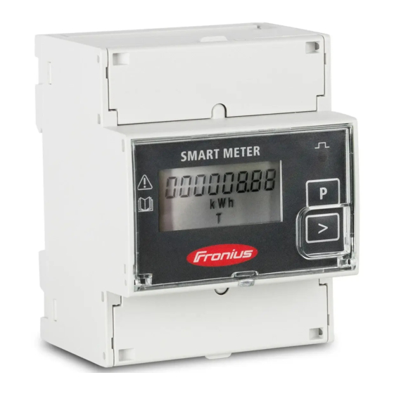
Page 8: Installation
21). Configure and commission the meter (see Installation The Fronius Smart Meter can be mounted on a 35 mm DIN rail. The housing comprises 4 DUs (division units, max. 72 mm). Protective cir- The Fronius Smart Meter is a hard-wired device and requires a disconnecting... -
Page 9: Cabling
Connect each voltage cable to the terminal strip as shown in the graphic below. Connecting the Fronius SnapINverter: data communic- Connect the data communication connections of the Fronius Smart Meter to the ation cable to Fronius system monitoring in the inverter. Several Smart Meters can be installed the inverter... - Page 10 Connect B to D-. ConnectC to -. Fronius GEN24 inverter: Connect the data communication connections of the Fronius Smart Meter to the Modbus interface of the Fronius GEN24 inverter. Several Smart Meters can be installed in the system, see chapter Multi meter system - Fronius GEN24 invert- on page 15.
-
Page 11: Terminating Resistors - Explanation Of Symbols
Meter - Fronius Smart Meter Terminating resistor R 120 Ohm is included in the scope of supply. Modbus RTU slave e.g., Fronius Ohmpilot, Fronius Solar Battery, etc. Terminating resistor R 120 Ohm Terminating res- Due to interference, it is recommended that terminating resistors are used as il- istors lustrated below to ensure proper functioning. -
Page 12: Multi Meter System - Explanation Of Symbols
* The terminating resistor on Fronius Smart Meters is installed between A and B. The terminating resistor R 120 Ohm is included with the Fronius Smart Meter. Multi meter sys- Grid tem - Explana- Supplies the loads in the system if insufficient power is being gen- tion of symbols erated by the PV modules or supplied by the battery. -
Page 13: Modbus Participant - Fronius Snapinverter
Ohmpilot meters meters Multi meter sys- If several Fronius Smart Meters are installed, a separate address must be set for tem - Fronius each one (see Setting the address of the Fronius Smart Meter on page 16). The SnapINverter primary meter always receives the address 1. -
Page 14: Modbus Participant - Fronius Gen24
2 to 14. Different Fronius Smart Meter power categories can be used together. IMPORTANT! Use no more than 3 secondary meters in the system. To avoid interference, it is recommended to install the terminating resistors according to the chapter... -
Page 15: Multi Meter System - Fronius Gen24 Inverter
Ohmpilot meters meters Multi meter sys- If several Fronius Smart Meters are installed, a separate address must be set for tem - Fronius each one (see Setting the address of the Fronius Smart Meter on page 16). The GEN24 inverter primary meter always receives the address 1. -
Page 16: Menu Structure
A graphic view of the menu structure can be found in the User Information that is supplied as standard. Setting the ad- Symbol Name Event Function dress of the Prog Increases the set value Fronius Smart Meter Page Moves the cursor Enter Confirms the entry... -
Page 17: Reading The Fronius Smart Meter Operating Parameters
"Addr" (address). Set the relevant address. Permissible values: 1 - 14 Reading the Symbol Name Event Function Fronius Smart Page Continue to the next screen Meter operating parameters Page Reset value / change menu 2 seconds The following illustrations are symbolic representations. The values displayed vary for each individual unit. - Page 18 Display Description Voltage and current menu Press the arrow key and wait 2 seconds until the next display (current phase L1) appears. Current phase L1 Current phase L2 Current phase L3 Voltage phase L1 Voltage phase L2 Voltage phase L3 Effective power Reactive power Apparent power...
- Page 19 Display Description Reactive power phase L2 Reactive power phase L3 Power factor phase L1 Power factor phase L2 Power factor phase L3 Frequency / power factor...
-
Page 21: Commissioning
Commissioning... -
Page 23: Fronius Snapinverter
The service password must be entered for the "Meter" menu item. Three-phase or one-phase Fronius Smart Meters may be used. In both cases, se- lection is made via the "Fronius Smart Meter" item. The Fronius Datamanager automatically detects the meter type. -
Page 24: Configuring The Fronius Smart Meter As A Secondary Meter
In the pop-up window, set the position of the meter (feed-in point or con- sumption point). For more information on the position of the Fronius Smart Positioning on page 6. Meter, see Click the "Ok" button when the OK status is displayed. If the Timeout status is displayed, try again. -
Page 25: Fronius Gen24 Inverter
The service password must be entered for the "Device configuration" menu item. Three-phase or one-phase Fronius Smart Meters may be used. In both cases, se- lection is made via the "Components" menu area. The meter type is determined automatically. -
Page 26: Configuring The Fronius Smart Meter As The Primary Meter
Follow the installation wizard in the individual sections and complete the in- stallation. Add the system components in Fronius Solar.web and start up the PV sys- tem. The network wizard and the product setup can be carried out independently of each other. - Page 27 Enter the name of the meter in the "Name" input field. In the "Category" drop-down list, select the category (producer or load). Click the "Add" button. Click the "Save" button to save the settings. The Fronius Smart Meter is configured as a secondary meter.
-
Page 28: Technical Data
Technical data Technical data Modbus transmission speed: 9600 baud Parity bit: none Software version: Datamanager 3.7.2 / Energypackage 1.3.3 Input Nominal voltage (4-conductor) 230 - 400 V Operating range ±15% Power consumption in the voltage 2.2 VA (1.5 W) three-phase path (max. -
Page 29: Fronius Manufacturer's Warranty
0.05 mm² / max. 2.5 mm² Recommended torque 0.5 Nm / max. 0.8 Nm Fronius manu- Detailed, country-specific warranty conditions are available atwww.fronius.com/ facturer's war- solar/warranty. ranty To obtain the full warranty period for your newly installed Fronius product, please register at www.solarweb.com.
Need help?
Do you have a question about the Smart Meter 63A-3 and is the answer not in the manual?
Questions and answers