
Subscribe to Our Youtube Channel
Related Manuals for Freescale Semiconductor NXP TWR-LCDC-EPSON


Summary of Contents for Freescale Semiconductor NXP TWR-LCDC-EPSON
- Page 1 Quick Start Guide TWR-LCDC-EPSON Epson Display Controller Module TOWER SYSTEM Arrow.com. Downloaded from...
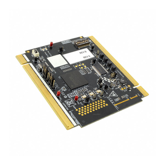
- Page 2 Quick Start Guide Get to Know the TWR-LCDC-EPSON c Options Primary Edge Connector External RGB Interface Epson S1D13513 Clock Options Configuration External LVDS Switches Interface External SPI Secondary Edge Connector SPI Options TWR-LCDC-EPSON Freescale Tower System The TWR-LCDC-EPSON module is part of the Freescale Tower System portfolio, a modular development platform that enables rapid prototyping and tool re-use through reconfigurable hardware.
- Page 3 TOWER SYSTEM Headline of Features in Initial Caps Can Go TWR-LCDC-EPSON Features to Two Lines If Necessary • Features the Epson S1D13513 display controller • Onboard SDRAM • Interfaces with a Tower System controller module via the parallel external memory interface (EBI) •...
-
Page 4: Learn More
Quick Start Guide Step-by-Step Installation Instructions Interact with the Assemble the Graphical User Interface Tower System The default example application features The default example application assumes a simple GUI developed using PEG and the following Tower assembly: TWR-ELEV featuring the CRTouch to provide + TWR-K60D100M + TWR-LCD-RGB + touch inputs. - Page 5 TOWER SYSTEM TWR-LCDC-EPSON Jumper Settings Jumper Option Setting Description Disables the onboard 27 MHz oscillator 27 MHz OSC Disable connected to S1D13513 OSCI2 Disables the onboard 10 MHz oscillator 10 MHz OSC Disable connected to S1D13513 CLKI3 Disables external LED Backlight (signals routed to J15 for off-board use) 3-4 short, 5-6 open, 7-8 open: 20 mA load External LED Back...
- Page 6 Quick Start Guide TWR-LCDC-EPSON Jumper Settings Continued Jumper Option Setting Description Inverts the S1D13513 GPIO0 signal (refer to the S1D1513 for usage details) SPI CS Inverter Enable Direct connection of the S1D13513 GPIO0 signal Unshunted: Rising edge data strobe External LVDS Data Strobe Polarity Shunted: Falling edge data strobe Routes the S1D13513 GPIO0 signal to JP1...
- Page 7 TOWER SYSTEM TWR-LCDC-EPSON Jumper Settings Continued Jumper Option Setting Description Routes the S1D13513 GPIO1 signal to JP1 (pin 2) for off-board use Routes the primary elevator SPI1 to the secondary elevator SPI2 SPI CLK Routing Configuration Routes the S1D13513 GPIO1 signal to secondary elevator SPI2 CLK Routes the primary elevator SPI1 CLK to JP1 (pin 2) for off-board use...
- Page 8 Quick Start Guide TWR-LCDC-EPSON Jumper Settings Continued Jumper Option Setting Description Routes the S1D13513 GPIO3 signal to JP1 (pin 2) for off-board use Routes the primary elevator SPI1 to the secondary elevator SPI2 SPI MISO Routing Configuration Routes the S1D13513 GPIO3 signal to secondary elevator SPI2 MISO Routes the primary elevator SPI1 MISO to JP1 (Pin 2) for off-board use...
- Page 9 TOWER SYSTEM TWR-LCDC-EPSON Switch Settings Switch Option Setting Description Reset Push Resets the S1D13513 Maps to S1D13513 CNF[0:4] (ON = 1 / OFF = 0) S1D13513 Host Bus Default setting for Tower System is [1:5] Interface Settings [On,On,On,Off,Off] Corresponding to Parallel Direct 68 bus interface Maps to S1D13513 CNF[5] S1D13513...
- Page 10 Quick Start Guide TWR-LCDC-EPSON Jumper Settings Continued Jumper Option Setting Description Maps to S1D13513 CNF[7:8] (ON = 1 / OFF = 0) Default setting for Tower System is [Off,On] [Off,Off] = Use CLKI3 clock source (refer to J3) S1D13513 PLL Clock [On,Off] = Use BUSCLK [8:9] Source...
- Page 11 TOWER SYSTEM Arrow.com. Arrow.com. Arrow.com. Arrow.com. Arrow.com. Arrow.com. Arrow.com. Arrow.com. Arrow.com. Arrow.com. Arrow.com. Downloaded from Downloaded from Downloaded from Downloaded from Downloaded from Downloaded from Downloaded from Downloaded from Downloaded from Downloaded from Downloaded from...
-
Page 12: Warranty
Freescale and the Freescale logo are trademarks of Freescale Semiconductor, Inc., Reg. U.S. Pat. & Tm. Off. Tower is a trademark of Freescale Semiconductor, Inc. All other product or service names are the property of their respective owners. © 2013 Freescale Semiconductor, Inc. Document Number: TWRLCDCEPSONQSG REV 0 Agile Number: 926-78734 REV A Arrow.com.
Need help?
Do you have a question about the NXP TWR-LCDC-EPSON and is the answer not in the manual?
Questions and answers