Table of Contents
Advertisement
Quick Links
Advertisement
Table of Contents

Related Manuals for Aerotech BA50 Series


Summary of Contents for Aerotech BA50 Series
-
Page 1: Ba50/75/100 Series Hardware Manual
BA50/75/100 Series Hardware Manual Revision:1.6... - Page 2 This manual contains proprietary information and may not be reproduced, disclosed, or used in whole or in part without the express written permission of Aerotech, Inc. Product names mentioned herein are used for identification purposes only and may be trademarks of their respective companies.
-
Page 3: Table Of Contents
Chapter 3: Technical Details 3.1. Electrical and Environmental Specifications 3.2. BA Amplifier Dimensions Chapter 4: Troubleshooting 4.1. Amplifier Related Problems 4.2. Fuse Replacement 4.3. Cleaning Appendix A: Warranty and Field Service Appendix B: Revision History Appendix C: Cable Drawings Index www.aerotech.com... -
Page 4: List Of Figures
Three-Phase Current Regulator Circuit Figure 3-1: BA50 Dimensions (Front View) Figure 3-2: BA50 Preferred Mounting (Side View) Figure 3-3: BA75/100 Dimensions (Front View) Figure C-1: BA Feedback Cable (PFC) Figure C-2: BA Series Light Duty Brushless Motor Cable (PMC) (BA 50 only) www.aerotech.com... -
Page 5: List Of Tables
DIP Switch Functions Table 1-4: Potentiometer Functions Table 1-5: Connector P1 Pinouts Table 2-1: Jumper Selections Table 3-1: Electrical Specifications per Model Table 3-2: Additional Electrical Specifications Table 4-1: Amplifier Faults, Causes, and Solutions Table 4-2: Fuse Replacement Part Numbers www.aerotech.com... - Page 6 Table of Contents BA50/75/100 Hardware Manual This page intentionally left blank. www.aerotech.com...
-
Page 7: Eu Declaration Of Conformity
BA50/75/100 Hardware Manual Hardware Manual Declaration of Conformity EU Declaration of Conformity Manufacturer Aerotech, Inc. Address 101 Zeta Drive Pittsburgh, PA 15238-2897 Product Brushless Servo Amplifier (BA50/75/100) Model/Types This is to certify that the aforementioned product is in accordance with the applicable requirements of the... -
Page 8: Agency Approvals
Declaration of Conformity BA50/75/100 Hardware Manual Hardware Manual Agency Approvals Aerotech, Inc. BA50/75/100 Series Amplifiers have been tested and found to be in accordance to the following listed Agency Approvals: Approval / Certification: CUS NRTL Approving Agency: TUV SUD America Inc. -
Page 9: Safety Procedures And Warnings
N O T E : Aerotech continually improves its product offerings; listed options may be superseded at any time. All drawings and illustrations are for reference only and were complete and accurate as of this manual’s release. - Page 10 7. All service and maintenance must be performed by qualified personnel. 8. This product is intended for light industrial manufacturing or laboratory use. Use of this product for unintended applications can result in injury and damage to the equipment. www.aerotech.com...
-
Page 11: Chapter 1: Introduction
Differential inputs are used for better noise immunity. Velocity feedback is from either an encoder or tachometer and logic inputs include directional current limits and shutdown. Fault, current, and velocity outputs simplify monitoring drive status. Figure 1-1: BA50/75/100 Series Amplifiers www.aerotech.com Chapter 1... -
Page 12: Table 1-1: Ba Models
Table 1-2: BA Models and Voltage Configurations Base “Power Input” Voltage Nominal Motor DC Output Cur- Output Current (Peak Model Range (VAC) Bus (VDC) rent (Peak) Continuous) BA50 200…240VAC 282…340VDC BA75 200…240VAC 282…340VDC BA100 200…240VAC 282…340VDC 100A Chapter 1 www.aerotech.com... -
Page 13: Ba Drive Package
200-240 VAC. The power supply is included with the standard package for offline operation without the need for an isolation transformer. Figure 1-2 shows the standard package configuration. Figure 1-2: Functional Diagram **AUX PWR INPUT "Control Power" applications, contact factory for this configuration. www.aerotech.com Chapter 1... -
Page 14: Hardware Overview And Function
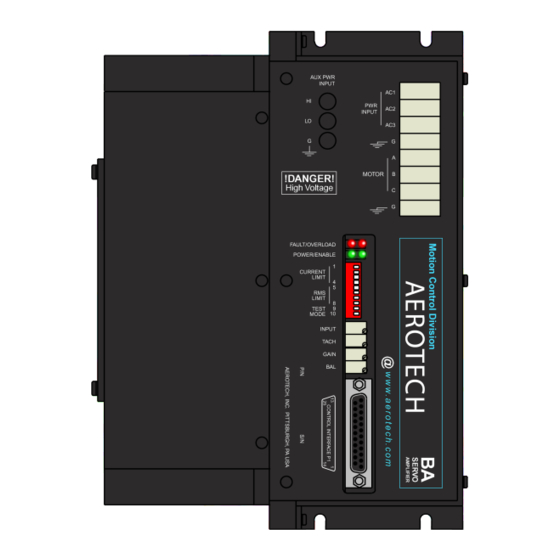
- or - “External Shunt Resistor” Motor and AC connector. Power Connections Contact factory for these configurations Fault/Overload LED Power/Enable LED DIP Switch Input Pot Tach Pot Gain Pot Balance Pot Connector P1 Figure 1-3: Amplifier Hardware Chapter 1 www.aerotech.com... -
Page 15: Motor And Ac Power Connections
Closing this position allows the Balance potentiometer to manually Test closed control motor velocity or torque without the need of an input signal depending upon the setting of switch 10. Velocity/Current mode - closing this position enables the current Mode mode. www.aerotech.com Chapter 1... - Page 16 Open switches 5, 6, and 7; close switch 8. Example for BA50 - Setting Current Limits To set the peak current to 37A: Peak Current (35A peak/50A max peak) x 100 = 75% Close switches 3 and 4; open switches 1 and 2. Chapter 1 www.aerotech.com...
-
Page 17: Potentiometers (Pots)
The unit must be powered down to clear the fault. In addition, the OVERLOAD LED energizes whenever the RMS current limit threshold is exceeded. If the RMS threshold is exceeded for more than two seconds, the drive becomes faulted and shuts down. www.aerotech.com Chapter 1... -
Page 18: Table 1-5: Connector P1 Pinouts
Recommended reference input for tachometer. This point is identical to input -tach signal common. Hall effect B. One of three commutation signals used with brushless input Hall B motors. Used in conjunction with Hall effect A and Hall effect C. Chapter 1 www.aerotech.com... - Page 19 2. Denotes a factory option for analog Hall commutation is available. When using analog Hall feedback, only Hall A and Hall B connections are used. 3. Denotes that pins 21, 9, 22, and 8 also function as differential inputs for phase A and phase B current commands, respectively (this is a factory option). www.aerotech.com Chapter 1...
-
Page 20: I/O Circuitry
+24VDC. Figure 1-4: Fault Output SHUTDOWN/ENABLE P1-10 .1 UF 74HC14 Figure 1-5: Enable/Shutdown Inputs 10K 1% +ILMT P1-11 10K 1% .1 UF 74HC14 10K 1% -ILMT P1-24 10K 1% .1 UF 74HC14 Figure 1-6: ± Limit Inputs Chapter 1 www.aerotech.com... -
Page 21: Figure 1-7: Hall And Encoder Inputs
10K 1% 10K 1% 10K 1% P1-4 10K 1% 74HC14 P1-16 10K 1% 74HC14 P1-17 10K 1% 100PF 100PF 100PF 74HC14 P1-18 SN75157 SIN-N .01UF P1-19 P1-5 SN75157 .01UF COS-N P1-6 Figure 1-7: Hall and Encoder Inputs www.aerotech.com Chapter 1... - Page 22 Introduction BA50/75/100 Hardware Manual This page intentionally left blank. Chapter 1 www.aerotech.com...
-
Page 23: Chapter 2: Installation And Configuration
Power stage drive signals are derived from B phase differential input (factory option). JP14 Current command configuration or tachometer feedback through pin 3 of P1 in the velocity loop configuration (default). Electronic tachometer signal derived from encoder signals in velocity loop configuration. www.aerotech.com Chapter 2... -
Page 24: Figure 2-1: Ba50/75/100 Board Assembly (Jumpers Shown In Default)
Signal common of control section connected to earth ground (default). Signal common, not referenced to earth ground. JP25 0° commutation offset (default). 30° commutation offset. JP26 0° commutation offset (default). 30° commutation offset. Figure 2-1: BA50/75/100 Board Assembly (Jumpers Shown in Default) Chapter 2 www.aerotech.com... -
Page 25: Wiring, Grounding, And Shielding Techniques
4. Providing a strong Protective Ground (PE) connection to the amplifier and motor creates a low impedance path to electrical noise that reduces radiated emissions and improves system performance. 5. If possible, do not route motor cables near cables carrying logic signals and use shielded cable to carry logic signals. www.aerotech.com Chapter 2... -
Page 26: Figure 2-2: Wiring To Minimize Emi And Capacitive Coupling
Installation and Configuration BA50/75/100 Hardware Manual Install Aerotech FBF-3 filter or 10 ferrite beads per wire at drive (Elna Fair-Rite #2643002402 or #2643250402) Motor Frame Figure 2-2: Wiring to Minimize EMI and Capacitive Coupling Chapter 2 www.aerotech.com... -
Page 27: Minimizing 50/60 Hz Line Interference
The path of current caused by this coupling between the motor frame and the amplifier stage passes through the current feedback sensing devices of the amplifier. Depending on the magnitude of this current, a 50/60 Hz torque disturbance may be present in the position loop. www.aerotech.com Chapter 2... -
Page 28: Figure 2-4: Isolation Transformer Connection (Eliminates Torque Disturbance)
To eliminate this problem, an isolation transformer can be used to block the 50/60 Hz from being seen by the motor frame. Refer to Figure 2-4 for connection of this transformer. 200 ... 240 VAC 50/60 Hz Figure 2-4: Isolation Transformer Connection (eliminates torque disturbance) Chapter 2 www.aerotech.com... -
Page 29: Integrated Configurations
In this configuration the amplifier closes and controls the velocity loop. Refer to Figure 2-5 for the velocity command configuration. This configuration can drive both brush and brushless DC motors. Figure 2-5: Velocity Command Configuration www.aerotech.com Chapter 2... -
Page 30: Current Command Configuration
2-6. The advantage to this configuration is the sine and cosine signals to the amplifier and a tachometer are not required. This configuration will also drive both brush and brushless DC motors. Figure 2-6: Current Command Configuration Chapter 2 www.aerotech.com... -
Page 31: Dual-Phase Command Configuration
The dual-phase inputs are sinusoidal and are 120° out of phase from each other. The third phase is generated by the amplifier. The dual-phase command configuration is shown Figure 2-7. The advantage to this configuration is that it provides the smoothest possible motion. Figure 2-7: Dual-Phase Command Configuration www.aerotech.com Chapter 2... -
Page 32: Control Connections
For most applications under the velocity command mode, the preferred starting point for setting the three gain pots is as follows: INPUT pot - 1/3 CW from full CCW TACH pot - full CW GAIN pot - full CW Chapter 2 www.aerotech.com... -
Page 33: Figure 2-8: Command Signal Adjustment Portion Of The Pre-Amplifier Circuit
JP3, JP5, JP15, and JP6 set to 1-2 (default) for brushless motor operation or 2-3 for brush motor operation For single ended command input, connect signal to P1-8 (+input) NOTE: and the P1-21 (-input) to signal common. Figure 2-8: Command Signal Adjustment Portion of the Pre-Amplifier Circuit www.aerotech.com Chapter 2... -
Page 34: Setup - Dual-Phase Command Mode
To setup the pre-amplifier circuit for use in the dual-phase mode, configure the BA amplifier as follows: JP11 and JP13 are set to 3-4 JP3, JP5, JP15, and JP6 are set to 1-2 (default) This mode is used with brushless motors only. Refer to Figure 2-7 for dual-phase command configuration. Chapter 2 www.aerotech.com... -
Page 35: Motor Phasing Process
“1” indicates five volts or logic high. N O T E : If an Aerotech brushless motor is used with the BA amplifier, motor phase and HALL connections can be easily determined by referring to the system interconnection drawings in... -
Page 36: Figure 2-9: Motor Phasing
Installation and Configuration BA50/75/100 Hardware Manual DEGREES COMMUTATION SEQUENCE (HALL A,B,C) 0° Commutation Waveforms (Aerotech Motors) 30° Commutation Waveforms Motor Amplifier +1/2A PHASE A -1/2A +1/2B PHASE B -1/2B +1/2C PHASE C -1/2C Motor Rotation Figure 2-9: Motor Phasing Chapter 2... -
Page 37: Current Regulator Adjustment
Phase C LM348 20.0K Voltage Command LM348 The sum of the current signals to phase IMPORTANT: A and B together should never exceed the maximum current rating of a single phase. Figure 2-10: Three-Phase Current Regulator Circuit www.aerotech.com Chapter 2... - Page 38 “A” current. For DC brush motor operation, this signal would represent the current flowing in the motor armature. The scale factor for current feedback on P1- 12 is 16.6 Amp/Volt for the BA100, 12.5 Amp/Volt for the BA75, and 8.3 Amp/Volt for the BA50. Chapter 2 www.aerotech.com...
-
Page 39: Chapter 3: Technical Details
8.5 lb (3.9 kg) Installation Overvoltage category Pollution Degree 1. Output Voltage is dependent on the AC supply input voltage. Examples: 200 VAC input power = approximately 282 VDC output. 240 VAC input power = approximately 340 VDC output www.aerotech.com Chapter 3... -
Page 40: Table 3-2: Additional Electrical Specifications
This allows the amplifier to close the servo loop and control the stability of the loop. Tachometer- Pin 15: Reference input for tachometer. This point is identical to signal common. Chapter 3 www.aerotech.com... - Page 41 Power: 8 terminal screw terminal for AC input and motor output. Gain: adjusts preamp AC gain. BALance: nulls command input DC offsets. Potentiometers Tach: adjusts gain of tach or encoder derived velocity feedback input. Input: adjusts gain of command input. www.aerotech.com Chapter 3...
- Page 42 LED indicator drive fault (red). Refer to Protective Features above. (fault) Indicator LED indicator RMS overload (red). Energized when RMS limit is exceeded. Will generate a 'fault' if limit is exceeded for more than two seconds. (overload) Chapter 3 www.aerotech.com...
-
Page 43: Ba Amplifier Dimensions
The outline dimensions for the BA amplifiers are shown in Figure 3-1 Figure 3-2. BA50 Preferred Mounting (Side View). To ensure proper heat dissipation, Aerotech recommends the following procedures. 1. Use the mounting procedure shown in Figure 3-1, Figure 3-2, and Figure 3-3. -
Page 44: Figure 3-1: Ba50 Dimensions (Front View)
Technical Details BA50/75/100 Hardware Manual 241.3 [9.50] 2.5 [.10] 50.8 [2.00] 24.1 [.95] 92.7 [3.65] Dimensions: Millimeters [Inches] Figure 3-1: BA50 Dimensions (Front View) Chapter 3 www.aerotech.com... -
Page 45: Figure 3-2: Ba50 Preferred Mounting (Side View)
1 ft 26.8 [1.05] 206.8 [8.14] 5.5 [.22] 4.8 [.19] Typ. Typ. 13.0 [.51] 64.8 [2.55] 2 ft 217.9 [8.58] 152.4 [6.00] Typ. 28.6 [1.12] Typ. Dimensions - Millimeters [Inches] Figure 3-2: BA50 Preferred Mounting (Side View) www.aerotech.com Chapter 3... -
Page 46: Figure 3-3: Ba75/100 Dimensions (Front View)
Technical Details BA50/75/100 Hardware Manual 92.7 [3.65] 2.5 [.10] 11.7 [.46] 241.3 [9.50] 217.9 [8.58] 231.4 [9.11] Typ. 24.1 [.95] 50.8 [2.00] Dimensions: Millimeters [Inches] Typ. Typ. BA100 85.9 [3.38] Figure 3-3: BA75/100 Dimensions (Front View) Chapter 3 www.aerotech.com... -
Page 47: Chapter 4: Troubleshooting
PC board and at the input and output power connections. A qualified ser- vice technician or electrician should perform these tests. W A R N I N G : Hazardous voltages may be present up to eight minutes after power is disconnected www.aerotech.com Chapter 4... -
Page 48: Table 4-1: Amplifier Faults, Causes, And Solutions
2. Over temperature condition - Turn off and let amplifier cool down. Provide energizes). better ventilation. 3. Defective on board power supply - Return for repair. 4. Over loaded logic power supply - Remove external device(s) being powered from the BA 5 V supply. Chapter 4 www.aerotech.com... -
Page 49: Fuse Replacement
BA50/75/100 Hardware Manual Troubleshooting 4.2. Fuse Replacement Table 4-2 lists the replacement fuse part numbers (both Aerotech and manufacturer). Additional fuse information may be described in other documentation. Table 4-2: Fuse Replacement Part Numbers Fuse Manufacture P/N Aerotech P/N 3A, MDA (F1 shunt) Buss; MDA-3... - Page 50 Troubleshooting BA50/75/100 Hardware Manual This page intentionally left blank. Chapter 4 www.aerotech.com...
-
Page 51: Appendix A: Warranty And Field Service
Aerotech makes no warranty that its products are fit for the use or purpose to which they may be put by the buyer, whether or not such use or purpose has been disclosed to Aerotech in specifications or drawings previously or subsequently provided, or whether or not Aerotech’s... - Page 52 Aerotech's approval. On-site Warranty Repair If an Aerotech product cannot be made functional by telephone assistance or by sending and having the customer install replacement parts, and cannot be returned to the Aerotech service center for repair, and if Aerotech determines the problem could be warranty-related, then the following policy applies:...
-
Page 53: Appendix B: Revision History
BA50/75/100 Hardware Manual Revision History Appendix B: Revision History Revision Description Agency Approvals and Declaration of Conformity have been added. Revision changes have been archived. If you need a copy of this revision, contact Aerotech Global Technical Support. 1.0a www.aerotech.com Appendix B... - Page 54 Revision History BA50/75/100 Hardware Manual This page intentionally left blank. Appendix B www.aerotech.com...
-
Page 55: Appendix C: Cable Drawings
BA50/75/100 Hardware Manual Cable Drawings Appendix C: Cable Drawings The following section provides the user with reference drawings for connecting Aerotech cables to the BA amplifiers. Figure C-1: BA Feedback Cable (PFC) Figure C-2: BA Series Light Duty Brushless Motor Cable (PMC) (BA 50 only) www.aerotech.com... - Page 56 Cable Drawings BA50/75/100 Hardware Manual This page intentionally left blank. Appendix C www.aerotech.com...
-
Page 57: Index
Hall and Encoder Inputs Circuitry Current Regulator Adjustment Hall Connections Hall Effect Device Declaration of Conformity Hardware Differential input Function DIP Switch 14-15 Overview Functions Drive Package I/O Circuitry Dual Phase Command 29,31 IFDBK Dual Phase Command Mode INPUT Pot www.aerotech.com Index... - Page 58 Velocity 15,29 Motor Phasing Velocity Command Velocity Command Mode Noise Voltage Configurations Back-Propagation Wiring Techniques Operating modes Options OVERLOAD LED Phase Hall Sequence Potentiometer Functions Potentiometers 14,17 Power Power Connections 14-15,32 POWER LED Pre-amplifier circuit Product Overview RCN1 Index www.aerotech.com...
Need help?
Do you have a question about the BA50 Series and is the answer not in the manual?
Questions and answers