Table of Contents
Advertisement
Quick Links
Advertisement
Table of Contents

Related Manuals for Ihse kvm-tec MAXflex MA


Summary of Contents for Ihse kvm-tec MAXflex MA
- Page 1 MAXflex Single Copper KT - 6014 SET MA -Set MAXflex Dual Copper kvm-tec KT - 6024 SET MA2Set MAXflex Single Fiber KT - User 6016 MA-F Set Manual MAXflex Dual Fiber KT - 6026 Fiber MA2-F Check out our Installation Channel: www.kvm-tec.com Misprints, errors and technical changes reserved...
- Page 2 COMPATIBILITY kvm-tec Extender Compatibility kvm-tec Extender Compatibility remote Remote Easyline Flexline Scalableline Matrixline Ultraline media4Kconnect Gateway2GO Easyline not scalable ECOsmart Flexline only Maxflex is scalable media4Kconnect not scalable media4Kconnect not scalable SPECIAL media4Kconnet not scalable 12G SDI Scalableline Full HD Scalableline scalable Matrixline...
-
Page 3: Table Of Contents
TABLE OF CONTENT 1. Introduction 1.1 Intended use 1.2 Safety Instructions 1.3 Technical Specifications 1.4 MAXflex extender single copper 1.5 MAXflex extender dual copper 1.6 MAXflex extender single fiber 1.7 MAxflex Extender Dual Fiber 1.8 Productelements MAXflex backpanel 1.9 About the status LED 2. - Page 4 TABLE OF CONTENT 2.9 Replacing the SFP module 2.10 Removing a CATx cable 2.11 Removing a fiber cable 2.12 Best practice for Windows 10 3. Extender settings 3.1 Using the on screen menu 3.2 System Status 3.3 Viewing the current firmware version 3.4 Features menu 3.4.1 Point to Point 3.4.2 Matrix Switching Mode...
- Page 5 TABLE OF CONTENT 3.6.3. USB Remote wake up 3.6.4 Compatibility with Linux 3.6.5 Bandwidth reduction 3.6.6 VGA Parameters 3.7 Remote Settings 3.7.1 Editing a keyboard layout 3.7.2 Editing keyboard shortcuts 3.7.3 Setting the audio volume 3.7.4 Setting a baud rate for your RS232 connection 3.7.5 USB share any key 3.7.6 Using the power saving mode 3.7.7 Hiding system status menu...
- Page 6 TABLE OF CONTENT 4.2 PUSH / GET List 4.3 Favorite list 4.4 Connecting, disconnecting or selecting a current workplace connected devices 4.5 Searchbox-function 4.6 IP Management 5. Troubleshooting & First Aid 6. Maintance and care 6.1 EXTENDER CARE 6.2 Disposal 7.
-
Page 7: Introduction
1. INTRODUCTION 1. INTRODUCTION Congratulations on the purchase of your new MAXflex MA/MA-F KVM Extender. You have bought a high quality extender. These instructions are part of this product. They contain important information regarding safety, use and disposal for every user of the MAXflex MA and MA-F KVM Extender. -
Page 8: Safety Instructions
1. INTRODUCTION 1.2 SAFETY INSTRUCTIONS WARNING! Read and understand all safety instructions. • Follow all the instructions. This will avoid accidents, fire, explosions, electric shocks or other hazards that may result in damage to property and/or severe or fatal injuries. Please ensure that everyone who uses the product has read and followed these warnings and instructions. - Page 9 1. INTRODUCTION • Protect cables from being strained, pinched or buckled and place them in a way to prevent people from tripping over the cord. • In particular, ensure to avoid damage to the mains adapter. • Use the product with a suitable, properly installed and easily accessible mains power socket.
-
Page 10: Technical Specifications
1. INTRODUCTION 1.3 TECHNICAL SPECIFICATIONS Type: KVM Extender (local unit and remote unit) Model: MAXflex MA and MAXflex Fiber MA-F KVM Extender Power supply input voltage: 100 - 240 V; 50/60 Hz AC Power supply output: 12V; 1A (external power supply) Power requirement: 6W per extender (excluding attached USB devices) Operating temperature range:... -
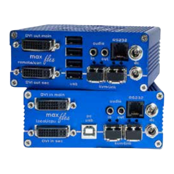
Page 11: Maxflex Extender Single Copper
1. INTRODUCTION 1.4 MAXFLEX EXTENDER SINGLE COPPER Local Extender (CPU) Name Function dvi-out DVI conenction to monitor dvi - in DVI conection to PC USB to PC audio in Audio in from PC audio out Audio out to PC kvm-link Network cable redundant kvm-link Network cable... - Page 12 1. INTRODUCTION Remote Extender (CON) Name Function DVI out DVI to monitor . USB from keyboard and mouse kvm-link connection for CAT5/6/7 cable redundant kvm-link connection for CAT5/6/7 cable connection for 12V 1A power supply redundant connection for 12V 1A power supply RS232 RS232 connection audio out...
-
Page 13: Maxflex Extender Dual Copper
1. INTRODUCTION 1.5 MAXFLEX EXTENDER DUAL COPPER Local Extender (CPU) Name Function dvi-in second DVI connection to monitor dvi - in main DVI connection to monitor USB to PC kvm-link Network cable kvm-link Network cable connection for 12V 1A power supply redundant connection for 12V 1A power supply RS232 RS 232 connection... - Page 14 1. INTRODUCTION Remote Extender (CON) Name Function DVI out second DVI connction to monitor . dvi- out main DVI connction to monitor . USB from keyboard and mouse kvm-link Connection for CAT5/6/7 cable kvm-link Connection for CAT5/6/7 cable connection for 12V 1A power supply redundant connection for 12V 1A power supply RS232 RS232 connection...
-
Page 15: Maxflex Extender Single Fiber
1. INTRODUCTION 1.6 MAXFLEX EXTENDER SINGLE FIBER Local Extender (CPU) Name Function dvi-out DVI connection to monitor dvi-in DVI connection from PC USB to PC kvm-link Network cable redundant kvm-link Network cable connection for 12V 1A power supply redundant connection for 12V 1A power supply RS232 RS 232 connection audio out... - Page 16 1. INTRODUCTION Remote Extender (CON) Name Function DVI out DVI connection to monitor . USB from keyboard and mouse kvm-link connection for Fiber cable redundant kvm-link connection for Fiber cable connection for 12V 1A power supply redundant connection for 12V 1A power supply RS232 RS232 connection audio out...
-
Page 17: Maxflex Extender Dual Fiber
1. INTRODUCTION 1.7 MAXFLEX EXTENDER DUAL FIBER Local Extender (CPU) Name Function dvi-in second DVI connection to monitor dvi-in main DVI conenction to monitor USB to PC kvm-link Connection for Fiber cable kvm-link Connection for Fiber cable Connection for 12V 1A power supply redundant Connection for 12V 1A power supply RS232 RS 232 connection... - Page 18 1. INTRODUCTION Remote Extender (CON) Name Function DVI out DVI to Monitor . DVI out DVI connection to Monitor USB from keyboard and mouse kvm-link Connection for Fiber cable kvm-link Connection for Fiber cable Connection for 12V 1A power supply redundant Connection for 12V 1A power supply RS232 RS232 conenction...
-
Page 19: Productelements Maxflex Backpanel
1. INTRODUCTION 1.8 PRODUCTELEMENTS MAXFLEX BACKPANEL BACKSIDE Name Function LED Status Display of LED Status Reset Button for Reset kvm-tec | 19 Misprints, errors and technical changes reserved... -
Page 20: About The Status Led
1. INTRODUCTION 1.5 ABOUT THE STATUS LED LED Status Update: Farbe Anzeige des Lichtes Autoupdate Modus fast flashing Update runs shining Update failed shining Update successful Meaning LED displays Farbe Anzeige des Lichtes Bedeutung shining only network connection available fast flashing No active connection shining No video signal... -
Page 21: Installation Extender
2. INSTALLATION EXTENDER 2.1 UNPACKING AND CHECKING THE CONTENTS Before using the product for the first time it should be checked for damage. In case of damage due to transport inform the carrier immediately. Before delivery the product is checked for its function and its operating safety. - Page 22 2. INSTALLATION EXTENDER Make sure that the packaging contains the following content: MAXflex single Fiber Delivery Content - Local (CPU) 1 x MA1-F local (CPU) 1 x wall power supply unit l 12V 1A (EU-plug or INT. plug) 1 x DVI - DVI cable 1, 8m/5.9ft 1 x USB cable 1, 8m/5.9 ft.
-
Page 23: Mounting Options
2. INSTALLATION EXTENDER 2.2 MOUNTING OPTIONS 2.2.1 MOUNTING PADS AND RUBBER FEET The mounting pads and rubber feet can be used to hold the extenders in place and prevents them from sliding and falling. To attach the mounting pads or rubber feet: 1. -
Page 24: Installing The Extender
2. INSTALLATION EXTENDER 2.3 INSTALLING THE EXTENDER WARNING! Read and understand all safety information before installing the product. The units can be set up to access one host computer, or to access numerous host computers. In the case of the latter, an additional Network Switch must be installed. With a Network Switch, each user can gain quick access to any of the required computers. -
Page 25: Quick Installation Maxflex Single
2. INSTALLATION EXTENDER 2.4 QUICK INSTALLATION MAXFLEX SINGLE local / CPU – remote / CON Power plug 12V 1A Power plug 12V 1A (redundant) Network cable CAT5e6/7/ up to 150m/492ft main link Network cable CAT5e/6/7/ up to 150m/492ft (redundant) Connect the CON / Remote and the CPU / Local Unit to the included 12V 1A power supply. -
Page 26: Quick Installation Maxflex Dual
2. INSTALLATION EXTENDER 2.5 QUICK INSTALLATION MAXFLEX DUAL local / CPU – remote / CON USB from Power plug Keyboard and mouse 12V 1A Power plug 12V 1A (redundant) Network cable CAT5e6/7/ up to 150m/492ft main link Network cable CAT5e/6/7/ up to 150m/492ft Connect the CON / Remote and the CPU / Local Unit to the included 12V 1A power supply. -
Page 27: Quick Installation Maxflex Single Fiber
2. INSTALLATION EXTENDER 2.6 QUICK INSTALLATION MAXFLEX SINGLE FIBER local / CPU – remote / CON Power plug 12V 1A Power plug 12V 1A (redundant) OM3-Fiber cable up to 500m/1640ft main link OM3-Fiber cable up to 500m/1640ft (redundant) 1. Connect the CON / Remote and the CPU / Local Unit to the included 12V 1A power supply. -
Page 28: Quick Installation Maxflex Dual Fiber
2. INSTALLATION EXTENDER 2.7 QUICK INSTALLATION MAXFLEX DUAL FIBER local / CPU – remote / CON USB from Power plug Keyboard and mouse 12V 1A Power plug 12V 1A (redundant) OM3-Fiber cable up to 500m/1640ft main link OM3-Fiber cable up to 500m/1640ft Connect the CON / Remote and the CPU / Local Unit to the included 12V 1A power supply. -
Page 29: Start Up
2. INSTALLATION EXTENDER 2.8 START UP To start up the system without switch: 1. Make sure that the two monitors and the computer are switched on. 2. If you are using a Network Switch, connect the power supply to an earthed wall socket. 3. -
Page 30: Removing A Catx Cable
2. INSTALLATION EXTENDER 2.10 REMOVING A CATX CABLE To remove a CATx cable: • Press the latch down and slowly pull the cable out. 2.11 REMOVING A FIBER CABLE To remove a fiber cable: • Press the latch down and slowly pull the cable out. 30 | kvm-tec Misprints, errors and technical changes reserved... -
Page 31: Best Practice For Windows 10
2. INSTALLATION EXTENDER 2.12 BEST PRACTICE FOR WINDOWS 10 Disable USB Energy Savings in Windows 10 kvm-tec | 31 Misprints, errors and technical changes reserved... - Page 32 2. INSTALLATION EXTENDER 32 | kvm-tec Misprints, errors and technical changes reserved...
- Page 33 2. INSTALLATION EXTENDER kvm-tec | 33 Misprints, errors and technical changes reserved...
-
Page 34: Extender Settings
3. EXTENDER SETTINGS 3.1ACCESS TO THE MAIN MENU Use the monitor and keyboard to access the main menu Access to the main menu (main menu): 1. Make sure the extenders, monitors and computers are turned on. 2. Press the Alt Gr key five times quickly. The main menu and an overview of the an overview of the submenus is displayed. -
Page 35: System Status
3. EXTENDER SETTINGS 3.2 SYSTEM STATUS Single Dual In the status overview menu the current status of the extender connection is displayed. It provides information on the connection itself as well as resolution of the video channel, and USB- status. The enabled options and the current firmware-version is displayed in the left top corner. -
Page 36: Viewing The Current Firmware Version
3. EXTENDER SETTINGS 3.2 FIRMWARE VERSION DISPLAY Make sure that the main menu is open. Under „A“ - About the currently installed firmware version of the remote (CON) and local (CPU) extender is displayed (e.g. ‚4267‘). 3.3 FEATURES MENU Press the F key to enter the Features menu. Features Menu Point to Point Mode Enabled/Disabled... -
Page 37: Point To Point
3. EXTENDER SETTINGS 3.4.1 POINT TO POINT You can switch the Point to Point mode on and off by pressing the „P“ key ATTENTION - if the point to point mode is activated, the switching mode cannot be activated 3.4.2 MATRIX SWITCHING MODE By pressing the „M“... -
Page 38: Display The Last Received Image „Freeze Last Image
3. EXTENDER SETTINGS 3.4.4 DISPLAY THE LAST RECEIVED IMAGE „FREEZE LAST IMAGE“ With the „ freeze the last image“ function, the last image received can be displayed instead of a black screen when the remote extender (CON) is disconnected from the local extender (CPU). To show that it is the last image received, the frame of the image will blink red. -
Page 39: Usb Emulation Mode
3. EXTENDER SETTINGS 3.4.5 USB EMULATION MODE When this mode is set, the local extender emulates a keyboard and mouse always connected to the PC. The result is switching from one PC to another PC without any switching delay. Emulation Mode is restricted to mouse and keyboard only. 3.4.6 POWER REDUNDANCE ALERT AND LINK REDUNDANCE ALERT Our Masterflex and Maxfles single devices are redundant. -
Page 40: Diagnosis Menu
3. EXTENDER SETTINGS 3.4.7 DIAGNOSIS MENU In the Diagnosis menu, the runtimes of the individual connected channels are displayed. Both Remote Unit and Partner Local Unit are listed. Additionally you get the CPU temperature information of both units. Another feature is the cable test 40 | kvm-tec Misprints, errors and technical changes reserved... - Page 41 3. EXTENDER SETTINGS As soon as a connection to the partner has been established, the test can be started with the „Enter“ key or the arrow key on the right „→“. After a valid synchronization process, the test is started and the test run time and errors are displayed.
-
Page 42: Ddc Menu
3. EXTENDER SETTINGS 3.5 DDC MENU The DDC Information menu allows the user to specify which DDC information is used by the PC. Definition of the DDC information used by the PC: 1. make sure that the main menu is open. Press the D button and the DDC option menu will be displayed. -
Page 43: Ddc Main (Single)
3. EXTENDER SETTINGS 3.5.1 DDC MAIN (SINGLE) kvm-tec | 43 Misprints, errors and technical changes reserved... -
Page 44: Ddc Second (Dual)
3. EXTENDER SETTINGS 3.5.2 DDC SECOND (DUAL) 44 | kvm-tec Misprints, errors and technical changes reserved... -
Page 45: Extender Settings
3. EXTENDER SETTINGS 3.6 EXTENDER SETTINGS The Extender Settings menu allows the user to change a number of other settings. Select one of the three options (VGA, Audio and RS232) to enter the submenu. The other four can be activated or deactivated by pressing the corresponding button. Display the Extender Settings menu: 1.Make sure that the main menu is open. -
Page 46: Local Settings
3. EXTENDER SETTINGS 3.6.1 LOCAL SETTINGS View the local or remote Extender settings: - Press the L button to display the Local Setting menu. View the local or remote Extender settings: - Press the L button to display the Local Setting menu. USB Compatibility Mode Disabled/Enabled USB Remote Wakeup... -
Page 47: Usb Compatibility Mode
3. EXTENDER SETTINGS 3.6.2 USB COMPATIBILITY MODE Some PC‘s require a USB FullSpeed (USB 1.1) connection at startup. Our extenders are detected as USB HUB‘s - this may cause some PC‘s to abort the boot process. This can be avoided with the USB Compatibility Mode. The USB compatibility mode can be enabled or disable . -
Page 48: Usb Remote Wake Up
3. EXTENDER SETTINGS 3.6.3. USB REMOTE WAKE UP The PC can be set into sleep mode and can be reactivated with any key. 48 | kvm-tec Misprints, errors and technical changes reserved... -
Page 49: Compatibility With Linux
3. EXTENDER SETTINGS 3.6.4 COMPATIBILITY WITH LINUX Older Linux (before 2010) versions may not recognize the keyboard. In this case please activate the Linux compatibility mode 3.6.5 BANDWIDTH REDUCTION Here the bandwidth can be reduced. The basic setting is 0! You can change the bandwidth with +/- or u/d. -
Page 50: Vga Parameters
3. EXTENDER SETTINGS 3.6.6 VGA PARAMETERS The VGA settings can be adjusted and optimized. Optimize the VGA settings: 1. press the L button in the Extender Settings menu. The Local Settings menu is displayed. Press the V. The VGA menu will be displayed - Pressing F1 moves the display range upwards. -
Page 51: Remote Settings
3. EXTENDER SETTINGS VGA-1 Parameters 3.7 REMOTE SETTINGS • Press the R button to display the Remote Setting menu. kvm-tec | 51 Misprints, errors and technical changes reserved... -
Page 52: Editing A Keyboard Layout
3. EXTENDER SETTINGS 3.7.1 EDITING A KEYBOARD LAYOUT The Keyboard Local menu lets you switch between keyboard layouts for navigating the on screen display menu (OSD). You can choose between French (FR), English (EN) and German (DE). Selcting a keyboard layout: 1. -
Page 53: Editing Keyboard Shortcuts
3. EXTENDER SETTINGS 3.7.2 EDITING KEYBOARD SHORTCUTS You can change the keyboard shortcuts for common commands. You can choose your scroll speed. Edit shortcuts and change scroll speed on the Keyboard Shortcuts screen. To edit the shortcuts: 1. From the Extender Settings menu, press the R key. The Remote Settings menu appears. 2. -
Page 54: Setting The Audio Volume
3. EXTENDER SETTINGS 3.7.3 SETTING THE AUDIO VOLUME The volume of the audio input (microphone) on the remote unit can be changed. The default value is 5 but can be set to any value in between 0 and 9. At 0 the audio input on the remote unit is disabled. -
Page 55: Setting A Baud Rate For Your Rs232 Connection
3. EXTENDER SETTINGS 3.7.4 SETTING A BAUD RATE FOR YOUR RS232 CONNECTION Setting the baud rate with activated RS232 upgrade In the extender settings menu, press the R button. The Remote Settings Menu is displayed. Press the R button. 2. The Baud Rate menu is displayed. To select a baud rate, press the corresponding key. - Page 56 3. EXTENDER SETTINGS RS232 CONNECTOR PINNING Local Unit (CPU) Pinout (DCE): Remote Unit (CON)Pinout (DTE): Function direction Function direction — — The pin numbers refer to a 9-pin D-sub plug. The baud rate can be set in the menu. There is a universal setting for baud rates up to 9600 which transmits all different RS232 configurations transparently.
-
Page 57: Usb Share Any Key
3. EXTENDER SETTINGS 3.7.5 USB SHARE ANY KEY By pressing the button „B“ the USB Share any Key mode can be activated or deactivated. If the USB share any key, the USB function can be taken over with any key. If the function is deactivated, this works with the predefined hotkeys ( see 3.7.2.) kvm-tec | 57 Misprints, errors and technical changes reserved... -
Page 58: Using The Power Saving Mode
3. EXTENDER SETTINGS 3.7.6 USING THE POWER SAVING MODE In power save mode, the Extender can switch off the video output. The power off delay can be set or deactivated as desired in the Power Save Setting menu. To return from power save mode, press any key. Enable and disable power save mode on the remote screen. -
Page 59: Hiding System Status Menu
3. EXTENDER SETTINGS 3.7.7 HIDING SYSTEM STATUS MENU Press N in the Remote Settings menu. This will remove the status screen and the image remains black. kvm-tec | 59 Misprints, errors and technical changes reserved... -
Page 60: Change Keyboard Fallback Modus
3. EXTENDER SETTINGS 3.7.8 CHANGE KEYBOARD FALLBACK MODUS To use the OSD menu, the keyboard on the remote device must be identified. For most keyboards, use the 0 setting. When using USB, some mice act like a keyboard. In this case, select fallback mode 1 or 2. 60 | kvm-tec Misprints, errors and technical changes reserved... -
Page 61: Lock Menu
3. EXTENDER SETTINGS 3.7.9 LOCK MENU This menu protects the OSD control and after 5 minutes the OSD can no longer be activated. kvm-tec | 61 Misprints, errors and technical changes reserved... -
Page 62: Mouse Speed
3. EXTENDER SETTINGS 3.7.10 MOUSE SPEED Can be used in USB Emulation mode, Mouse glide & Switch and Multiview Commander. With this function the horizontal and vertical speed can be adjusted 3.7.11 MONITOR SYNC STRENGTH The frame start of the monitor is synchronized with the graphic card. Some monitors are very sensible regarding frequency changes. - Page 63 3. EXTENDER SETTINGS Single Dual kvm-tec | 63 Misprints, errors and technical changes reserved...
-
Page 64: Firmware Update
3. EXTENDER SETTINGS 3.8 FIRMWARE UPDATE 3.8.1 UPDATING A FIRMWARE WITH SWITCHING MANAGER Update management is carried out via the Switching Manager software included in the delivery see User Manual Switching Manager 2000 chapter 10.2 In this view, all extenders for which a firmware update is to be performed are displayed. This function displays a list of the extenders that are assigned to the Switching Manager. -
Page 65: Firmware Update With Usb Stick
3. EXTENDER SETTINGS 3.8.2 FIRMWARE UPDATE WITH USB STICK For the update with an USB stick the follwoing steps are necessary 1. you receive the message that you can plug in the USB stick. 2. copy the update file (ending in .kvm) to the USB stick 3. - Page 66 3. EXTENDER SETTINGS 66 | kvm-tec Misprints, errors and technical changes reserved...
-
Page 67: About This Device
3. EXTENDER SETTINGS 3.9 ABOUT THIS DEVICE By pressing the „A“ button, or by selecting the arrow keys, you can access the info menu, where you can obtain information about hardware and software versions, as well as the activated upgrades. You can also see the current firmware version here. single dual kvm-tec | 67... -
Page 68: Network Settings
4. NETWORK SETTINGS 4. NETWORK SETTINGS AND MANAGEMENT SWITCHING SYS- TEMS All network settings, user administration and extender management are done via the included Switching Manager software and all functions are described in the Switching Manager 2000 manual. You can download the manual from our website. www. kvm-tec.com 4.1 DISPLAY SWITCHING LIST Available devices that the user can connect to are displayed here. -
Page 69: Push / Get List
4. NETWORK SETTINGS 4.2 PUSH / GET LIST Display of all extenders that can be shared. The current image of the workstation can be shared with other remote units via this list kvm-tec | 69 Misprints, errors and technical changes reserved... -
Page 70: Favorite List
4. NETWORK SETTINGS 4.3 FAVORITE LIST A total of 8 favourites can be defined. The connection of these 8 favourites is possible with shortcuts from 1-8 70 | kvm-tec Misprints, errors and technical changes reserved... -
Page 71: Connecting, Disconnecting Or Selecting Acurrent Workplace Connected Devices
4. NETWORK SETTINGS 4.4 CONNECTING, DISCONNECTING OR SELECTING A CURRENT WORKPLACE CONNECTED DEVICES Logging in to the local PC in the main menu, press A. Enter your username and password. Disconnecting from an encoder in the main menu, press D. Enabling a direct connection If you are not connected through a network switch, you can connect directly to an encoder with point-to-point mode. -
Page 72: Searchbox-Function
4. NETWORK SETTINGS 4.5 SEARCHBOX-FUNCTION In the list view you can search for the different extenders In the list view you can see all available extenders. To search for specific Extenders, you must press the „TAB“ key. Now you can enter a string to search for the Extender you want to see. -
Page 73: Ip Management
4. NETWORK SETTINGS 4.6 IP MANAGEMENT The KVM extenders from kvm-tec support three different addressing methods. The IP Manage- ment menu is only accessible in the active “Matrix Switching Mode” under Features. Default In default mode, each Extender generates an IP address using the ID number to avoid number collisions in the network. - Page 74 4. NETWORK SETTINGS DHCP The KVM extenders from kvm-tec support the DHCP protocol (Dynamic Host Configuration Protocol). This allows the assignment of network addresses by a DHCP server. Static IP In Static-IP mode the IP addresses can be assigned via the OSD. It is necessary to be connected to a local partner to be able to transmit IP addresses.
- Page 75 4. NETWORK SETTINGS If all four IP addresses are overwritten, “Save/send settings” must be used to transmit the new values to the extenders. Static IP addresses can only be overwritten in Static IP mode. kvm-tec | 75 Misprints, errors and technical changes reserved...
-
Page 76: Troubleshooting & First Aid
5. TROUBLESHOOTING & FIRST AID Error Cause Solution LED is not The devices get no Is the power supply connected? (white box) lighting power LED is light in No connection Check if the RJ45/network cable is connected well. between Loc and (Clicking noise when plugging in) Control local and remote , if it does not work - please send an e-mail to support@kvm-tec.com... - Page 77 5. TROUBLESHOOTING & FIRST AID First smart connection Video error (stripes No Power USB is not working in the picture) No Video (No LED) Are the USB Check if all Check if all Check the Devices plugged in cables are plugged in cables are plugged in powerplug correctly?
-
Page 78: Maintance And Care
6. MAINTANCE AND CARE 6. MAINTANCE AND CARE 6.1 EXTENDER CARE Caution! Do not use solvent-containing cleaners. Do not use wipes, alcohols (e.g. spiritus) or chemicals as these could damage the surface. 6.2 DISPOSAL This symbol on the product, the accessories or packaging indicates that this product must not be treated as unsorted municipal waste, but must be collected separately! Dispose of the product via a collection point for the recycling of waste electrical and electronic equipment within the EU and in other European... -
Page 79: Warranty
7. WARRANTY 7. WARRANTY 7.1 STANDARD WARRANTY The warranty period is 24 months from the date of purchase. The warranty expires in case of: • External effort • improper maintenance • Violation of the operating instructions • lightning damage Please, contact us first before returning the product. 7.2 EXTENDED WARRANTY 2 years standard warranty Art Nr KT - 9003 warranty extension to 5 years... -
Page 80: Requirements For Cable
8. REQUIREMENTS FOR CABLE 8.1 REQUIREMENTS FOR CAT5E/6/7 CABLES A Cat5e/6/7 cable should meet the following requirements: • The pins are connected 1:1. Caution: the cable pairs must be twisted to EIA/TIA- 568A (rare) or EIA/TIA-568 B (common) pairs. • Erroneous assignments cannot be found with a simple cable tester. -
Page 81: Requirements Fiber Cables
8. REQUIREMENTS FOR CABLE 8.2 REQUIREMENTS FIBER CABLES 8.2.1 MULTI-MODE (STANDARD) A Multi-Mode fiber cable should meet the following requirements: • Maximum length should be 500 m. The MA1-F includes a fiber Multimode – SFP Module which allows a transmission distance of up to 500 m. •... -
Page 82: Requirements Network- Switch
9. REQUIREMENTS NETWORK- SWITCH 9. REQUIREMENTS NETWORK SWITCH The entire switching network system requires its own separate network. For security reasons, it cannot be integrated into an existing corporate network. The network switch must meet the following specifications: 1 Gigabit switch, with a port-to-port transfer rate of 1 Gigabit/second. The following switches have all been tested and verified to work with all kvm-tec extenders. -
Page 83: Address & Phone / Emails
Fax: 0043 (0) 2253 81 912 99 Email: support@kvm-tec.com Web: www.kvm-tec.com Find our newest updates and FAQs on our homepage: https://www.kvm-tec.com/en/support/overview-support/ KVM-TEC IHSE GmbH IHSE USA LLC IHSE GMBH Asia IHSE China Co.,Ltd Gewerbepark Benzstr.1 1 Corp.Dr.Suite 158Kallang Room 814... -
Page 84: Notes
11. NOTES 84 | kvm-tec Misprints, errors and technical changes reserved...
Need help?
Do you have a question about the kvm-tec MAXflex MA and is the answer not in the manual?
Questions and answers