Table of Contents
Advertisement
Quick Links
Advertisement
Table of Contents

Related Manuals for Ihse kvm-tec FLEXLINE SMARTflex KT-6011


Summary of Contents for Ihse kvm-tec FLEXLINE SMARTflex KT-6011
- Page 1 FLEXLINE smart flex FLEXLINE KT-6011 SET SMARTflex single in copper KT-6011L CPU/LOCAL KT-6011R CON/REMOTE kvm-tec KT-6021 SET SMARTflex dual in copper User Manual KT-6021L CPU/LOCAL KT-6021R CON/REMOTE www.kvm-tec.com Check out our V102022 Installation Channel:...
-
Page 2: In This Guide
2.1 Installing the extender 2.2 Quickinstallation SMARTflex Single 2.3 Quickinstallation SMARTflex Dual 2.4 Start up 2.5 Removing a CATx cable 2.6 Best practice for Windows 10 KVM-TEC IHSE China Co.,Ltd KVM-TEC ASIA IHSE GmbH IHSE USA LLC IHSE GMBH Asia Room 814 Gewerbepark p +9173573 20204 Benzstr.1... -
Page 3: Table Of Contents
IN THIS GUIDE IN THIS GUIDE 3.2 System Status 3.7.3 USB share any key 3.7.4 Using the power saving mode 3.3 Features Menu 3.7.5 Hide Status Screen 3.2 firmware version display 3.7.6 Change keyboard fallback modus 3.4.1 Point to Point 3.7.7 Lock menu 3.4.2 Matrix Switching Mode 3.7.8 Mouse speed... - Page 4 IN THIS GUIDE 1. INTRODUCTION 1. INTRODUCTION 4.6 IP Management Congratulations on the purchase of your new SMARTflex KVM Extender. You have 5. Troubleshooting & First Aid bought a high quality extender. These instructions are part of this product. They contain important information regarding safety, use and disposal for every user of the 6.
- Page 5 1. INTRODUCTION 1. INTRODUCTION 1.2 SAFETY INSTRUCTIONS • Protect cables from being strained, pinched or buckled and place them in a way to prevent people from tripping over the cord. WARNING! Read and understand all safety instructions. • In particular, ensure to avoid damage to the mains adapter. •...
- Page 6 1. INTRODUCTION 1. INTRODUCTION 1.4 ABOUT THE PRODUCT - SMARTFLEX SINGLE 1.3 TECHNICAL SPEZIFICATIONS Typ: KVM Extender local/CPU Unit and remote/CON Unit Remote /CON Extender Modell: SMARTflex single SV1 KVM Extender SMARTflex dual SV2 KVM Extender Spannungsversorgung: 100 - 240 V; 50/60 Hz AC Power supply 12VDC1A, external power supply Power Input...
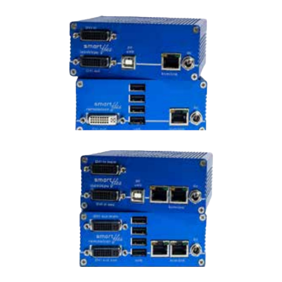
- Page 7 1. INTRODUCTION 1. INTRODUCTION 1.5 PRODUCT ELEMENTS - SMARTFLEX DUAL Local /CPU Extender Remote/CON Extender Name Function Name Function DVI out DVI to monitor DVI out sec DVi to Monitor . DVI in DVi from PC DVI out main DVi to Monitor USB to PC USB from keyboard and Maus kvm-link...
- Page 8 1. INTRODUCTION 1. INTRODUCTION 1.5 PRODUCT ELEMENTS - SMARTFLEX BACKSIDE Local /CPU Extender Name Function LED Status Display the status of the extender Reset Button for reset Name Function dvi-in second DVI connection from PC dvi-in main DVI connection to PC USB to PC kvm-link Connection for CAT5/6/7 cable...
- Page 9 1. INTRODUCTION 1. INTRODUCTION 1.6 UNPACKING AND CHECKING THE CONTENTS 1.5 ABOUT THE STATUS LED Before using the product for the first time it should be checked for damage. In case of damage due to transport inform the carrier immediately. Before delivery the product is Meaning LED displays checked for its function and its operating safety.
- Page 10 1. INTRODUCTION 2. INSTALLATION OF THE EXTENDER 1.7 MOUNTING OPTIONS 2.1 INSTALLING THE EXTENDER 1.7.1 MOUNTING PADS AND RUBBER FEET WARNING! Read and understand all safety information before installing the product. The units can be set up to access one host computer, or to access numerous host computers. The mounting pads and rubber feet can be used to hold the extenders in place and prevents In the case of the latter, an additional Network Switch must be installed.
- Page 11 2. INSTALLATION OF THE EXTENDER 2. INSTALLATION OF THE EXTENDER 2.3 QUICKINSTALLATION SMARTFLEX DUAL 2.2 QUICKINSTALLATION SMARTFLEX SINGLE 1. Power plug 1. Power plug 1. Power plug 1. Power plug 12V 1A 12V 1A 12V 1A 12V 1A 3. Network cable CAT5e/6/7/ up to 150m / 492ft main link 3.
- Page 12 2. INSTALLATION OF THE EXTENDER 2. INSTALLATION OF THE EXTENDER 2.6 BEST PRACTICE FOR WINDOWS 10 2.4 START UP Disable USB Energy Savings in Windows 10 To start up the system without switch: 1. Make sure that the two monitors and the computer are switched on. 2.
- Page 13 2. INSTALLATION OF THE EXTENDER 2. INSTALLATION OF THE EXTENDER 24 | kvm-tec kvm-tec | 25 Misprints, errors and technical changes reserved Misprints, errors and technical changes reserved...
-
Page 14: System Status
3. EXTENDER SETTINGS 3. EXTENDER SETTINGS 3. EXTENDER SETTINGS 3.1ACCESS TO THE MAIN MENU 3.2 SYSTEM STATUS Use the monitor and keyboard to access the main menu Access to the main menu (main menu): 1. Make sure the extenders, monitors and computers are turned on. 2. -
Page 15: Features Menu
3. EXTENDER SETTINGS 3. EXTENDER SETTINGS 3.4.1 POINT TO POINT 3.2 FIRMWARE VERSION DISPLAY You can switch the Point to Point mode on and off by pressing the „P“ key ATTENTION! - if the point to point mode is activated, the switching mode cannot be activated Make sure that the main menu is open. -
Page 16: Display The Last Received Image „Freeze Last Image
3. EXTENDER SETTINGS 3. EXTENDER SETTINGS 3.4.6 DIAGNOSIS MENU 3.4.4 DISPLAY THE LAST RECEIVED IMAGE „FREEZE LAST In the Diagnosis menu, the runtimes of the individual connected channels are displayed. Both IMAGE“ Remote Unit and Partner Local Unit are listed. With the function „freeze last image“... -
Page 17: Ddc Menu
3. EXTENDER SETTINGS 3. EXTENDER SETTINGS As soon as a connection to the partner has been established, the test can be started with the 3.5 DDC MENU „Enter“ key or the arrow key on the right „→“. After a valid synchronization process, the test is started and the test run time and errors are The DDC Information menu allows the user to specify which DDC information is used by the PC. -
Page 18: Ddc Main (Single Units)
3. EXTENDER SETTINGS 3. EXTENDER SETTINGS 3.5.1 DDC MAIN (SINGLE UNITS) 3.6 EXTENDER SETTINGS The Extender Settings menu allows the user to change a number of other settings. Display the Extender Settings menu: 1. Make sure that the main menu is open. 2. -
Page 19: Change The Local Settings
3. EXTENDER SETTINGS 3. EXTENDER SETTINGS 3.6.1 CHANGE THE LOCAL SETTINGS 3.6.2 USB COMPATIBILITY MODE Some PC‘s need a USB FullSpeed (USB 1.1) connection during the boot process. Our extenders are detected as USB HUB‘s - this can cause some PC‘s to abort the boot process. View the local or remote Extender settings: This can be bypassed with the USB Compatibility Mode. -
Page 20: Usb Remote Wake Up
3. EXTENDER SETTINGS 3. EXTENDER SETTINGS 3.6.4 COMPATIBILITY WITH LINUX 3.6.3. USB REMOTE WAKE UP Older Linux (before 2010) versions may not recognize the keyboard. The PC can be set into sleep mode and can be reactivated with any key. In this case please activate the Linux compatibility mode 3.6.5 BANDWIDTH REDUCTION Here the bandwidth can be reduced. -
Page 21: Vga Parameters
3. EXTENDER SETTINGS 3. EXTENDER SETTINGS 3.7 REMOTE SETTINGS 3.6.6 VGA PARAMETERS FOR MASTERFLEX AND MAXFLEX • Press the R button to display the Remote Setting menu. VGA Parameters VGA-1 Parameters 40 | kvm-tec kvm-tec | 41 Misprints, errors and technical changes reserved Misprints, errors and technical changes reserved... -
Page 22: Editing A Keyboard Layout
3. EXTENDER SETTINGS 3. EXTENDER SETTINGS 3.7.1 EDITING A KEYBOARD LAYOUT 3.7.2 KEYBOARD SHORTCUTS The Keyboard Local menu lets you switch between keyboard layouts for navigating the on With the hotkeys you can select your preferred keyboard mappings for your common screen display menu (OSD). -
Page 23: Usb Share Any Key
3. EXTENDER SETTINGS 3. EXTENDER SETTINGS 3.7.3 USB SHARE ANY KEY 3.7.4 USING THE POWER SAVING MODE By pressing the button „B“ the USB Share any Key mode can be activated or deactivated. In power save mode, the extender can turn off the video output. The delay can be set or deactivated in the Power Save Setting menu. -
Page 24: Hide Status Screen
3. EXTENDER SETTINGS 3. EXTENDER SETTINGS 3. EXTENDER SETTINGS 3.7.5 HIDE STATUS SCREEN 3.7.6 CHANGE KEYBOARD FALLBACK MODUS Press H in the Remote Settings menu. This will remove the status screen and the image remains black. To use the OSD menu, the keyboard on the remote device must be identified. For most keyboards, use the 0 setting. -
Page 25: Lock Menu
3. EXTENDER SETTINGS 3. EXTENDER SETTINGS 3.7.8 MOUSE SPEED 3.7.7 LOCK MENU Can be used in USB Emulation mode, Mouse glide & Switch. This function can be used to set the horizontal and vertical speed. This menu protects the OSD control and after 5 minutes the OSD can no longer be activated. It can be selected between 0-50 (default 30) After restarting the Remote Unit, the OSD menu is enabled again for 5 minutes. -
Page 26: Update
3. EXTENDER SETTINGS 3. EXTENDER SETTINGS 3.8 UPDATE 3.8.1 PERFORMING A FIRMWARE UPDATE VIA THE SWITCHING MANAGER The update management can be done comfortably via a Switching Manager WEB demo version. The Switching Manager WEB software can be found on the website in the support area https://www.kvm-tec.com/en/support/firmware-download/ Single In the Switching Manager WEB under the item Update ->... -
Page 27: Firmware Update With Usb Stick
3. EXTENDER SETTINGS 3. EXTENDER SETTINGS 3.8.2 FIRMWARE UPDATE WITH USB STICK For the update with an USB stick the following steps are necessary 3.9 UNLOCK AN UPGRADE 1. Make sure the main menu is open. 2. Press the U key. The Options Overview menu opens. The device ID will be shown. 3. -
Page 28: Enable Or Disable Usb Memory Upgrade
3. EXTENDER SETTINGS 3. EXTENDER SETTINGS 3.9 ENABLE OR DISABLE USB MEMORY UPGRADE The USB Memory upgrade allows the user to enable or disable the memory upgrade. When the USB Memory upgrade is enabled, USB flash storage and external storage devices can be accessed via the extender. -
Page 29: About This Device
4. NETWORK SETTINGS 3. EXTENDER SETTINGS 4. NETWORK SETTINGS AND MANAGEMENT SWITCHING SYS- 3.10 ABOUT THIS DEVICE TEMS By pressing the „A“ button, or by selecting the arrow keys, you can access the info menu, where All network settings, the user administration and the management of the extenders are done you can obtain information about hardware and software versions, as well as the activated via the included Switching Manager software and all functions are described in the Switching upgrades. -
Page 30: Push / Get List
4. NETWORK SETTINGS 4. NETWORK SETTINGS 4.2 PUSH / GET LIST 4.4 SCENARIOS Display of all extenders that can be shared. The current image of the workstation can be shared Scenarios can be defined in the Switching Manager and are selectable in the Switching List. with other remote units via this list Scenarios can also be set as favorites using the F keys. -
Page 31: Connecting, Disconnecting Or Selecting Acurrent Workplace Connected Devices
4. NETWORK SETTINGS 4.5 CONNECTING, DISCONNECTING OR SELECTING A The shortcut for favourite scenarios is CTRL+leftAlt+F1-F8. CURRENT WORKPLACE CONNECTED DEVICES ATTENTION: This is only possible if the user system is activated. The Overview display gives an overview of the currently connected PCs as well as the free PCs and consoles in the network. -
Page 32: Searchbox-Function
4. NETWORK SETTINGS 4. NETWORK SETTINGS 4.5 SEARCHBOX-FUNCTION 4.6 IP MANAGEMENT In the list view you can search for the different extenders The KVM extenders from kvm-tec support three different addressing methods. The IP Manage- ment menu is only accessible in the active “Matrix Switching Mode” under Features. Default In the List-View you can see all available extenders. - Page 33 4. NETWORK SETTINGS 4. NETWORK SETTINGS DHCP If all four IP addresses are overwritten, “Save/send settings” must be used to transmit the new values to the extenders. The KVM extenders from kvm-tec support the DHCP protocol (Dynamic Host Configuration Protocol). This allows the assignment of network addresses by a DHCP server. Static IP Static IP addresses can only be overwritten in Static IP mode.
-
Page 34: Troubleshooting & First Aid
5. TROUBLESHOOTING & FIRST AID 5. TROUBLESHOOTING & FIRST AID First smart connection MEANING OF THE LED DISPLAYS Meaning LED displays Video error (stripes Color Light display Meaning No Power USB is not working in the picture) No Video (No LED) fast flashing no active connection shining... -
Page 35: Maintance & Care
6. MAINTANCE & CARE 7. WARRANTY 7.1. STANDARD WARRANTY 6.MAINTANCE AND CARE The warranty period is 24 months from the date of purchase. (A flexible warranty extension is 6.1 EXTENDER CARE optionally available) The warranty expires in case of: Caution! Do not use solvent-containing cleaners. Do not use wipes, alcohols (e.g. spiritus) or •... -
Page 36: Cable Requirements
8. CABLE REQUIREMENTS 9. REQUIREMENTS NETWORK- SWITCH 9. REQUIREMENTS NETWORK SWITCH 8.1 REQUIREMENTS FOR CAT5E/6/7 CABLES The entire switching network system requires its own separate network. For security reasons, it A Cat5e/6/7 cable should meet the following requirements: cannot be integrated into an existing corporate network. •... -
Page 37: Contacts & Phone / Emails
Gewerbepark Mitterfeld 1A 2523 Tattendorf Austria Phone: 0043 (0) 2253 81 912 Fax: 0043 (0) 2253 81 912 99 Email: support@kvm-tec.com Web: www.kvm-tec.com IHSE China Co.,Ltd KVM-TEC KVM-TEC ASIA IHSE GmbH IHSE USA LLC IHSE GMBH Asia Room 814 Gewerbepark p +9173573 20204 Benzstr.1...
Need help?
Do you have a question about the kvm-tec FLEXLINE SMARTflex KT-6011 and is the answer not in the manual?
Questions and answers