ADTRAN NetVanta 4305 Hardware Installation Manual
Hide thumbs
Also See for NetVanta 4305:
- Hardware installation manual (56 pages) ,
- Quick start manual (2 pages) ,
- Connecting manual (2 pages)
Table of Contents
Advertisement
Quick Links
1200890L1
1200861L1
1200862L1
1200863L1
1200866L1
1200868L1
1200872L1
1200864L1
1200865L1
1200875L1
1200878L1
4202368L2
1202862L1
1202863L1
1200843L1
61200890L1-34B
July 2004
NetVanta 4305
Hardware Installation Guide
NetVanta 4305 Chassis
NetVanta 56K/64K Network Interface Module
NetVanta T1/FT1 Network Interface Module
NetVanta T1/FT1+DSX-1 Network Interface Module
NetVanta Serial Network Interface Module
NetVanta E1/FE1 Network Interface Module
NetVanta Dual T1 Network Interface Module
NetVanta Analog Modem Dial Backup Interface Module
NetVanta ISDN BRI Dial Backup Interface Module
NetVanta ISDN S/T Dial Backup Interface Module
NetVanta E1/FE1 w/ G.703 Drop Network Interface Module
Enhanced Feature Pack (VPN Upgrade)
NetVanta T1/FT1 Network Interface Module 2nd, Gen
NetVanta T1/FT1+DSX-1 Network Interface Module, 2nd Gen
NetVanta Octal T1/E1 Wide Module
Advertisement
Table of Contents

Related Manuals for ADTRAN NetVanta 4305


Summary of Contents for ADTRAN NetVanta 4305
- Page 1 NetVanta 4305 Hardware Installation Guide 1200890L1 NetVanta 4305 Chassis 1200861L1 NetVanta 56K/64K Network Interface Module 1200862L1 NetVanta T1/FT1 Network Interface Module 1200863L1 NetVanta T1/FT1+DSX-1 Network Interface Module 1200866L1 NetVanta Serial Network Interface Module 1200868L1 NetVanta E1/FE1 Network Interface Module 1200872L1...
- Page 2 To the Holder of the Manual The contents of this manual are current as of the date of publication. ADTRAN reserves the right to change the contents without prior notice. In no event will ADTRAN be liable for any special, incidental, or consequential damages or for commercial losses even if ADTRAN has been advised thereof as a result of issue of this publication.
- Page 3 NetVanta 4305 Hardware Installation Guide Conventions Conventions Notes provide additional useful information. Cautions signify information that could prevent service interruption. Warnings provide information that could prevent damage to the equipment or endangerment to human life. 61200890L1-34B © 2004 ADTRAN, Inc.
- Page 4 Safety Instructions NetVanta 4305 Hardware Installation Guide Safety Instructions When using your telephone equipment, please follow these basic safety precautions to reduce the risk of fire, electrical shock, or personal injury: 1. Do not use this product near water, such as a bathtub, wash bowl, kitchen sink, laundry tub, in a wet basement, or near a swimming pool.
- Page 5 Advance notification and the opportunity to maintain uninterrupted service are given. 4. If experiencing difficulty with this equipment, please contact ADTRAN for repair and warranty information. The telephone company may require this equipment to be disconnected from the network until the problem is corrected or it is certain the equipment is not malfunctioning.
- Page 6 FCC Radio Frequency Interference Statement NetVanta 4305 Hardware Installation Guide FCC Radio Frequency Interference Statement This equipment has been tested and found to comply with the limits for a Class A digital device, pursuant to Part 15 of the FCC Rules. These limits are designed to provide reasonable protection against harmful interference when the equipment is operated in a commercial environment.
- Page 7 NetVanta 4305 Hardware Installation Guide Industry Canada Compliance Information Industry Canada Compliance Information Notice: The Industry Canada label applied to the product (identified by the Industry Canada logo or the “IC:” in front of the certification/registration number) signifies that the Industry Canada technical specifications were met.
- Page 8 Affidavits NetVanta 4305 Hardware Installation Guide Affidavits Affidavit Requirements for Connection to Digital Services • An affidavit is required to be given to the telephone company whenever digital terminal equipment without encoded analog content and billing protection is used to transmit digital signals containing encoded analog content which are intended for eventual conversion into voiceband analog signals and transmitted on the network.
- Page 9 NetVanta 4305 Hardware Installation Guide Affidavits Affidavit for Connection Of Customer Premises Equipment to 1.544 Mbps And/or Subrate Digital Services For the work to be performed in the certified territory of ___________________(telco name) State of ________________ County of ________________ I, _______________________ (name), _____________________________(business address), ____________________ (telephone number) being duly sworn, state: I have responsibility for the operation and maintenance of the terminal equipment to be connected to 1.544 Mbps and/or ________ subrate...
- Page 10 NetVanta 4305 Hardware Installation Guide Warranty and Customer Service ADTRAN will repair and return this product within the warranty period if it does not meet its published specifications or fails while in service. Warranty information can be found at: http://support.adtran.com (Click on Warranty and Repair Information, under Support.)
- Page 11 Your reseller should serve as the first point of contact for support. If additional pre-sales support is needed, the ADTRAN Support web site provides a variety of support services such as a searchable knowledge base, latest product documentation, application briefs, case studies, and a link to submit a question to an Applications Engineer.
- Page 12 These courses include overviews on product features and functions while covering applications of ADTRAN's product lines. ADTRAN provides a variety of training options, including customized training and courses taught at our facilities or at your site. For more information about training, please contact your Territory Manager or the Enterprise Training Coordinator.
-
Page 13: Table Of Contents
Contents of ADTRAN Shipments ........ - Page 14 Table of Contents NetVanta 4305 Hardware Installation Guide © 2004 ADTRAN, Inc. 61200890L1-34B...
- Page 15 NetVanta 4305 Front Panel Layout ........
- Page 16 List of Figures NetVanta 4305 Hardware Installation Guide © 2004 ADTRAN, Inc. 61200890L1-34B...
- Page 17 10/100BaseT Ethernet Port Pinouts ......... . 45 Table A-2. Console Port (DCE) Pinout for NetVanta 4305 (p/n 1200890L1) ....45 Table A-3.
- Page 18 List of Tables NetVanta 4305 Hardware Installation Guide © 2004 ADTRAN, Inc. 61200890L1-34B...
-
Page 19: Introduction To The Netvanta 4305
INTRODUCTION TO THE NETVANTA 4305 The NetVanta 4305 is a mid-range IP router designed for medium-to-large office connectivity over Frame Relay or point-to-point (PPP) networks. This modular platform offers a complete solution for access routing and WAN connectivity in a single, compact package. -
Page 20: Unpack And Inspect The System
AOS Command Reference Guide, also on the CD. Unpack and Inspect the System Each NetVanta 4305 unit is shipped in its own cardboard shipping carton. Open each carton carefully, and avoid deep penetration into the carton with sharp objects. - Page 21 Shipments of the T1/E1 NIM include the following items: • Two T1/E1 Network Interfaces • Quick Start Guide • Two 15-foot RJ-45 to RJ-45 cable (ADTRAN P/N 3125M008@A) NetVanta Serial NIM (1200866L1) Shipments of the Serial NIM include the following items: • Serial Network Interface Module •...
- Page 22 Introduction to the NetVanta 4305 NetVanta 4305 Hardware Installation Guide • RJ-45 to RJ-11 cable (ADTRAN P/N 3125M007@A) NetVanta ISDN S/T DIM (1200875L1) Shipments of the ISDN S/T DIM include the following items: • ISDN S/T Dial Backup Interface Module •...
-
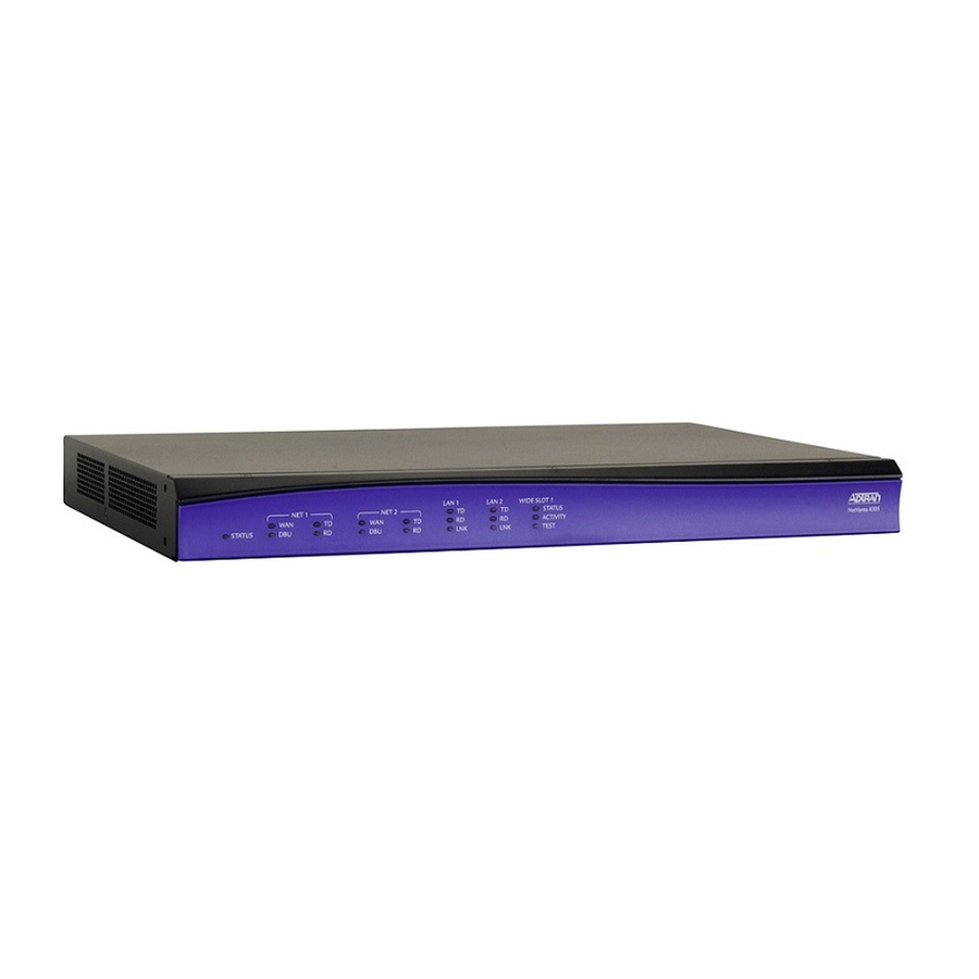
Page 23: Physical Description
NetVanta 4305 Hardware Installation Guide Physical Description PHYSICAL DESCRIPTION Reviewing the Base Unit Front Panel Design Figure 1 shows the NetVanta 4305 front panel. LAN 1 LAN 2 WIDE SLOT 1 NET 1 NET 2 STATUS ACTIVITY STATUS TEST NetVanta 4305 Figure 1. - Page 24 Physical Description NetVanta 4305 Hardware Installation Guide Table 1. NetVanta 4305 LEDs (Continued) For these This activity… Indicates that… LEDs… LAN 1/ LAN 2 Green (solid) The 10BaseT Ethernet link is up. Yellow (solid) The 100BaseT Ethernet link is up.
-
Page 25: Reviewing The Rear Panel Design
NetVanta 4305 Hardware Installation Guide Physical Description Reviewing the Rear Panel Design Figure 2 shows the rear panel for the NetVanta 4305. The chassis is shown with the T1/FT1+DSX-1 NIM installed. ETH 0/2 100-250VAC 50/60Hz WAN-T1 DSX-1 WAN-T1 DSX-1 WAN-T1... -
Page 26: Option Modules
NetVanta 4305 Hardware Installation Guide OPTION MODULES The NetVanta 4305 accepts several option modules designed to meet a variety of networking requirements. The option modules are of three types: plug-in Network Interface Modules (NIMs), plug-on Dial Backup Interface Modules (DIMs), and Wide NIMs. -
Page 27: Network Interface Modules
NetVanta 56K/64K NIM (P/N 1200861L1) The 56K/64K NIM (shown in Figure 3) provides a interface for the NetVanta 4305. Refer to WAN-DDS Table A-3 on page 46 for the WAN-DDS connector pinout, and refer to Table A-9 on page 49 for the DBU connector pinout. -
Page 28: Netvanta T1/Ft1 Nim (P/N 1200862L1 Or P/N 1202862L1)
The T1/FT1 NIM (shown in Figure 4) provides a T1 (full T1 or fractional T1) WAN interface for the NetVanta 4305. Refer to Table A-4 on page 46 for the WAN-T1 connector pinout, and refer to Table A-9 on page 49 for the DBU connector pinout. An optional DIM is required for dial backup applications. -
Page 29: Netvanta T1/Ft1+Dsx-1 Nim (P/N 1200863L1 Or P/N 1202863L1)
NetVanta 4305 Hardware Installation Guide Option Modules NetVanta T1/FT1+DSX-1 NIM (P/N 1200863L1 or P/N 1202863L1) The T1/FT1 + DSX-1 NIM (see Figure 5) provides a full T1 or fractional T1 network interface and a DSX- 1 interface. Refer to Table A-4 on page 46 for the WAN-T1 connector pinout, Table A-6 on page 47 for the DSX-1 connector pinout, and Table A-9 on page 49 for the DBU connector pinout. -
Page 30: Netvanta Dual T1 Nim (P/N 1200872L1)
NetVanta Dual T1 NIM (P/N 1200872L1) The NetVanta Dual T1 NIM (see Figure 6) provides two WAN T1 interfaces for the NetVanta 4305. The module provides up to 2.048 Mbps on each network interface. Refer to Table A-5 on page 46 for the pinouts. -
Page 31: Netvanta Serial Nim (P/N 1200866L1)
The NetVanta Serial NIM (shown in Figure 7) is user-configurable to be either a V.35 or X.21 (V.11) interface. This module supports rates up to a maximum of 10 Mbps. An additional V.35 (ADTRAN P/N 1200873L1) or X.21 (ADTRAN P/N 1200874L1) cable is required (see Caution, below). Refer to Table A-8 on page 48 for the Serial connector pinout, and refer to Table A-10 on page 49 for the DBU connector pinout. -
Page 32: Netvanta E1/Fe1 Nim (P/N 1200868L1)
NetVanta 4305 Hardware Installation Guide NetVanta E1/FE1 NIM (P/N 1200868L1) The NetVanta E1 NIM (see Figure 8) provides a interface for the NetVanta 4305 meeting the WAN-E1 requirements of ITU-T G.703/G.704. The module provides a single 2.048 Mbps network interface. Refer to Table A-5 on page 46 for the pinouts. -
Page 33: Netvanta E1/Fe1 With G.703 Drop Nim (P/N 1200878L1)
NetVanta 4305 Hardware Installation Guide Option Modules NetVanta E1/FE1 with G.703 Drop NIM (P/N 1200878L1) The NetVanta E1/FE1 with G.703 Drop NIM (see Figure 9) provides a single interface WAN-E1 (2.043 Mbps) with user-selectable TS0 assignment and a G.703 drop port which may be used to drop and insert traffic to an E1 PBX. -
Page 34: Netvanta Octal T1 Wide Nim (P/N 1200843L1)
Option Modules NetVanta 4305 Hardware Installation Guide NetVanta Octal T1 Wide NIM (P/N 1200843L1) The NetVanta Octal T1 Wide NIM (shown in Figure 10) provides eight T1 (full T1 or fractional T1) WAN interfaces. Refer to Table A-4 on page 46 for the T1 interface pinout. -
Page 35: Dial Backup Interface Modules
NetVanta Analog Modem DIM (P/N 1200864L1) The Analog Modem DIM provides a modem with data rates up to 33.6 kbps for the NetVanta 4305. This DIM is a plug-on card that connects to the NIM. For installation instructions, see Installing Dial Backup and Network Interface Modules on page 41. -
Page 36: Netvanta Isdn Bri Dim (P/N 1200865L1)
The NetVanta ISDN BRI DIM provides dial backup access to the public switched telephone network (PSTN) via Basic Rate ISDN for the NetVanta 4305. This DIM is a plug-on module that connects to the NIM. For installation instructions, see Installing Dial Backup and Network Interface Modules on page 41. -
Page 37: Netvanta Isdn S/T Dim (P/N 1200875L1)
The NetVanta ISDN S/T DIM provides dial backup access to the public switched telephone network (PSTN) via Basic Rate ISDN for the NetVanta 4305. This DIM is a plug-on module that connects to the NIM. For installation instructions, see Installing Dial Backup and Network Interface Modules on page 41. -
Page 38: Unit Installation
For information on router configuration for a specific application, refer to the quick start documents provided on your ADTRAN OS Documentation CD. For details on the command line interface, refer to the AOS Command Reference Guide (also included on your CD). -
Page 39: Mounting Options
Decide on a location for the NetVanta 4305. Keep in mind that the unit needs to be mounted at or below eye-level so that the LEDs are viewable. Important! Mount the chassis with LEDs facing to the side (not facing up or down). -
Page 40: Supplying Power To The Unit
Supplying Power to the Unit As shipped, each NetVanta 4305 is set to factory default conditions. After installing the base unit and any option modules, the NetVanta 4305 is ready for power-up. To power-up the unit, ensure that the unit is properly connected to an appropriate power source (as outlined in the sections below). -
Page 41: Installing Dial Backup And Network Interface Modules
NetVanta 4305 Hardware Installation Guide Unit Installation Installing Dial Backup and Network Interface Modules The DIMs plug on to the NIMs. The NIMs are then installed in the rear panel option module slot. The following tables list the installation steps. See Figure 11 below and Figure 12 on page 42. -
Page 42: Figure 12. Nim And Dim Installation
Figure 12. NIM and DIM Installation Your NetVanta 4305 is now ready to be configured and connected to the network. For more information on configuration for a specific application, refer to the quick start documents provided on your ADTRAN OS Documentation CD. -
Page 43: Installing The Netvanta Vpn Accelerator Card (1202368L1)
The optional VPN Accelerator Card plugs into a 32-bit PCI slot and is designed to be used in the NetVanta 4305 to provide encryption/decryption and security acceleration services. The card provides the following security services to the host processor: DES, Triple-DES, AES, SHA-1, MD5, and Random Number Generation. - Page 44 Unit Installation NetVanta 4305 Hardware Installation Guide © 2004 ADTRAN, Inc. 61200890L1-34B...
-
Page 45: Appendix A. Connector Pin Definitions
Transmit Positive Transmit Negative Receive Positive — Unused Receive Negative — Unused Table A-2. Console Port (DCE) Pinout for NetVanta 4305 (p/n 1200890L1) Name Description Data Carrier Detect (output) Receive Data (output) Transmit Data (input) Data Terminal Ready (input) Signal Ground Data Set Ready Tied to pin 1 (output) —... -
Page 46: Table A-3. Wan-Dds Connector Pinouts
Appendix A. Connector Pin Definitions NetVanta 4305 Hardware Installation Guide Network Interface Module (NIM) and Wide NIM Pinouts Table A-3. WAN-DDS Connector Pinouts Name Description Transmit data to the network—Ring 1 Transmit data to the network—Tip 1 — Unused Receive data from the network—Tip Receive data from the network—Ring... -
Page 47: Table A-6. Dsx-1 Connector Pinout
NetVanta 4305 Hardware Installation Guide Appendix A. Connector Pin Definitions Table A-6. DSX-1 Connector Pinout Name Description Transmit data toward the DTE—Ring Transmit data toward the DTE—Tip — Unused Receive data from the DTE—Ring 1 Receive data from the DTE—Tip 1 —... -
Page 48: Table A-8. Serial Nim Connector Pinouts
Appendix A. Connector Pin Definitions NetVanta 4305 Hardware Installation Guide Table A-8. Serial NIM Connector Pinouts Name Name TD_A TD_B ETC_A ETC_B TCLK_A TCLK_B RCLK_A RCLK_B RD_A RD_B DCD_A Unused DTR_A Unused RTS_A Unused RTS_B (V.11 only) Unused CTS_B (V.11 only) -
Page 49: Table A-9. Dbu Connector Pinouts
NetVanta 4305 Hardware Installation Guide Appendix A. Connector Pin Definitions Dial Backup (DBU) Connectors Table A-9 describes the pinouts for the following modules: 56/64K, T1/FT1 (1st generation), and T1/ FT1+DSX-1 (1st generation). Table A-9. DBU Connector Pinouts Name Description Network–Ring 1 Network—Tip 1... - Page 50 Appendix A. Connector Pin Definitions NetVanta 4305 Hardware Installation Guide © 2004 ADTRAN, Inc. 61200890L1-34B...
- Page 51 20 DSX-1 interface pinout 47 dual T1/E1 interface 19 E1/FE1 interface 19 E1/FE1 w/ G.703 drop interface 19 features of the NetVanta 4305 19 Frame Relay 19 front panel 23 G.703 interface pinout 47 installing NetVanta unit 38 installing the accelerator card 43...
- Page 52 NetVanta 4305 Hardware Installation Guide LEDs 23 front panel 23 mounting options rack 39 wall 39 NET 1/NET 2 DBU LED 23 NET 1/NET 2 TD/RD LED 23 NET 1/NET 2 WAN LED 23 NetVanta 4305 features and specifications 19...
- Page 53 NetVanta 4305 Hardware Installation Guide option modules 26 pinouts 10/100BaseT Ethernet 45 console port 45 DBU 23, 49 DSX-1 47 G.703 47 serial 48 WAN-DDS 46 WAN-E1 46 WAN-T1 46 power 40 NetVanta 4305 (AC) 40 PPP 19 product registration 10...
Need help?
Do you have a question about the NetVanta 4305 and is the answer not in the manual?
Questions and answers