Advertisement
Available languages
Available languages
Quick Links
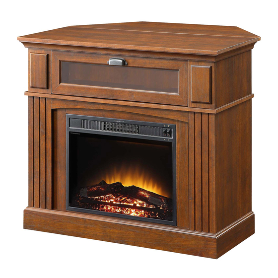
Sumner Corner Media Fireplace
If you have any questions regarding assembly or if parts are missing, DO NOT return this item to the
store where it was purchased. Please call our customer service number and have your instructions
and parts list ready to provide the model name, part name or factory number:
Pacific Standard Time: 8:30 a.m. - 4:30 p.m., Monday - Friday
Or visit our web site 24 hours a day, 7 days a week for product assistance at
THIS INSTRUCTION BOOKLET CONTAINS IMPORTANT SAFETY INFORMATION.
Stock # SUMCMF-23
ADULT ASSEMBLY REQUIRED
www.whalenstyle.com
Or e-mail your request to parts@whalenfurniture.com
PLEASE READ AND KEEP FOR FUTURE REFERENCE.
Date 2019-07-02
# SUMCMF-23B
866-942-5362
Rev. 0001-C
LOT NUMBER:
DATE PURCHASED:
/
/
Advertisement

Related Manuals for Whalen Sumner Corner SUMCMF-23


Summary of Contents for Whalen Sumner Corner SUMCMF-23
- Page 1 LOT NUMBER: DATE PURCHASED: Sumner Corner Media Fireplace Stock # SUMCMF-23 # SUMCMF-23B ADULT ASSEMBLY REQUIRED If you have any questions regarding assembly or if parts are missing, DO NOT return this item to the store where it was purchased. Please call our customer service number and have your instructions and parts list ready to provide the model name, part name or factory number: 866-942-5362 Pacific Standard Time: 8:30 a.m.
-
Page 2: Quality Guarantee
Should this product be defective in workmanship or materials or fail under normal use, we will repair or replace it for up to one (1) year from date of purchase. Every Whalen Furniture product is designed to meet your highest expectations. We guarantee that you will immediately see the value of our fine furniture. - Page 3 IMPORTANT Before you begin: Open, identify and count all parts prior to assembly. Lay out parts on a flat and non- abrasive surface. You will need the parts identified on page 4 and 5 of this instruction manuals. NOTE: IT IS VERY IMPORTANT TO USE GLUE WITH DOWELS. EXCESS GLUE CAN BE WIPED OFF WITH DAMP CLOTH.
- Page 4 Parts and Hardware List Please read completely through the instructions and verify that all listed parts and hardware are present before beginning assembly. A- Top Panel (1) B- Center Shelf (1) C- Bottom Panel (1) D- Front Bottom Molding (1) E- Back Bottom Stretcher (1) F- Left Lower Side Panel (1) G- Left Lower Front Panel (1)
- Page 5 Parts and Hardware List Please read completely through the instructions and verify that all listed parts and hardware are present before beginning assembly. S- Stop Rail (1) Fireplace Insert (1) (1) Cam Lock (2) Cam Bolt (3) M8 x 30 mm Wood Dowel (4) M8 x 20 mm Wood Dowel (42+2 extra) (42+2 extra)
- Page 6 Assembly Instructions Cam Bolt (22 used in this step) ② 1. Unpack the unit and confirm that you have all the hardware and required parts listed. Assemble the unit on a carpeted floor or the empty carton to avoid any scratch. 2.
- Page 7 Assembly Instructions Cam Bolt (10 used in this step) ② 3. Secure screw the Cam Bolts (2) into the designated small holes on the Left and Right Front Panels (G and I) and Lower Side Panels (F and H), as shown in the illustration.
- Page 8 Assembly Instructions Cam Lock (4 used in this step) ① M8 x 30 mm Wood Dowel (4 used in this step) ③ 4. Insert two M8 x 30 mm Wood Dowels (3) into the inner holes of the Left Lower Side Panel (F). Tap in with a rubber mallet, if necessary.
- Page 9 Assembly Instructions Cam Lock M8 x 30 mm Wood Dowel (2 used in this step) (2 used in this step) ① ③ 7. Align and attach the Center Front Molding (J) to the Center Shelf (B) by using two M8 x 30 mm Wood Dowels (3) and two Cam Locks (1).
- Page 10 Assembly Instructions M8 x 30 mm Wood Dowel Cam Lock (4 used in this step) (6 used in this step) ① ③ 8. Align and attach the Back Bottom Stretcher (E) to the Bottom Panel (C) by using two M8 x 30 mm Wood Dowels (3) and three Cam Locks (1).
- Page 11 Assembly Instructions Cam Lock M8 x 30 mm Wood Dowel (6 used in this step) (6 used in this step) ① ③ 10. Glue six M8 x 30 mm Wood Dowels (3) into the drilled holes of the assembled base at both ends. DO NOT insert the wood dowels into the cam bolt holes.
- Page 12 Assembly Instructions #8 x 1-1/2” Wood Screw (4 used in this step) ⑤ 13. Insert four 1-1/2” Wood Screws (5) through the drilled holes on the Bottom Panel (C) and securely screw into the Front Panels (G and I) by a Phillips screwdriver, as shown above.
- Page 13 Assembly Instructions Angle Metal Bracket 5/8” Flat Head Screw (2 used in this step) (8 used in this step) ⑦ 14. With the pilot holes as a guide, align and attach two Angle Metal Brackets (12) to the front corners of the assembled base, using four 5/8”...
- Page 14 Assembly Instructions Floor Leveler (2 used in this step) 15. Screw two Floor Levelers (13) into the threaded sockets on the Angle Metal Brackets (12).
- Page 15 Assembly Instructions Cam Lock M8 x 30 mm Wood Dowel (8 used in this step) (6 used in this step) ③ ① 16. Stand the previous assembly upright. 17. Insert six M8 x 30 mm Wood Dowels (3) into the inner holes on the top of the assembled unit. 18.
- Page 16 Assembly Instructions 5/8” Flat Head Screw (4 used in this step) ⑦ Straight Metal Bracket (2 used in this step) 19. With the pilot holes as a guide, fasten the Center Front Molding (J) to the Front Panels (G and I) by attaching two Metal Brackets (11) at the joints, using two 5/8”...
- Page 17 Assembly Instructions Cam Bolt (6 used in this step) ② 20. Securely screw six Cam Bolts (2) into the designated small holes on the Center Shelf (B). As shown above.
- Page 18 Assembly Instructions Cam Lock (4 used in this step) ① Cam Bolt (4 used in this step) ② M8 x 30 mm Wood Dowel (2 used in this step) ③ 21. Securely screw two Cam Bolts (2) into the designated small holes on one Upper Front Panel (R), as shown. 22.
- Page 19 Assembly Instructions M8 x 30 mm Wood Dowel Cam Lock (6 used in this step) (6 used in this step) ③ ① 24. Glue six M8 x 30 mm Wood Dowels (3) into the drilled holes on the Center Shelf (B). Fasten the Upper Side Panel assemblies onto the Center Shelf (B) by engaging six Cam Locks (1).
- Page 20 Assembly Instructions Cam Lock M8 x 30 mm Wood Dowel (6 used in this step) (6 used in this step) ① ③ 25. Align and attach the Top Panel (A) onto the assembled Upper Support Panels (K and R) with six Wood Dowels (3) and six Cam Locks (1).
- Page 21 Assembly Instructions 5/8” Washer Head Screw (16 used in this step) ⑧ 26. Now, go back and securely tighten all the Cam Locks and screws. Make sure that all the parts are tight and there are no gaps between the pieces. This will help keep the unit square. 27.
- Page 22 Assembly Instructions 28. Unpack the fireplace insert from the inner box and follow the instructions to install the Top Trim and Side Trims to the fireplace insert. 29. Lift the fireplace insert carefully into the back of the assembled mantel and center it in the opening. drag the insert across the Bottom Panel (C) as it may scratch the unit.
- Page 23 Assembly Instructions 2” Lag Bolt (4 used in this step) ⑩ 30. Align and attach two Firebox Supports (Q) to the Bottom Panel (C) by inserting the 2” Lag Bolts (10) into the countersunk holes of the Firebox Supports and securely screw into place. As shown above. NOTE: If you choose the Wall Mantel configuration, please skip to page 28.
- Page 24 Assembly Instructions 1/2” Bolt (2 used in this step) ⑨ #8 x 3/4” Screw M8 x 20 mm Wood Dowel Plastic Connector (3 used in this step) (2 used in this step) (2 used in this step) ⑥ ④ 31. Glue two M8 x 20 mm Wood Dowels (4) as a guide, combine the Corner Short Support (P) and Long Support (O) together by inserting three 3/4”...
- Page 25 Assembly Instructions 1/2” Bolt Plastic Connector (3 used in this step) (3 used in this step) ⑨ 33. Align and fasten three Plastic Connectors (14) to the Top Corner Extension (N) with the 1/2” Bolts (9). As shown above.
- Page 26 Assembly Instructions 1/2” Bolt (1 used in this step) ⑨ 34. Align and attach the Corner Long Support (O) to the Top Corner Extension (N) by inserting one 1/2” Bolt (9) throuth the Plastic Connector (14) and screw into the threaded insert on the Top Corner Extension.
- Page 27 Assembly Instructions 1/2” Bolt M8 x 30 mm Wood Dowel (4 used in this step) (4 used in this step) ③ ⑨ 35. Glue four M8 x 30 mm Wood Dowels (3) into the drilled holes on the back edge of the Top Panel (A) as a guide.
- Page 28 Assembly Instructions Door Pull 5/8” Small Bolt (1 used in this step) (2 used in this step) 36. Attach the Door Pull (15) to the front side of the Door (L) with the provided 5/8” Small Bolts (16). 37. Align and insert the bottom plastic pins of the Door (L) into the plastic bushings on the Center Shelf (B) and snap the upper spring balls into place.
- Page 29 Assembly Instructions NOTE: You must install the Strip Stopper to prevent the TV from tipping when placing your flat panel television directly on the Top Panel. 38. Remove the paper backing from the Stop Rail (S), then properly align the Stop Rail with the top edge of the stopper template on Top Panel (A).
- Page 30 Assembly Instructions Tools required: Phillips screwdriver, power drill, 3/8” drill bit and rubber mallet. 40. Ask for assistance to position the assembled mantel at the desired location against a wall. If necessary, adjust the Floor Levelers (13) under the Mantel Base to level the unit. 41.
-
Page 31: Care And Maintenance
Care and Maintenance Use a soft, clean cloth that will not scratch the surface when dusting. Use of furniture polishes is not necessary. Should you choose to use polishes, test first in an inconspicuous area. Using solvents of any kind on your furniture may damage the finish. ... - Page 33 LOTE NUMERO: FECHA DE COMPRA Chimenea esquina y multimedia Sumner Serie # SUMCMF-23 # SUMCMF-23B ENSAMBLE REQUERIDO POR ADULTO Si tienen alguna pregunta acerca del ensamble o si alguna parte está faltante, no retorne esté producto a la tienda que lo compro. Por favor llame a nuestro departamento de ayuda al cliente teniendo su instructivo y lista de partes para proveer el modelo, nombre de parte o el número de fábrica: 1-866-942-5362 Hora del Pacífico: 8:30 a.m.
- Page 34 Todo producto de Whalen Furniture es diseñado para alcanzar sus espectativas más altas. Nosotros le garantizamos que inmediatamente podrá ver el valor de nuestra mercancia de la más alta calidad. Está garantia le proporciona...
- Page 35 IMPORTANTE Antes de comenzar: Abra, identifique y cuente todas las partes antes del ensamble. Coloque las piezas sobre una superficie plana y no abrasiva. Tendrá que las partes identificadas en la página 4 y 5 de este manual de instrucciones. NOTA ES MUY IMPORTANTE PARA EL USO DE GOMA CON LOS PERNSO DE MADERA.
- Page 36 Lista de partes y artículos de ferretería Por favor lea completamente las instrucciones y verifique que estén todas las partes y artículos de ferretería antes de iniciar el ensamble A- Panel superior (1) B- Repisa central (1) C- Panel inferior (1) D- Moldura inferior frontal (1) E- Soporte inferior posterior (1) F- Panel Lat.
- Page 37 Lista de partes y artículos de ferretería Por favor lea completamente las instrucciones y verifique que estén todas las partes y artículos de ferretería antes de iniciar el ensamble S- Riel tope (1) Inserto chimenea (1) (1) Tuerca de fijación (2) Tornillo de fijación (3) Perno madera M8 x 30 mm (4) Perno madera M8 x 20 mm (42+2 extra) (42+2 extra) (40+2 extra)
-
Page 38: Instrucciones De Ensamble
Instrucciones de ensamble Tornillo de fijación (22 usados es este paso) ② 1. Desempacar la unidad y asegurese de que usted tiene todo el herraje y las piezas necesarias en la lista. Ensamble la unidad en un lugar o de la caja de cartón vacía para evitar cualquier rasguño. 2. - Page 39 Instrucciones de ensamble Tornillo de fijación (10 usados es este paso) ② Fijar los tronillos de fijación (2) en los orificios pequeños designados en los paneles delanteros izquierdo y derecho (G e I) e inferior paneles laterales (F y H), como se muestra en la ilustración.
- Page 40 Instrucciones de ensamble Tuerca de fijación (4 usados es este paso) ① Perno de madera M8 x 30 mm (4 usados en este paso) ③ 4. Inserte dos pernos de madera M8 x 30 mm (3) en los agujeros internos de la parte baja del panel lateral izquierdo (F).
- Page 41 Instrucciones de ensamble Tuerca de Fijación Perno de madera M8 x 30 mm (2 usados en este paso) (2 usados en este paso) ① ③ 7. Alinear y colocar la moldura frontal central (J) en la repisa central (B) mediante el uso de dos pernos de madera M8 x 30 mm (3) y dos tuercas de fijación (1).
- Page 42 Instrucciones de ensamble Perno de madera M8 x 30 mm Tuerca de fijación (4 usados en este paso) (6 usados en este paso) ① ③ 8. Alinee y coloque el soporte inferior posterior (E) al panel inferior (C) utilizando dos pernos de madera M8 x 30 mm (3) y tres tuercas de fijación (1).
- Page 43 Instrucciones de ensamble Tuerca de fijación Tornillo de M8 x 30 mm (6 usados en este paso) (6 usados en este paso) ① ③ 10. Pegar seis pernos de madera M8 x 30 mm (3) en los agujeros perforados de la base montada en ambos extremos.
- Page 44 Instrucciones de ensamble Tornillo para madera de #8 x 1-1/2” (4 usados en este paso) ⑤ 13. Insertar cuatro tornillos para madera de 1-1/2” (5) atravez de los agujeros del panel inferior (C) y asegurar en el panel frontal (G y I) con un destornillador estrella, como se muestra arriba.
- Page 45 Instrucciones de ensamble Soporte de metal Tornillo de 5/8” cabeza plana angular (8 usados en este paso) (2 usados en este paso) ⑦ 14. Con los agujeros piloto como guía, alinear y fijar dos soportes de metal (12) a las esquinas frontales angular de la base ensamblada, usando cuatro tornillos de cabeza plana de 5/8”...
- Page 46 Instrucciones de ensamble Nivelador de piso (2 usados en este paso) 15. Fijar dos niveladores de piso (13) en los insertos roscados de los soportes de metal angular (12).
- Page 47 Instrucciones de ensamble Tuerca de fijación Perno de madera M8 x 30 mm (6 usados en este paso) (8 usados en este paso) ③ ① 16. Poner la unidad en forma vertical. 17. Pegar seis pernos de madera de M8 x 30 mm (3) en los agujeros internos en la tapa de la unidad ensamblada.
- Page 48 Instrucciones de ensamble Tornillo de 5/8” cabeza plana (4 usados en este paso) ⑦ Soporte de metal recto (2 usados en este paso) 19. Con los agujeros piloto como guía, fijar la moldura central frontal (J) a los paneles frontales (G y I) con dos soportes de metal (11) en las uniones, usando dos tornillos de 5/8”...
- Page 49 Instrucciones de ensamble Tornillo de fijación (6 usados en este paso) ② 20. Fijar completamente seis tornillos de fijación (2) en los agujeros designados de la repisa central (B). Como se muestra arriba.
- Page 50 Instrucciones de ensamble Tuerca de fijación (4 usados en este paso) ① Tornillo de fijación (4 usados en este paso) ② Perno de madera M8 x 30 mm (2 usados en este paso) ③ 21. Fijar tornillos de fijación (2) en los orificios pequeños designados en el panel frontal superior (R), como se muestra.
- Page 51 Instrucciones de ensamble Perno de madera M8 x 30 mm Tuerca de fijación (6 usados en este paso) (6 usados en este paso) ③ ① 24. Pegar seis pernos de madera M8 x 30 mm (3) en los agujeros de la repisa central (B). Fijar el panel superior a la repisa central (B) con seis tuercas de fijación (1).
- Page 52 Instrucciones de ensamble Perno de madera M8 x 30 mm Tuerca de fijación (6 usados en este paso) (6 usados en este paso) ① ③ 25. Alinear y fijar el panel superior (A) al ensamble del soporte superior (K y R) con seis pernos de madera (3) y seis tuercas de fijación (1).
- Page 53 Instrucciones de ensamble Tornillo cabeza especial de 5/8” (16 usados en este paso) ⑧ 26. Ahora, regrese y apriete firmemente todos los seguros y los tornillos. Asegúrese de que todas las piezas estén apretadas y que no haya espacios entre las piezas. Esto ayudará a mantener escuadra la unidad. 27.
- Page 54 Instrucciones de ensamble 28. Desempaque la chimenea de la caja interior y siga las instrucciones para instalar la moldura superior y lateral a la chimenea. 29. Levante la chimenea con cuidado en la parte posterior de la repisa de la chimenea montada y centrarlo en la apertura.
- Page 55 Instrucciones de ensamble Tornillo de 2” (4 usados en este paso) ⑩ 30. Alinear y colocar dos soportes de chimenea (Q) al panel inferior (C) insertando los tornillos de 2" (10) en los agujeros avellanados del soporte de chimenea y el tornillo en su lugar de forma segura. Como se muestra más arriba.
- Page 56 Instrucciones de ensamble Tornillo de 1/2” (2 usados en este paso) ⑨ Perno de madera M8 x 20 mm Tornillo #8 x 3/4” Conector plástico (2 usados en este paso) (3 usados en este paso) (2 usados en este paso) ⑥...
- Page 57 Instrucciones de ensamble Tornillo de 1/2” Conector plástico (3 usados en este paso) (3 usados en este paso) ⑨ 33. Alinear y fijar 3 conectores plásticos (14) a la extención de tapa (N) con los tornillos de 1/2” (9). Como se muestra arriba.
- Page 58 Instrucciones de ensamble Tornillo de 1/2” (1 usado en este paso) ⑨ 34. Alinear y fijar los soportes esquina largos (O) a la extención de tapa (N) con un tornillo de 1/2” (9) atravez del conector de plástico (14) y asegurar hacia los insertos roscados en la extención de tapa.
- Page 59 Instrucciones de ensamble Tornillo de 1/2” Perno madera M8 x 30 mm (4 usados en este paso) (4 usados en este paso) ③ ⑨ 35. Pegar cuatro pernos de madera M8 x 30 mm (3) en los agujeros perforados en el borde posterior del panel superior (A) como guía.
- Page 60 Instrucciones de ensamble Jaladera Tornillo corto 5/8” (1 usado en este paso) (2 usados en este paso) 36. Fijar la jaladera (15) a la parte frontal de la puerta (L) con los tornillos cortos de 5/8” (16) proveidos. 37. Alinear e insertar los pernos de plástico de la puerta (L) en los insertos de plástico de la repisa central (B) y colocar los baleros superiores con resorte en su lugar.
- Page 61 Instrucciones de ensamble NOTA: Es necesario instalar el tapón para evitar que el televisor se caiga al poner su televisor de pantalla plana directamente en el panel superior. 38. Retire el papel protector del riel tope (S), y luego alinear correctamente el riel tope con el borde superior de la plantilla en el panel superior (A).
- Page 62 Instrucciones de ensamble Herramienta requerida: Destornillador de estrella, taladro, broca de 3/8” y mazo de goma. 40. Pida ayuda para colocar la chimenea cerca de la pared in la locación deseada. Si es necesario ajustar los niveladores de piso (13) que estan localizados debajo de la chimenea para nivelar la unidad. 41.
-
Page 63: Mantenimiento Y Cuidados
Mantenimiento y cuidados Use una toalla suave y limpia para evitar daños y rayaduras. Uso de cera para pulir muebles no es necesario. Si desea usar cera cheque en una area que no sea visible para checar su funcionamiento. ...
Need help?
Do you have a question about the Sumner Corner SUMCMF-23 and is the answer not in the manual?
Questions and answers