Advertisement
Available languages
Available languages
REPLACEMENT PARTS LIST
For replacement parts, call our customer service department at 1-866-942-5362,
8:30 a.m. - 4:30 p.m., PST, Monday - Friday.
PART
DESCRIPTION
A
Top Panel
B
Bottom Panel
C
Center Shelf
D
Left Side Frame
E
Right Side Frame
F
Left Partition Panel
G
Right Partition Panel
H
Upper Partition Panel
I
Bottom Back Stretcher
J
Bottom Front Stretcher
K
Bottom Front Molding
L
Middle Crossbar
M
Adjustable Shelf
N
Left Door
O
Right Door
P
Door Glass
Q
Upper Back Panel
R
Lower Back Panel
S
Wood Door Panel
Door Hinge with Screws
Complete Hardware
Complete Fireplace Inert
Remote Control 6-Buttom
A
R
D
M
F
S
N
PART#
*WSLWFP54-6-01-TP
*WSLWFP54-6-02-BP
*WSLWFP54-6-03-CS
*WSLWFP54-6-04-LSF
*WSLWFP54-6-05-RSF
*WSLWFP54-6-06-LPP
*WSLWFP54-6-07-RPP
*WSLWFP54-6-08-UPP
*WSLWFP54-6-09-BBS
*WSLWFP54-6-10-BFS
*WSLWFP54-6-11-BFM
*WSLWFP54-6-12-MC
*WSLWFP54-6-13-AS
*WSLWFP54-6-14-LD
*WSLWFP54-6-15-RD
*WSLWFP54-6-16-DG
*WSLWFP54-6-17-UBP
*WSLWFP54-6-18-LBP
*WSLWFP54-6-19-WDP
*WSLWFP54-6-20-DHS
*WSLWFP54-6-CH
*SF127-26AI2D-CFI
*SF127-26AI2D-RC6B
E
Q
R
M
H
C
L
G
O
I
B
J
K
14
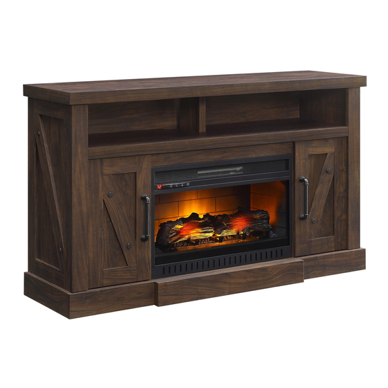
54 in. Media Console Infrared Electric Fireplace
ATTACH YOUR RECEIPT HERE
P
Serial Number
Please call for replacement parts or assistance: 1-866-942-5362
Pacific Standard Time: 8:30 a.m. – 4:30 p.m., PST, Monday to Friday
Printed in China
On-line Video Instruction Guides
Go to www.guides.sellpoints.com to view step-by-step instructional videos for
operating the fireplace. Enter the following product number on the website.
WSLWFP54-6
Purchase Date
Or visit our web site: www.whalenfurniture.com
1
ITEM # 1031287
MODEL # WSLWFP54-6
Español p. 15
Advertisement

Subscribe to Our Youtube Channel
Related Manuals for Whalen WSLWFP54-6


Summary of Contents for Whalen WSLWFP54-6
- Page 1 *SF127-26AI2D-CFI WSLWFP54-6 Remote Control 6-Buttom *SF127-26AI2D-RC6B ITEM # 1031287 54 in. Media Console Infrared Electric Fireplace MODEL # WSLWFP54-6 Español p. 15 ATTACH YOUR RECEIPT HERE Serial Number Purchase Date Please call for replacement parts or assistance: 1-866-942-5362 Pacific Standard Time: 8:30 a.m. – 4:30 p.m., PST, Monday to Friday Or visit our web site: www.whalenfurniture.com...
-
Page 2: Table Of Contents
TABLE OF CONTENTS PACKAGE CONTENTS Wood Dowel Installation...................... 2 Package Contents....................... 3 Hardware Contents......................4 Safety Information....................... 5 Preparation ......................... 5 Assembly Instructions......................6 Care and Maintenance ......................13 One-Year Warranty ......................13 Replacement Parts List ..................... 14 WOOD DOWEL INSTALLATION 1. Apply glue to each dowel prior to inserting the dowel into the hole. Excess glue can be wiped off with damp cloth. -
Page 3: Hardware Contents
SAFETY INFORMATION HARDWARE CONTENTS (shown actual size) Please read and understand this entire manual before attempting to assemble, operate or install the product. • Do not allow children to climb or play in or around this product. • Use this unit for its intended purpose only. Do not use shelves as step ladder. M3.5 x 15 mm •... -
Page 4: Assembly Instructions
ASSEMBLY INSTRUCTIONS ASSEMBLY INSTRUCTIONS 1a. Unpack the unit and confirm that you have all the hardware and 4. Glue four wood dowels (CC) into the bottom inner holes of required parts. Assemble the unit on a carpeted floor or the empty both lower partition panels (F and G) and attach them to the carton to avoid any scratch. - Page 5 ASSEMBLY INSTRUCTIONS ASSEMBLY INSTRUCTIONS 10. Align and attach the upper partition panel (H) to the center shelf 7. With the pilot holes as a guide, fasten two corner connectors (PP) (C) with one wood dowel (CC) and two long screws (FF). to the joints where the front stretcher (J) meets the side frames The molding faces front of the unit (D and E), using four short screws (DD) per connector.
- Page 6 ASSEMBLY INSTRUCTIONS ASSEMBLY INSTRUCTIONS Follow these steps if you want to change your fireplace door 13a. Pick up the upper back panel (Q) and align the drilled holes panels from wood (S) to glass (P). Otherwise, skip to Step 17. with the pilot holes on the back of the top panel (A).
- Page 7 ASSEMBLY INSTRUCTIONS CARE AND MAINTENANCE 19. Using the pilot holes as a guide, align and attach L-shaped metal A touch-up pen has been provided to minimize the small nicks or scratches that may occur during assembly or shipping. braces (LL) to the bottom panel (B) by screwing one washer To clean and care for your furniture: head screw (EE) in each.
- Page 8 Inserto de chimenea completo WSLWFP54-6 *SF127-26AI2D-RC6B Control remoto 6-botones ARTÍCULO # 1031287 Consola con chimenea eléctrica infrarroja de 54” MODELO # WSLWFP54-6 Español p. 15 ADJUNTAR SU RECIBO AQUÍ Fecha de compra Número de serie Por favor llame para repuestos o asistencia: 1-866-942-5362 Hora estándar del pacífico: 8:30 a.m.
- Page 9 TABLA DE CONTENIDO CONTENIDO DEL PAQUETE Instalación de clavija de madera..................16 Contenidos del empaque....................17 Contenidos de atículos de ferretería................. 18 Información de seguridad....................19 Peparación ........................19 Instrucciones de ensamble....................20 Cuidado y matenimiento....................27 Garantía de un año ......................27 Lista de partes de repuesto....................
- Page 10 INFORMACIÓN DE SEGURIDAD CONTENIDO DE HERRAJE (mostrado tamaño real) Por favor lea y comprenda el manual entero antes de intentar ensamblar o instalar el producto. • No permita que los niños se suban o jueguen en o alrededor de este producto. •...
- Page 11 INSTRUCCIONES DE ENSAMBLE INSTRUCCIONES DE ENSAMBLE 1a. Desempacar la unidad y confirmar que se tiene todo el herraje y 4. Pegar cuatro clavijas de madera (CC) en los orificios interiores partes requeridas. Ensamble la unidad sobre un área con alfombra o inferiores des los paneles divisorios inferiores (F y G) y adjuntarlo sobre el cartón para evitar daños a las piezas.
- Page 12 INSTRUCCIONES DE ENSAMBLE INSTRUCCIONES DE ENSAMBLE 10. Alinear y adjuntar el panel divisorio superior (H) a la repisa 7. Con los agujeros piloto como guía, ajuste dos connectores central (C) con una clavija de madera (CC) y dos tornillos esquina (PP) en la junta donde la soporte frontal inferior La moldura apunta hacia el frente de la unidad largos (FF).
- Page 13 INSTRUCCIONES DE ENSAMBLE INSTRUCCIONES DE ENSAMBLE Siga estos pasos si desea cambiar los paneles de la puerta del 13a. Recoger el panel posterior superior (Q) y alinear los agujeros mueble para televisor desde madera a vidrio. De lo contrario, perforados con los agujeros piloto sobre el parte posterior del vaya al Paso 17.
- Page 14 INSTRUCCIONES DE ENSAMBLE CUIDADO Y MANTENIMIENTO 19. Usar los agujeros piloto como una guía, alinear y colocar Un plumón de retoque se ha proporcionado para minimizar las muescas pequeñas o rayaduras que puedan ocurrir durante el abrazaderas de metal en forma de L (LL) al panel inferior (B) montaje o el envío.
Need help?
Do you have a question about the WSLWFP54-6 and is the answer not in the manual?
Questions and answers