
Related Manuals for Ferno FL1


Summary of Contents for Ferno FL1
- Page 1 FERNO ® Installation and Users’ Manual When It’s Critical ® FL1 Fastener Read this Manual July 2010 GLO and Retain for Pub. No. 234-3458-00 Future Reference...
-
Page 2: Ferno Customer Relations
Limited Warranty statement The products sold by Ferno are covered by a limited warranty, which is printed on all Ferno invoices. The complete terms and conditions of the limited warranty, and the limitations of liability and disclaimers, are also available upon request by calling Ferno at 1.800.733.3766 or... -
Page 3: Table Of Contents
7 - Parts and Service ___________________________ 22 4.1 Securing the Transporter In the Fastener ______ 8 7.1 Service - Worldwide _____________________ 22 Training Record ______________________________ 23 4.2 Releasing the Transporter From the Fastener ___ 8 Maintenance Record ___________________________ 23 © Ferno-Washington, Inc 234-3458-00 July 2010... -
Page 4: Safety Information
Improper use of the fastener can cause injury. Use the Compatibility fastener only for the purpose described in this manual. For the purpose of this notice, all Ferno transporters are an improper transporter can cause injury. Use only a included under the generic term, “cot”. -
Page 5: Symbol Glossary
A sample training ● record sheet is provided on page 23. WarnIng Untrained operators can cause injury or be injured. Permit only trained personnel to operate the fastener. © Ferno-Washington, Inc 234-3458-00 July 2010... -
Page 6: About The Fastener
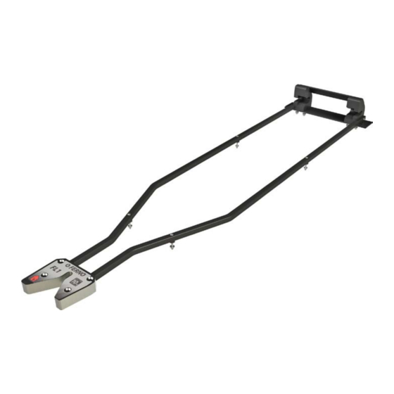
FL1 Fastener 3 - abOUT The FasTener 3.1 Description WarnIng The Ferno FL1 Fastener (called the fastener in this manual) ® Improper use of the fastener can cause injury. Use is designed to secure a compatible Ferno transporter in ®... -
Page 7: Before Placing The Fastener In Service
The fastener must be properly installed by professional Most general specifications are rounded to the nearest whole ● personnel (see Before You Begin, page 11). number. For more information, contact Ferno Customer Relations (page 2) or your Ferno distributor. Confirm that the fastener operates properly. See ●... -
Page 8: Using The Fastener
Lock Box Transporter Outline Figure 1 - Loading the Transporter Into the Fastener Release Button Transporter Fastener Transporter Loading-End Post Enters Here Crosstube Enters Here Figure 2 - Lock Box Figure 3 - Towers © Ferno-Washington, Inc 234-3458-00 July 2010... -
Page 9: Maintenance
Cleaning (this page) • • Inspecting (page 10) Wipe all surfaces with disinfectant. Follow the disinfectant manufacturer’s instructions for application method and contact time. Ferno recommends you inspect the fastener for damage as you disinfect it. Important Disinfectants cleaners containing bleach, 5.3 Cleaning the Fastener... -
Page 10: Inspecting The Fastener
Has exposure to the environment caused noticeable plate. damage? If inspection indicates the components are pulling through the backing plate, take the fastener out of service immediately and install a new fastener with new backing plates. © Ferno-Washington, Inc 234-3458-00 July 2010... -
Page 11: Installing The Fastener
To comply with CEN standards, install the fastener according to all applicable EN guidelines and the instructions in this manual. The FL1 Fastener, when installed properly and when used with a Mondial transporter and RS2, RS2, or RS4 stretcher, meets or ™... -
Page 12: Items Supplied And Required
M6x1x20 Button Head Rail Screw M6x1x60 Button Head Rail Screw M6x1x16 Flat Head Machine Screw M8 Center Lock Nut M6 Center Lock Nut Tower Plate (14 holes) Tower Crossbar (8 holes) Loctite (Red) Lock Box ® ™ Capsule © Ferno-Washington, Inc 234-3458-00 July 2010... -
Page 13: Transporter Placement
This information will help determine the proper position for the fastener. Refer to the current CEN standards to properly position the transporter within the “treatment area” specified in EN 1789. The overall dimensions of transporters compatible with the fastener are shown at right © Ferno-Washington, Inc 234-3458-00 July 2010... -
Page 14: Marking The Ambulance Floor, Table Or Tray
Centerline with its flat, long end on this Ambulance Doors Drilling Points new line (Figure 5). Figure 5 - Marking the Lock-Box Mounting Points Use a marker, pen, or other tool to mark the four drilling points for the lock box on the floor, table, or tray. © Ferno-Washington, Inc 234-3458-00 July 2010... - Page 15 If there is interference between the rail and lock box, the measurements are incorrect. Note: The four mounting points for the fastener rails will be determined as the fastener is set in place. © Ferno-Washington, Inc 234-3458-00 July 2010...
-
Page 16: Assembling The Fastener
(away from the towers). Using a 4 mm hex key and the six prepared screws, attach the plate to the towers (Figure 8). Completely tighten the screws. Wipe off excess Loctite ® © Ferno-Washington, Inc 234-3458-00 July 2010... - Page 17 If the gap between the lock box and rail-ends is ○ more than 25 mm (1"), or if the rails interfere with the lock-box placement, re-measure and mark the floor, table or tray for the fastener installation. © Ferno-Washington, Inc 234-3458-00 July 2010...
-
Page 18: Drilling The Holes And Installing The Backing Plates
(Figure 12), using a full manual. Consult the ambulance manufacturer for penetration weld. assistance. Using the guide holes, drill completely through the ambulance floor, table, or tray, and the backing plates, using an 10 mm drill bit. © Ferno-Washington, Inc 234-3458-00 July 2010... - Page 19 If mounting to an ambulance tray, the tray must be at least ● 1.75 mm thick. Floating Table or Tray (if present) Tower Backing Plate Lock Box Backing Plate Figure 12 - Backing Plate Placement © Ferno-Washington, Inc 234-3458-00 July 2010...
-
Page 20: Mounting The Fastener
(see Items Supplied and Required, page 12). Note: The studs must extend beyond the nuts a minimum of 19 mm when completely tightened later (See Securing the Fastener, page 21). Use longer screws if needed. © Ferno-Washington, Inc 234-3458-00 July 2010... -
Page 21: Testing The Fastener
When the installation passes the test, the fastener may be placed in service. Slide a nylon spacer (supplied) between the rail and the ambulance floor, table, or tray. Rail Bolt Mounting Points 117.5 mm (4-5/8") Figure 15 - Securing the Rails © Ferno-Washington, Inc 234-3458-00 July 2010... -
Page 22: Parts And Service
To order parts or for professional product repair, contact Improper parts and service can cause injury. Use your Ferno distributor. Your distributor is the only agent only Ferno parts and Ferno-approved service on the authorized by Ferno to manage, service, and repair Ferno fastener. -
Page 23: Training Record
FL1 Fastener TraInIng reCOrD Date Name Training Method MaInTenanCe reCOrD Date Maintenance Performed © Ferno-Washington, Inc 234-3458-00 July 2010...
Need help?
Do you have a question about the FL1 and is the answer not in the manual?
Questions and answers