Table of Contents
Advertisement
Quick Links
Advertisement
Table of Contents

Related Manuals for Ferno VIPER F1002


Summary of Contents for Ferno VIPER F1002
- Page 1 VIPER LOADING SYSTEM Operation and Maintenance Manual Rev A, 27.6.2022...
-
Page 3: Table Of Contents
Contents Introduction � � � � � � � � � � � � � � � � � � � � � � � � � � � � � � � � � � � � � � � � � � � � � � �4 Meaning of special symbols �... -
Page 4: Introduction
Introduction Thank you for purchasing the VIPER LOADING SYSTEM� In order to make full use of all the product's features, read the entire operation manual carefully and store the manual so that it is available for all potential users� The manual contains general instructions for the use, operation and maintenance of the product�... -
Page 5: Limited Warranty
Limited warranty Viper comes with a two-year warranty to cover defects in material and workmanship� This warranty does not cover: • standard wear and tear, • incorrect assembly, • incorrect follow-up maintenance, • the installation of parts or accessories not originally intended for (or not compatible with) the given product, •... - Page 6 Summary of safety precautions PRECAUTION • The VIPER loader and fastener system is intended only for the fastening of the transporter with a stretcher or the monobloc for which the fastener is certified. • For transport without the transporter / monobloc, always check that all the loader components are in their secured position�...
- Page 7 PRECAUTION • The product may only be disposed of at the end of its service life by the manufacturer or an authorised service partner� • If a defect is found in the product, stop using it immediately and contact an authorised service partner or the manufacturer directly�...
-
Page 8: Technical Specifications
Technical specifications Length (A) 200 cm Width (B) 57 cm Height (C) 26 cm Length with extended arm (D) 311 cm Weight 66 kg Maximum load capacity 400 kg The figures are rounded off to the nearest whole number. CAUTION The VIPER loader and fastener system is intended only for fastening of the transporter with a stretcher or the monobloc for which the fastener is certified. -
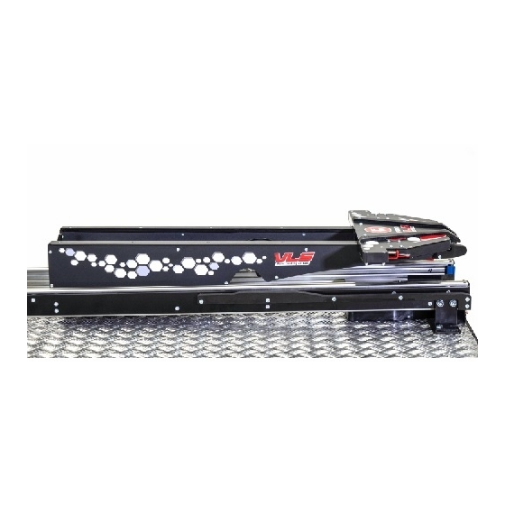
Page 9: Identification Of Components
Identification of components Front fasteners Rear fastener Extension arm Slider Linear guide rail Equipment consisting of a slider, an extension arm and linear guides enables loading of the transporter / monobloc into the vehicle� The transporter / monobloc is secured by means of the front and rear fasteners� General principles of operation Compatibility Use the fastener only with VIPER transporters / monoblocks�... -
Page 10: Position Of Components In The Vehicle
Position of components in the vehicle The position of the individual loader components in the vehicle is precisely defined: - The linear guide rails are fully retracted� - The extension arm is in the outermost position relative to the rear edge of the loader�... -
Page 11: Operation Of The Loader Without The Transporter / Monobloc
Operation of the loader without the transporter / monobloc Pulling out of the vehicle To pull the loader out of the vehicle, lift the extension arm control lever and hold it throughout the outward movement� When the loader reaches the outermost position, release the control lever�... -
Page 12: Pushing Into The Vehicle
POSITION OF LOADER COMPONENTS PULLED OUT OF THE VEHICLE Extension arm in the outermost position secured against reverse movement Linear guide rails in the outermost position secured against reverse movement Pushing into the vehicle To push the loader into the vehicle, lift the extension arm control lever and hold it throughout the inward movement�... -
Page 13: Slider And Extension Arm
INCORRECT POSITION OF THE EXTENSION ARM PUSHED INTO THE VEHICLE CAUTION For transport without the transporter / monobloc, always check that all the loader components are in their secured position� Never leave the linear guide rails or the extension arms unsecured� Otherwise, there is a risk of serious injury�... - Page 14 By pressing the release levers, the slider is released and can move along the extension arm� Both release levers must be pressed simultaneously to release the slider� No movement is possible if only one lever is pressed� After pressing the lever, a catch is ejected to connect the structure of the transporter / monobloc with the slider�...
- Page 15 When the slider moves into the vehicle, the lifting lever of the extension arm is released and lifts up� When the slider moves out of the vehicle, the lifting lever is secured in the lower (horizontal) position. The function of the lifting lever is explained in detail in Chapter "Loading into the vehicle"...
-
Page 16: Operation Of The Loader With The Transporter / Monobloc
Operation of the loader with the transporter / monobloc Loading into the vehicle Step 1 Pull the extension arm all the way out of the vehicle and verify that it is in the outermost position secured against reverse movement� Step 2 Adjust the position of the transporter / monobloc so that its front section is in the permitted height range�... - Page 17 Step 3 While advancing onto the slider try to align the transporter / monobloc lengthwise to the loader� LENGTHWISE ALIGNMENT WITH THE LOADER After both slider levers are pressed by the rollers (a part of the transporter / monobloc) the slider is released and the transporter / monobloc can be freely pushed into the vehicle�...
- Page 18 Step 4 Manoeuvre the transporter / monobloc all LOCKED LIFTING LEVER the way to the end of the extension arm� As the transporter / monobloc advances, the lifting lever is released and it is smoothly guided along the sloping surface lock, which locks it and secures the transporter / monobloc against reverse movement�...
- Page 19 MAXIMUM HEIGHT DISTANCE BETWEEN THE EXTENSION ARM AND THE TRANSPORTER / MONOBLOC Max 9 cm Max 9 cm Step 5 CONTROL PANEL Press and hold the left button on the control panel of the transporter / monobloc� The transporter / monobloc will first lower onto the extension arm and the undercarriage with the wheels will then be raised�...
- Page 20 CATCH PREVENTING THE TRANSPORTER / MONOBLOC FROM TIPPING BACKWARDS FOOT SECTION SECURED SAFETY CATCH ANCHOR TUBE Anchor tube Safety catch CAUTION As the transporter / monobloc rests on the extension arm, do not overload the part of the structure at the feet of the transported person� Otherwise, there is a risk of damage to the product�...
- Page 21 NOTE In the outermost position (when the loader is fully extended from the vehicle), an auxiliary spring is activated to partially prevent spontaneous movement into the vehicle� As you push into the vehicle, use slight pressure to disengage the spring� LIFTING THE UNDERCARRIAGE WITH THE WHEELS TO THE HIGHEST POSITION 1�...
- Page 22 HORIZONTAL PLUG LOCKS THE VERTICAL PLUGS LOCK THE TWO REAR PIN FRONT PINS Vertical plug Horizontal plug Front pin Rear pin Fastener lever in locked position LOCKED AND FRONT AND REAR FASTENERS Front pin Rear pin of the transporter / monobloc of the transporter / monobloc Fastener lever in the Vertical plug...
-
Page 23: Unloading From The Vehicle
CAUTION Always check that the rear horizontal and front vertical plugs are fully locked. The fastener lever must be fully raised in the horizontal position. If the fastener is not locked correctly, there is a risk of serious injury� INCORRECT POSITION OF THE FASTENER LEVER Unloading from the vehicle Step 1... - Page 24 UNLOCKING THE FASTENER 2� 1� Fastener lever CAUTION When the loader is fully extended from the vehicle, an auxiliary spring is activated to partially prevent reverse movement� It should be noted that this is not a sufficient safeguard. Hold the transporter / monobloc firmly until it is completely unloaded from the vehicle�...
- Page 25 Step 2 CONTROL PANEL Press the right button on the control panel� The undercarriage with the wheels will start lowering� Keep pressing the button until the movement stops automatically� The wheels will touch the ground and the transporter / monobloc will rise slightly�...
-
Page 26: Charging In The Vehicle
Charging in the vehicle The rear fastener is fitted with charging contact surfaces. Charging commences automatically when the transporter / monobloc is inserted into the fastener and connected to the charging connectors� Charging starts within a few seconds after connection� More detailed information about the charging of the battery can be found in the transporter / monobloc instructions for use�... - Page 27 CONNECTION WITH THE TRANSPORTER / MONOBLOC CHARGING CONNECTORS Connectors Contact surface 12 V (+) Contact surface GND (-) The following shows the voltage and current values during charging in the vehicle The voltage on the contact surfaces (part of the rear fastener) is decisive for charging and, as a rule, it is lower than on the car battery clamps�...
-
Page 28: Space Requirements At The Rear Of The Vehicle
Space requirements at the rear of the vehicle The vehicle body should always be adapted to provide sufficient space for movement of the undercarriage with the wheels while loading or unloading the transporter / monobloc into or out of the vehicle� The table below shows the relationship between the floor height (A) and the length of the space from the undercarriage front edge to the loader rear edge (B)�... -
Page 29: Installation In Vehicle
Installation in vehicle CAUTION The fastener may only be installed by a trained person or authorised service partner� Step 1 - Preparing the mounting holes in the floor Prepare the holes in the floor of the vehicle following the diagram below. Ensure that the fastener is placed correctly in relation to the edges of the table or floor. - Page 30 LOCATION OF THE FASTENER RELATIVE TO THE THE EDGES OF THE TABLE OR FLOOR Front pin axis Transporter / monobloc wheels Front pin pitch Transporter / monobloc outer perimeter Dimension of the widest part of the transporter / monobloc Rear pin axis Transporter / monobloc wheels Rear loader...
- Page 31 Step 2 - Removing the rear fastener cover Loosen the eight bolts from the side covers on the rear fastener and carefully remove both covers� This will disengage the spring located in the opening of the side of the fastener� Store the spring in a safe place� INSTALLING THE REAR FASTENER SIDE COVERS Spring opening Step 3 - Attaching the fastener to the floor...
- Page 32 FRONT AND REAR FASTENER SECTION INSTALLATION The image is for illustration purposes and contains only some of the loader components. NOTE The connecting material for installing the fastener is not supplied� CAUTION When installing the fastener on the floor, use only the connecting material specified by the manufacturer and do not alter the structure in any way.
-
Page 33: Preventive Maintenance
Preventive maintenance Maintenance plan The product requires regular maintenance� Draw up a maintenance plan and proceed accordingly� The table below shows the minimum maintenance intervals� Activity Frequency Cleaning and disinfection After each use Lubrication As needed (lubrication may only be performed by a person with the appropriate training) Inspection Every month... -
Page 34: Lubrication
Lubrication Lubricate with Interflon Fin Lube TF. CAUTION Lubrication may only be performed by a person with the appropriate training� Improper lubrication can cause damage to the mechanisms� Disposal When the product reaches the end of its service life, contact the manufacturer or an authorised service centre, who will arrange the disposal of the product in an appropriate manner�... -
Page 35: Maintenance Records
Maintenance records Description of maintenance Date Performed by performed...
Need help?
Do you have a question about the VIPER F1002 and is the answer not in the manual?
Questions and answers