Table of Contents
Advertisement
Quick Links
NXP Semiconductors
User's Guide
WCT1012 15W Single Coil TX V3.1
Reference Design System User's
Guide
1 Introduction
This document describes how to use the 15W
medium power wireless charger transmitter
designed by NXP. The reference solution is
compliant with Qi Medium Power V1.2.2
specification. It is a low-cost reference solution,
which can be easily customized through the
FreeMASTER GUI tool.
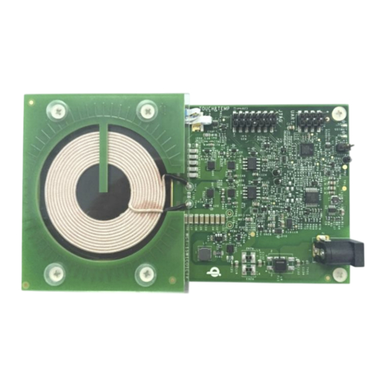
Figure 1. WCT-15W1COILTX reference board
© 2017 NXP B.V.
_______________________________________________________________________
Document Number: WCT1012V31SYSUG
Contents
1
2
3
4
5
6
7
8
9
Rev. 0 , 02/2017
1
2
2
2
3
6
11
42
45
Advertisement
Table of Contents

Subscribe to Our Youtube Channel
Related Manuals for NXP Semiconductors WCT1012


Summary of Contents for NXP Semiconductors WCT1012
-
Page 1: Table Of Contents
Document Number: WCT1012V31SYSUG NXP Semiconductors User’s Guide Rev. 0 , 02/2017 WCT1012 15W Single Coil TX V3.1 Reference Design System User’s Guide Contents 1 Introduction Introduction This document describes how to use the 15W medium power wireless charger transmitter System Features... -
Page 2: Wct-15W1Coiltx (Mpa4) Reference Board
MP TX runs with RX to transfer power from TX to RX as well as send messages to RX by frequency shift keyed modulation (FSK), as shown in this figure. Figure 2. Wireless Charging System overview WCT1012 15W Single Coil TX V3.1 Reference Design System User’s Guide, Rev. 0, 02/2017 NXP Semiconductors... -
Page 3: Hardware Description
To find WPC Qi information, visit www.wirelesspowerconsortium.com/developers/. 5 Hardware Description 5.1 Reference board block diagram Figure 3. Block diagram WCT1012 15W Single Coil TX V3.1 Reference Design System User’s Guide, Rev. 0, 02/2017 NXP Semiconductors... - Page 4 Controller The NXP WCT1012 chip is the central controller of WCT-15W1COILTX board. It has rich peripherals with low power consumption. It processes communication signals, controls power transfer start/stop, and controls a full bridge PWM inverter for output power control.
- Page 5 5-a and Figure 5-b. The Q Factor measurement circuit is also different. See Section 6.1 detailed information. Figure 5-a. Free resonance Q measurement Figure 5-b. External driver Q measurement WCT1012 15W Single Coil TX V3.1 Reference Design System User’s Guide, Rev. 0, 02/2017 NXP Semiconductors...
-
Page 6: Foreign Object Detection Architecture
TX surface the first time powering up after flashing a new image. Figure 6. Quality factor threshold example WCT1012 15W Single Coil TX V3.1 Reference Design System User’s Guide, Rev. 0, 02/2017 NXP Semiconductors... - Page 7 Figure 7. Resonance signal The circuit for free resonance Q measurement is as shown in Figure 8, which is sampling circuit of signal on resonance capacitors. WCT1012 15W Single Coil TX V3.1 Reference Design System User’s Guide, Rev. 0, 02/2017 NXP Semiconductors...
- Page 8 (at resonant frequency) Figure 9. External Driver Q factor measurement method The sample circuits include driver signal sampling and resonance signal sampling, as shown in Figure WCT1012 15W Single Coil TX V3.1 Reference Design System User’s Guide, Rev. 0, 02/2017 NXP Semiconductors...
- Page 9 Received Power , i.e. , provides the power absorption in Foreign Objects, as shown in the following figure. Figure 11. Power loss illustrated WCT1012 15W Single Coil TX V3.1 Reference Design System User’s Guide, Rev. 0, 02/2017 NXP Semiconductors...
- Page 10 Transmitted Power using linear interpolation. Alternatively, the Power Transmitter can calibrate the reported Received Power. Take the calibrated Transmitted Power as an example: WCT1012 15W Single Coil TX V3.1 Reference Design System User’s Guide, Rev. 0, 02/2017 NXP Semiconductors...
-
Page 11: Getting Started
For example, when TX coil or main power components are changed, it is better to calibrate to get the Foreign Object Detection (FOD) working. This document describes the basic debugging environment on WCT1012. For MP software details, see the WCT1012 TX V3.1 Library User’s Guide (WCT1012V31LIBUG). - Page 12 Figure 12. Debugging connections WCT1012 15W Single Coil TX V3.1 Reference Design System User’s Guide, Rev. 0, 02/2017 NXP Semiconductors...
- Page 13 For details about the P&E-Multilink FX debugger, visit nxp.com and search for “U-MULTILINK-FX”. Then the U-MULTILINK-FX: Universal Multilink FX High-Speed Development Interface page is displayed. WCT1012 15W Single Coil TX V3.1 Reference Design System User’s Guide, Rev. 0, 02/2017 NXP Semiconductors...
- Page 14 Multilink to the MP board. The correct direction to plug-in the cable is shown in these figures. USB TAP Red line linked to Pin 1 Figure 14. Debugger connecting WCT1012 15W Single Coil TX V3.1 Reference Design System User’s Guide, Rev. 0, 02/2017 NXP Semiconductors Debugger board J5 pin #14 –> A11 board J4 pin #1...
- Page 15 Device Manager, as shown in these figures. USB TAP P&E Multilink Figure 15. USB TAP debugger plugged in Figure 16. P&E multilink debugger plugged in WCT1012 15W Single Coil TX V3.1 Reference Design System User’s Guide, Rev. 0, 02/2017 NXP Semiconductors...
- Page 16 OSJTAG Figure 17. OSJTAG debugger plugged in WCT1012 15W Single Coil TX V3.1 Reference Design System User’s Guide, Rev. 0, 02/2017 NXP Semiconductors...
- Page 17 Open CodeWarrior version 10.7, and set the workspace to WCT1012 example project. Figure 18. Setting the CodeWarrior version 10.7 workspace (1) Figure 19. Setting the CodeWarrior version 10.7 workspace (2) WCT1012 15W Single Coil TX V3.1 Reference Design System User’s Guide, Rev. 0, 02/2017 NXP Semiconductors...
- Page 18 Use the downloaded.zip file as the local update archive: Click the Add... button, and then click Archive... to point to the com.freescale.mcu10_7.Wireless_Charging_MWCT101x.win.sp.v1.0.1.zip file to be downloaded. Figure 22. Updating the MCU v10.7 service package (1) WCT1012 15W Single Coil TX V3.1 Reference Design System User’s Guide, Rev. 0, 02/2017 NXP Semiconductors...
- Page 19 If the CodeWarrior Projects window is not displayed, open it through Window –> Show View –> CodeWarrior Projects. Figure 24. Importing a project (1) WCT1012 15W Single Coil TX V3.1 Reference Design System User’s Guide, Rev. 0, 02/2017 NXP Semiconductors...
- Page 20 Figure 25. Importing a project (2) Select the project directory, as shown in this figure. Figure 26. Importing a Project (3) WCT1012 15W Single Coil TX V3.1 Reference Design System User’s Guide, Rev. 0, 02/2017 NXP Semiconductors...
- Page 21 Right-click the project name wct1012demo: demo_sdm_release and then you can select Build Project, Clean Project, or Close Project. You can also perform building from Project. WCT1012 15W Single Coil TX V3.1 Reference Design System User’s Guide, Rev. 0, 02/2017 NXP Semiconductors...
- Page 22 In Download Configurations, select a download configuration according to your build configurations and debugger type, USB TAP, PnE Multilink, or OSJTAG. Debug Debug Connections Click to download Figure 30. Downloading the project WCT1012 15W Single Coil TX V3.1 Reference Design System User’s Guide, Rev. 0, 02/2017 NXP Semiconductors...
- Page 23 To flash an .elf file, perform these steps: 1. From the Flash Programmer drop-down list, select Flash File to Target. Figure 32. Bin file download (1) WCT1012 15W Single Coil TX V3.1 Reference Design System User’s Guide, Rev. 0, 02/2017 NXP Semiconductors...
- Page 24 Figure 33. Bin file download (2) 3. Enter a connection name and click New to create a target. Figure 34. Bin file download (3) WCT1012 15W Single Coil TX V3.1 Reference Design System User’s Guide, Rev. 0, 02/2017 NXP Semiconductors...
- Page 25 6. Set the memory configuration file path. For the MWCT1012 chip, it is MWCT1012.mem, located under the CodeWarrior version 10 installation folder. Then, click Finish. The general path is: C:\Freescale\CW MCU v10.7\MCU\lib\wizard_data\DSC\DataBase\mem_files WCT1012 15W Single Coil TX V3.1 Reference Design System User’s Guide, Rev. 0, 02/2017 NXP Semiconductors...
- Page 26 Figure 38. Bin file download (7) 8. Set the Bin file path. Before downloading, save the configuration to the workspace for future downloading. Click Erase and Program. WCT1012 15W Single Coil TX V3.1 Reference Design System User’s Guide, Rev. 0, 02/2017 NXP Semiconductors...
- Page 27 9. The flashing progress is displayed in the CodeWarrior version 10 console window. After flashing is completed, reset the board to make MWCT1012 run. Figure 40. Bin file download (9) WCT1012 15W Single Coil TX V3.1 Reference Design System User’s Guide, Rev. 0, 02/2017 NXP Semiconductors...
- Page 28 WCT1012 15W Single Coil TX V3.1 Runtime Debug User’s Guide (WCT1012V31RTDUG) for calibration and MP parameters tuning. For the FreeMASTER tool, see www.nxp.com/products/power-management/wireless-charging-ics/freemaster-run-time-debugging-tool: FREEMASTER. Figure 41. FreeMASTER GUI tool WCT1012 15W Single Coil TX V3.1 Reference Design System User’s Guide, Rev. 0, 02/2017 NXP Semiconductors...
- Page 29 Set the symbol file for your project. Select the symbol file in FreeMASTER Project –> Options –> MAP Files, as shown in the following figure. Figure 42. Selecting symbol file WCT1012 15W Single Coil TX V3.1 Reference Design System User’s Guide, Rev. 0, 02/2017 NXP Semiconductors...
- Page 30 Perform settings for using P&E Multilink FX debugger. Select FreeMASTER BDM JTAG/OnCE in Project –> Options –> Comm, as shown in the following figure. Figure 44. Options dialog box WCT1012 15W Single Coil TX V3.1 Reference Design System User’s Guide, Rev. 0, 02/2017 NXP Semiconductors...
- Page 31 Rebuild the demo, and download it according to the used debugger. c. Link the SCI port on OSJTAG to MP board as shown in the following figure. Figure 45. Using OSJTAG for FreeMASTER connection WCT1012 15W Single Coil TX V3.1 Reference Design System User’s Guide, Rev. 0, 02/2017 NXP Semiconductors...
- Page 32 19200. It can be found in Computer –> Manage –> System Tools –> Device Manager –> Ports. Right-click OSBDM/OSJTAG and choose Properties. Then the baud rate can be changed as shown in the following figure . WCT1012 15W Single Coil TX V3.1 Reference Design System User’s Guide, Rev. 0, 02/2017 NXP Semiconductors...
- Page 33 FreeMASTER tool, as shown in the following figure. Figure 48. Option dialog box f. Click the Start/Stop button to make the FreeMASTER connection work. WCT1012 15W Single Coil TX V3.1 Reference Design System User’s Guide, Rev. 0, 02/2017 NXP Semiconductors...
- Page 34 Put the MP Qi receiver on the charging pad, and make sure the coil is aligned and the load is in the allowed range (up to 15 W). The TX charges the RX properly. WCT1012 15W Single Coil TX V3.1 Reference Design System User’s Guide, Rev. 0, 02/2017 NXP Semiconductors...
- Page 35 LED1 LED2 Blink slow Blink slow Option-3 Choice-3 LED1 Blink slow Blink fast Blink fast Blink fast – – – – – – LED2 WCT1012 15W Single Coil TX V3.1 Reference Design System User’s Guide, Rev. 0, 02/2017 NXP Semiconductors...
- Page 36 Set up the WCT_MP test environment as shown in the following figure by using the DC power supply and electronic load for input source and output load. Get system efficiency by measuring input and output power. WCT1012 15W Single Coil TX V3.1 Reference Design System User’s Guide, Rev. 0, 02/2017 NXP Semiconductors...
- Page 37 MP TX can work under different control mode with different load and RX. Ch1: PWM1 Ch2: PWM2 Ch3: RX bus voltage Ch4: Coil current WCT1012 15W Single Coil TX V3.1 Reference Design System User’s Guide, Rev. 0, 02/2017 NXP Semiconductors...
- Page 38 Figure 57. Full bridge, frequency control System response measurement for load dump and load step test. Ch1: PWM1 Ch2: COMM Ch3: RX bus voltage Ch4: Coil current WCT1012 15W Single Coil TX V3.1 Reference Design System User’s Guide, Rev. 0, 02/2017 NXP Semiconductors...
- Page 39 Figure 58. System response on load dump Figure 59. System response on load step WCT1012 15W Single Coil TX V3.1 Reference Design System User’s Guide, Rev. 0, 02/2017 NXP Semiconductors...
- Page 40 The following figure shows one of the resonance signals (TP23).CH1 is PWM1 and CH2 is sampling voltage of resonance signal (TP23). Figure 61. Resonance signal during free resonance Q detection WCT1012 15W Single Coil TX V3.1 Reference Design System User’s Guide, Rev. 0, 02/2017 NXP Semiconductors...
- Page 41 62, CH1 is PWM1, CH2 is the sampling driver signal, and CH4 is the sampling resonance signal. The driver signal near resonant frequency is relatively low. Figure 62. External driver Q detection signals WCT1012 15W Single Coil TX V3.1 Reference Design System User’s Guide, Rev. 0, 02/2017 NXP Semiconductors...
-
Page 42: Flash Extension Of Wct1011
Replace the .mem and .tcl file in debugger configurations. Take “WCT_MPTX_1COIL_Demo_Release_SDM_OSJTAG” for example. The steps are as shown in Figure 63 Figure Figure 63. Changing the peripheral settings of debugger (1) WCT1012 15W Single Coil TX V3.1 Reference Design System User’s Guide, Rev. 0, 02/2017 NXP Semiconductors... - Page 43 Select the chip type MWCT1011. Figure 64. Changing the peripheral settings of debugger (2) Replace the .tcl file. WCT1012 15W Single Coil TX V3.1 Reference Design System User’s Guide, Rev. 0, 02/2017 NXP Semiconductors...
- Page 44 Figure 66. Change the peripheral settings of debugger (4) Click OK to save these changes. After finishing these steps, the 64KB flash of MWCT1011CFM is available. WCT1012 15W Single Coil TX V3.1 Reference Design System User’s Guide, Rev. 0, 02/2017 NXP Semiconductors...
-
Page 45: References
Rework List for the WCT-15W1COILTX Rev.3 Board (WCT1012V31RL) 10 Revision History Table 3. Revision history Revision number Date Substantive changes 02/2017 Initial release. WCT1012 15W Single Coil TX V3.1 Reference Design System User’s Guide, Rev. 0, 02/2017 NXP Semiconductors... - Page 46 How to Reach Us: Information in this document is provided solely to enable system and software implementers to use NXP products. There are no express or implied copyright licenses Home Page: granted hereunder to design or fabricate any integrated circuits based on the information nxp.com in this document.
Need help?
Do you have a question about the WCT1012 and is the answer not in the manual?
Questions and answers