ADC HiGain H2TU-C-231 Manual
Hide thumbs
Also See for HiGain H2TU-C-231:
- User manual (80 pages) ,
- Quick installation (7 pages) ,
- Manual (81 pages)

Related Manuals for ADC HiGain H2TU-C-231


Summary of Contents for ADC HiGain H2TU-C-231
- Page 1 HiGain HiGain ECHNICAL RACTICE H2TU-C-231 List 4E Line Unit Product Catalog: H2TU-C-231-L4E CLEI: VACJDLHE...
- Page 2 Contents herein are current as of the date of publication. ADC reserves the right to change the contents without prior notice. In no event shall ADC be liable for any damages resulting from loss of data, loss of use, or loss of profits, and ADC further disclaims any and all liability for indirect, incidental, special, consequential or other similar damages.
- Page 3 Upon receipt of the equipment: • Unpack each container and inspect the contents for signs of damage. If the equipment has been damaged in transit, immediately report the extent of damage to the transportation company and to ADC. Order replacement equipment, if necessary. •...
- Page 4 Inspecting Shipment LTPH-TP-1034-01, Issue 1 September 28, 2001 H2TU-C-231 List 4E...
-
Page 5: Table Of Contents
LTPH-TP-1034-01, Issue 1 Table of Contents ABLE OF ONTENTS Overview_____________________________________________________________________________ 1 Features .............................. 1 Compatibility ............................. 2 Applications ............................2 Front Panel___________________________________________________________________________ 3 Installation ___________________________________________________________________________ 7 Verification ............................8 Verification without an H2TU-R Remote Unit ..............8 Verification with an H2TU-R Remote Unit ................ 8 Provisioning __________________________________________________________________________ 9 Using the MODE and SEL Pushbuttons .................... - Page 6 Table of Contents LTPH-TP-1034-01, Issue 1 Testing _____________________________________________________________________________ 44 System Alarms..........................44 Alarm Option for Digital Loop Carrier (DLC) Feed ............45 Retiring System Alarms ....................45 Remote LOS and AIS Response ..................46 OCT55 Test Pattern with AMI Code....................46 Loopback Operation ........................
- Page 7 5. Inventory Screen.............................14 6. Config Menu..............................15 7. Config Menu - Standard Options (defaults shown)..................16 8. Config Menu - ADC Options (defaults shown) .....................16 9. Config Menu - Set Factory Defaults ......................26 10. Config Menu - Master Clear...........................27 11. Monitor Screen - Active Loopback with Alarms ...................28 12.
- Page 8 4. Logon Screen Menus ............................ 12 5. H2TU-C-231 List 4E Standard Config Menu Options .................. 17 6. H2TU-C-231 List 4E ADC Config Menu Options..................18 7. DS1 and DSX-1 24-Hour PM Threshold....................... 21 8. Response to H2TU-R DS1 Frame Conversion Options ................23 9.
-
Page 9: Overview
LTPH-TP-1034-01, Issue 1 Overview VERVIEW ® The H2TU-C-231 List 4E line unit is the Central Office (CO) side of a T1 transmission system. The HiGain HDSL2 product family is fully compliant with the HDSL2 standard ANSI T1.418-2000. Providing full-rate T1 access using a single copper pair, HDSL2 is a cost-effective solution that offers an open architecture. -
Page 10: Compatibility
Overview LTPH-TP-1034-01, Issue 1 – Supports the in-band 100 loopdown command for all loopback modes – Supports the in-band 100000 loopup command when SmartJack loopback (LPBK) option is enabled – Power Back Off Customer (PBOC) and Power Back Off Network (PBON) options for configuring power output levels •... -
Page 11: Front Panel
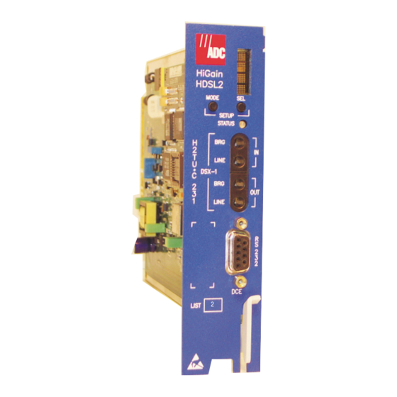
LTPH-TP-1034-01, Issue 1 Front Panel RONT ANEL Figure 1 shows the H2TU-C-231 List 4E front panel. Table 1 on page 4 describes the front-panel components. For pinout diagrams of the H2TU-C card-edge connector and craft port, refer to “Appendix A - Specifications” on page Front-panel display HiGain... - Page 12 Front Panel LTPH-TP-1034-01, Issue 1 Table 1. Front-Panel Description Front-Panel Feature Function Front-panel display Displays four-character status, provisioning, and alarm system messages. The front-panel display illuminates when power is initially applied. To conserve power, the display only remains on for 5 minutes. Using the MODE or SEL pushbuttons reactivate the display and restart the 5-minute timer.
-
Page 13: Front-Panel Display Messages
LTPH-TP-1034-01, Issue 1 Front Panel Table 2 lists the front-panel display messages. The four-character display reports the code of a pertinent alarm, loopback, or diagnostic message and, in some cases, is followed by a four-character message that modifies the first message with a value or current configuration setting. Table 2. - Page 14 Front Panel LTPH-TP-1034-01, Issue 1 Table 2. Front-Panel Display Messages (Continued) Message Full Name Description LOOPBACK MESSAGES CLOC Customer Local Loopback DS1 signal from customer is looped back to the customer at the H2TU-R. CREM Customer Remote Loopback DS1 signal from customer is looped back to the customer at H2TU-C. NLOC Network Local Loopback DSX-1 signal is looped back to the network at the H2TU-C.
-
Page 15: Installation
NSTALLATION Upon receipt of the equipment, inspect the contents for signs of damage. If the equipment has been damaged in transit, immediately report the extent of damage to the transportation company and to ADC. H2TU-C-231 CO Shelf Figure 2. Installing the H2TU-C-231 List 4E into a Shelf When installing an H2TU-C-231 in a chassis, be sure to wear an antistatic wrist strap. -
Page 16: Verification
Installation LTPH-TP-1034-01, Issue 1 ERIFICATION Once the H2TU-C-231 is installed, verify that it is operating properly. To do this, monitor the following: • Status LED • Status messages reported by the front-panel display (Table 2 on page Verification without an H2TU-R Remote Unit If there is no H2TU-R remote unit installed: Verify that the H2TU-C powers up. -
Page 17: Provisioning
LTPH-TP-1034-01, Issue 1 Provisioning ROVISIONING There are two methods for provisioning: • Use the MODE and SEL pushbuttons on the front panel of the H2TU-C to: – Set system options – Reset the H2TU-C to its factory default settings for system options –... -
Page 18: Resetting To Factory Defaults
Provisioning LTPH-TP-1034-01, Issue 1 Resetting to Factory Defaults All user options for the H2TU-C-231 List 4E (Table 6 on page 18) can be set to the factory default values using the MODE and SEL pushbuttons. To set the user options to their default values: Press the SEL pushbutton for 6 seconds until the following message appears: DFLT NO Press the SEL pushbutton while the DFLT NO message is displayed. -
Page 19: Logon Screen
LTPH-TP-1034-01, Issue 1 Provisioning To connect to a maintenance terminal: Connect a standard 9-pin terminal cable to the RS-232 craft port (Figure 1 on page 3) on the H2TU-C-231 List 4E front panel. Connect the other end of the cable to the serial port on the maintenance terminal. Start a terminal emulation program such as Procomm (emulating a VT100 terminal). -
Page 20: Logon Screen
Identifies the 100 most recent system events and reports the origin, date and time of occurrence, and message. Config Provides standard configuration options, ADC options, date and time setting, and a reset option (factory settings). Also provides a master clear option that clears all performance, alarm, and event log entries. -
Page 21: Provisioning Tasks
Setting Date and Time Monitor Performance Event Log Config Inventory Report Rlogon Help +----------------------+ | Standard Options -> | ADC Options -> Date and Time -> +-------------------------------+ | Date (mm/dd/yyyy): 09/01/2001| | Time (hh:mm[:ss]): 12:30:01 +-------------------------------+ ID: xxxx--xxxx—-xxxx--xxxx 09/01/2001 12:30:01 H2TU-C... -
Page 22: Setting Circuit Id Numbers
Provisioning LTPH-TP-1034-01, Issue 1 Setting Circuit ID Numbers The Inventory screen provides product information on all units in the system and allows the setting of the circuit and unit identification numbers. Monitor Performance Event Log Config Inventory Report Rlogon Help -------------------------- Product Information ----------------------------... -
Page 23: Configuring The System
Standard and ADC configuration options. Standard options are those that are supported by HiGain HDSL2 units when connected to units from other vendors. ADC options are an extended set of options that are only available when using HiGain units exclusively. For a description of each... - Page 24 | Fractional T1 Mode (FT1) : DIS +-----------------------------------------------+ Use <Spacebar> to cycle through option settings and <Enter> to activate ID: xxxx—-xxxx—-xxxx--xxxx 09/01/2001 12:30:01 H2TU-C System: OK___ Figure 8. Config Menu - ADC Options (defaults shown) September 28, 2001 H2TU-C-231 List 4E...
-
Page 25: H2Tu-C-231 List 4E Standard Config Menu Options
Table 5 below describes the Standard Config menu options and Table 6 on page 18 describes the ADC Config menu options. Selections in bold type are the factory default settings. Table 5. H2TU-C-231 List 4E Standard Config Menu Options Front-Panel... -
Page 26: H2Tu-C-231 List 4E Adc Config Menu Options
(PBOC) and customer to comply with the Enhanced template as defined in Section 6.1.4.2 Power Back Off of ANSIT1.E1.4. Network (PBON) Options” on page Table 6. H2TU-C-231 List 4E ADC Config Menu Options Front-Panel ADC Config Menu Display Selection Description Options... - Page 27 LTPH-TP-1034-01, Issue 1 Provisioning Table 6. H2TU-C-231 List 4E ADC Config Menu Options (Continued) Front-Panel ADC Config Menu Display Selection Description Options Code Special Loopback SPLB GNLB Configures the HiGain HDSL2 system to respond to the generic in-band Mode loopback codes.
- Page 28 Provisioning LTPH-TP-1034-01, Issue 1 Table 6. H2TU-C-231 List 4E ADC Config Menu Options (Continued) Front-Panel ADC Config Menu Display Selection Description Options Code Fractional T1 Mode Enables system response to DDS latching loopback commands for fractional T1 applications, CP disconnect, and trouble indication. For priority resolution, “Fractional T1...
- Page 29 LTPH-TP-1034-01, Issue 1 Provisioning DS1 BER (DBER) Option. The DS1 BER alarm occurs when any of the DS1 or DSX-1 performance monitoring parameters listed in Table 7 exceed the counts shown for the 24-hour period between 12:00:00 AM through 11:59:59 PM. These thresholds correspond to a 10 BER.
- Page 30 Provisioning LTPH-TP-1034-01, Issue 1 The SF-RAI to SF-RAI-CI option is only applicable in an all SF framing environment. If SF to ESF conversion is active (the CONV option is set to either ACON or FCON), the SF-RAI is converted into ESF-RAI in the FDL, regardless of the RACI setting. ESF-RAI to SF-RAI Overwrite (ROVR) Option.
-
Page 31: Extended Superframe Format
LTPH-TP-1034-01, Issue 1 Provisioning Table 8. Response to H2TU-R DS1 Frame Conversion Options ACON Option FCON Option Case Number NET Transmit CPE Transmit NET > CPE NET > CPE NET < CPE NET < CPE → → ESF ← SF ESF ←... - Page 32 Provisioning LTPH-TP-1034-01, Issue 1 Table 10. SuperFrame Format Frame Bits SF Number Terminal Framing Bit SuperFrame Signaling Bit Fractional T1 Mode (FT1) Option. Fractional T1 circuits can be used in feeder networks to provide frame relay service. If such circuits are maintained by a DDS test group, then these circuits must respond to DDS/DS0 latching loopback commands, the only tool test groups have at their disposal.
-
Page 33: Higain Hdsl2 Loopback Vs. Latching Sequence
LTPH-TP-1034-01, Issue 1 Provisioning minimum number of bytes when the loopback code is transmitted by a pre-programmed machine test pattern generator. These minimum number of bytes will most likely be exceeded when the codes are sent manually. Also, manual testing may inject random data signals between valid control sequences. The detection algorithm ignores these occurrences and only responds to valid control codes. -
Page 34: Clearing The History, Alarm, And Event Log Screens
Event Log Config Inventory Report Rlogon Help +----------------------+ | Standard Options -> | ADC Options -> | Date and Time -> | Master Clear Set Factory Defaults +----------------------+ SETTING FACTORY DEFAULTS...SERVICE MAY BE INTERRUPTED! ARE YOU SURE (Y/N)? ID: xxxx--xxxx—-xxxx--xxxx... - Page 35 Event Log Config Inventory Report Rlogon Help +----------------------+ | Standard Options -> | ADC Options -> | Date and Time -> Master Clear | Set Factory Defaults | +----------------------+ Clear ALL performance, alarm and event log entries. Are you sure (Y/N)? ID: xxxx--xxxx—-xxxx--xxxx...
-
Page 36: Monitoring System Activity And Performance
Monitoring System Activity and Performance LTPH-TP-1034-01, Issue 1 ONITORING YSTEM CTIVITY AND ERFORMANCE The HDSL2 system provides the following maintenance screens for monitoring system activity and assessing performance: • The Monitor screens provide a graphical representation of circuit activity and allow initiation of loopbacks. •... - Page 37 LTPH-TP-1034-01, Issue 1 Monitoring System Activity and Performance To initiate a loopback, press the SPACEBAR to cycle through the loopback choices. Press ENTER to make your choice. When prompted with the message: Are you sure (Y/N)?, press to initiate the loopback or cancel.
-
Page 38: Using The Performance Screens To View Performance Data
Monitoring System Activity and Performance LTPH-TP-1034-01, Issue 1 SING THE ERFORMANCE CREENS TO ERFORMANCE The Performance screens display: • DS1 and HDSL2 statistics in 31-day, 48-hour, 25-hour, and current history reports. • Alarm statistics for DS1 interfaces (Figure 21 on page 37 Figure 22 on page 37) or the HDSL2 (Figure 23... - Page 39 LTPH-TP-1034-01, Issue 1 Monitoring System Activity and Performance Monitor Performance Event Log Config Inventory Report Rlogon Help H2TU-C DS1 48 Hour History (Page 1 of 4) ------------------------------------------------------------------------------ Time CV-L ES-L SES-L UAS-L PDVS-L ES-P SES-P UAS-P *00:00 *01:00 *02:00 *03:00 *04:00 *05:00 *06:00...
-
Page 40: H2Tu-R Ds1 Current Statistics
Monitoring System Activity and Performance LTPH-TP-1034-01, Issue 1 Examples of current statistics screens are shown below. Figure 15 Figure 16 show statistics for the DS1 interface at the remote unit and line unit respectively. These screens report 1-day, 1-hour, and 15-minute statistics. Monitor Performance Event Log... - Page 41 LTPH-TP-1034-01, Issue 1 Monitoring System Activity and Performance Table 15. Error Acronyms Used on the DS1 Performance History Screens Error Acronym Description Error Acronym Description CV-L Code Violation - Line SES-P Severely Errored Seconds - Path Seconds with SEF or CRC(ESF) ≥ 320 or Total BPV count.
-
Page 42: Performance History At The Hdsl2 Interface
Monitoring System Activity and Performance LTPH-TP-1034-01, Issue 1 Performance History at the HDSL2 Interface The HDSL2 interface has 31-day, 48-hour, 25-hour, and current statistic screens for the H2TU-C. Figure 17 Figure 18 below are examples of 31-day and 48-hour performance history screens. Figure 19 Figure 20 on page 35... -
Page 43: H2Tu-C Hdsl2 25-Hour Performance History
LTPH-TP-1034-01, Issue 1 Monitoring System Activity and Performance Monitor Performance Event Log Config Inventory Report Rlogon Help H2TU-C HDSL2 25 Hour History (Page 1 of 9) ----------------------------------------------------------------------------- Time LOSWS *10:00 *10:15 *10:30 *10:45 11:00 11:15 11:30 11:45 12:00 12:15 12:30 12:45 Press: (N)ext Page, (P)revious Page, C(l)ear History ------------------------------------------------------------------------------... -
Page 44: Using The Performance Screens To View Alarm Data
Monitoring System Activity and Performance LTPH-TP-1034-01, Issue 1 Table 16. Error Acronyms Used on the HDSL2 Performance History Screens Error Acronym Description Code Violation Total count of HDSL2 CRC errors. Errored Seconds Seconds with HDSL2 CRC ≥ 1 or LOSW ≥ 1 Severely Errored Seconds Seconds with HDSL2 CRC ≥... -
Page 45: H2Tu-C Ds1 Alarm History Screen
LTPH-TP-1034-01, Issue 1 Monitoring System Activity and Performance Monitor Performance Event Log Config Inventory Report Rlogon Help H2TU-C DS1 Alarm History ----------------------------------------------------------------------------- Alarm First Last Status Count LLOS LAIS DBER DISABLED Press: C(l)ear Alarm History ----------------------------------------------------------------------------- Use <Space> to cycle through Interface H2TU-C DS1 choices and <Enter>... - Page 46 Monitoring System Activity and Performance LTPH-TP-1034-01, Issue 1 Table 17. DS1 Alarm Descriptions Screen Alarm Front-Panel Alarm Description H2TU-C DS1 ALARMS (see Figure 21 on page LLOS LLOS Line (Unit) Loss of Signal—Loss of the H2TU-C DSX-1 input signal. LAIS LAIS Line Alarm Indication Signal—Indicates an AIS (unframed all ones) pattern is being received at the H2TU-C DS1 input port.
-
Page 47: Alarm History At The Hdsl2 Interface
LTPH-TP-1034-01, Issue 1 Monitoring System Activity and Performance Alarm History at the HDSL2 Interface Figure 23 shows the H2TU-C HDSL2 alarm history, and Table 18 describes the alarms. Monitor Performance Event Log Config Inventory Report Rlogon Help H2TU-C HDSL2 Alarm History ----------------------------------------------------------------------------- Alarm First... -
Page 48: Using The System Event Log To Track Events
Monitoring System Activity and Performance LTPH-TP-1034-01, Issue 1 SING THE YSTEM VENT OG TO RACK VENTS To view a running log of system events, press to select the Event Log. The Event Log displays the date and time of the 100 most recent events (most recent displayed first) and provides a description of each event. See Table 19 on page 41 for a complete list of event log messages. - Page 49 LTPH-TP-1034-01, Issue 1 Monitoring System Activity and Performance Table 19. Event Log Entry Messages List Event Log Messages Any DS1 Alarm History reset Any DS1 PM register reset Any HDSL2 Alarm History reset Any HDSL2 PM register reset Any Loop Down (any segment) Any Loop Up (any segment) Any provisioning option change: <provisioning mnemonic>: changed from <old>...
-
Page 50: Using The Report Menu
Monitoring System Activity and Performance LTPH-TP-1034-01, Issue 1 SING THE EPORT The Report menu (Figure 25) provides screens containing status and performance monitoring data for line and remote units which can be downloaded to a file for analysis or future reference. Table 20 on page 43 describes the four types of reports provided by the Report menu. -
Page 51: Report Types
LTPH-TP-1034-01, Issue 1 Monitoring System Activity and Performance Table 20. Report Types Type Contains the following information: Full Report • Circuit and unit identifications • Product information • System configuration • Current performance statistics • Alarm history • Performance history Short Report •... -
Page 52: Testing
Testing LTPH-TP-1034-01, Issue 1 ESTING This section provides information about front-panel system alarms, LOS and AIS response, OCT55 test procedure, and loopback testing. YSTEM LARMS Table 21 summarizes all possible system alarms in order of priority as they appear on the front panel. When multiple alarms occur, the front-panel display only reports the highest priority alarm. -
Page 53: Alarm Option For Digital Loop Carrier (Dlc) Feed
LTPH-TP-1034-01, Issue 1 Testing Table 21. Front-Panel System Alarms Summary (Continued) Front-Panel Alarm Description To Inhibit Message xxx-HBER HDSL2 Block Error Rate The HDSL2 BER has exceeded the set threshold Select NONE for the HBER limits of 10 or 10 . -
Page 54: Remote Los And Ais Response
LOS to CPE NLBP Remove alarm AIS event? pattern [AIS] AIS to CPE [ENA] FT1 idle to NET & CPE [DIS] ADC Option [LOS] ALMP Pass on LOS to NET Standard Option Default configurations [AIS] are in bold. [AIS] NAIS... -
Page 55: Loopback Operation
LTPH-TP-1034-01, Issue 1 Testing OOPBACK PERATION HiGain HDSL2 has a family of loopback options for analyzing circuit functionality. The loopback signal is transmitted and returned to the sending device for comparison. This allows you to verify the integrity of the HDSL2 channels to the H2TU-C, the H2TU-C DSX-1 interface, and the DS1 channels to the customer. -
Page 56: Generic Loopback Commands
Special Loopback Commands In addition to the GNLB loopback command mode, a HiGain HDSL2 system can be configured for one of three special loopback command modes. These are selected from the maintenance terminal Config menu, ADC Options screen (see Table 6 on page... -
Page 57: Smartjack Loopback Commands
LTPH-TP-1034-01, Issue 1 Testing SmartJack Loopback Commands The HiGain HDSL2 SmartJack (SMJK) Loopback (LPBK) commands allow you to use in-band, out-of-band, and universal codes to initiate and terminate loopback testing of the HiGain HDSL2 circuit. (See “SmartJack Test Procedure” on page 54 for additional information.) ANUAL OOPBACK... -
Page 58: In-Band Loopback Sessions
Testing LTPH-TP-1034-01, Issue 1 Press MODE to advance to the next available loopback: • NRE? = NREM • CRE? = CREM • CLO? = CLOC Press SEL to activate the selected loopback. The previous loopback is terminated. Once a loopback is selected and activated, the loopback stays active until it times out (based on the LBTO setting). When a loopback times out, the display then returns to the normal display mode. -
Page 59: Loopback Modes
LTPH-TP-1034-01, Issue 1 Testing If step 2 fails, have the CO tester transmit the 3-in-5 in-band loopdown code. Have the CO tester send the NLOC (4-in-7) in-band loopup for 5 seconds. You should be able to observe the NLOC message on the front-panel display. (The Status LED on the front panel should be yellow, and the loopback mode should also be identified on the Monitor screen.) Repeat Step 2. -
Page 60: A2Lb Test Procedures
Testing LTPH-TP-1034-01, Issue 1 A2LB Test Procedures Using the codes listed in Table 23, a network tester can activate NLOC or NREM loopbacks (or SMJK, if enabled). A tester at the customer premises can activate CLOC or CREM loopbacks. All loopbacks shown in Table 23 can also be initiated from the H2TU-C front-panel MODE and SEL pushbuttons (see “Setting Options... - Page 61 H2TU-C generates 231 (NLOC and CREM) ID bit errors. As a result, the H2TU-C may indicate one more or one less bit error, depending on the test set type and the number of frame bits contained in the block of errored bits. To avoid this uncertainty, ADC recommends sending unframed IR commands.
-
Page 62: A3Lb And A4Lb Test Procedures
Testing LTPH-TP-1034-01, Issue 1 The Armed mode has an automatic time-out of 120 minutes, but this timer is reset to 120 for any of the following events: • Loopback terminates (manually or time-out) • Query • Alternate query • Far End activate •... -
Page 63: Appendix A - Specifications
LTPH-TP-1034-01, Issue 1 Appendix A - Specifications A - S PPENDIX PECIFICATIONS Power HDSL2 Span Voltage 0 or -180 Vdc ± 5 Vdc CO Supply -48 Vdc nominal (-42.5 to -56.5 Vdc) (See “Power Consumption”, “Maximum Power Dissipation”, and “Maximum Current Drain”... -
Page 64: Power Consumption
Appendix A - Specifications LTPH-TP-1034-01, Issue 1 OWER ONSUMPTION The three most important power parameters of an H2TU-C are its maximum power consumption, maximum power dissipation, and maximum current drain. Table 26 describes line-powered and locally powered (remote) circuits on 9 kft, 26 AWG loops. Table 26. -
Page 65: Loop Attenuation
LTPH-TP-1034-01, Issue 1 Appendix A - Specifications TTENUATION Each loop has no more than 35 dB of loss at 196 kHz, with driving and terminating impedances of 135 Ω (see Table 27 below). Table 27. HDSL2 Cable Attenuation Chart Loss at 196 kHz Ω... -
Page 66: H2Tu-C-231 List 4E Card-Edge Connector
Appendix A - Specifications LTPH-TP-1034-01, Issue 1 H2TU-C-231 L 4E C ONNECTOR Figure 29 shows the card-edge connectors on the H2TU-C-231 List 4E. Active pins are highlighted in black. Ring HDSL2 Span Fuse alarm -48 Vdc DSX-1 Ground Ring Ground Alarms** Management bus Factory use only... -
Page 67: Fuse Alarm
LTPH-TP-1034-01, Issue 1 Appendix A - Specifications Fuse Alarm Pin 32 on the card-edge connector is a fuse alarm that is driven to -48 Vdc through a diode whenever the onboard fuse opens. System Alarm Output Pins Pins 20 and 21 on the card-edge connector (see Figure 29 on page 58) are the H2TU-C-231 System Alarm output signals... -
Page 68: Appendix B - Functional Operation
UNCTIONAL PERATION ADC’s HDSL2 technology provides full-duplex services at standard DS1 rates over copper wires between an H2TU-C and an H2TU-R, which comprise one HiGain HDSL2 system. HiGain HDSL2 systems use Overlapped Pulse Amplitude Modulation Transmission with Interlocking Spectra (OPTIS) transceiver systems to establish full-duplex, 1.552 kbps data channels between the H2TU-C-231 and a remotely located H2TU-R. -
Page 69: Timing
LTPH-TP-1034-01, Issue 1 Appendix B - Functional Operation IMING The low-loop wander (0.5 UI max) of an H2TU-C, when used with remote units, allows the circuit to be used in all critical timing applications, including those used to transport Stratum 1 timing. ROUND AULT ETECT... -
Page 70: Appendix C - Compatibility
Appendix C - Compatibility LTPH-TP-1034-01, Issue 1 C - C PPENDIX OMPATIBILITY The HiGain HDSL2 system uses HDSL2 transmission technology as recommended by Bellcore TA-TSY-001210. HiGain HDSL2 complies with GR-63-CORE, TR-TSY-000499, and GR-1089-CORE. The H2TU-C-231 List 4E is compatible with the following T1 repeater shelves and associated equipment: •... -
Page 71: Appendixd - Product Support
ADC Customer Service Group provides expert pre-sales and post-sales support and training for all its products. ECHNICAL UPPORT Technical support is available 24 hours a day, 7 days a week by contacting the ADC Technical Assistance Center (TAC) at one of the following numbers: Telephone: 800.638.0031 or 714.730.3222... -
Page 72: Appendix E - Abbreviations
Appendix E - Abbreviations LTPH-TP-1034-01, Issue 1 E - A PPENDIX BBREVIATIONS Errored Seconds ESD: Electrostatic Discharge ACO: Alarm Cutoff ESF: Extended SuperFrame ACON: Auto Conversion of DS1 frame EXZ: The occurrence of 8 consecutive zeroes for B8ZS or 16 AIS: Alarm Indication Signal for AMI... - Page 73 LTPH-TP-1034-01, Issue 1 Appendix E - Abbreviations SPLB: Special Loopback SPRM: Supplemental Performance Report Messaging MNGD: Managed MSEC: Monitored Seconds TLOS: Transmit Loss of Signal Near End Network Interface UAS: Unavailable Seconds NIU: Network Interface Unit NLOC: Network Local Loopback NMA: Network Management and Administration NPRM: Network Performance Report Messaging...
- Page 74 Appendix E - Abbreviations LTPH-TP-1034-01, Issue 1 September 28, 2001 H2TU-C-231 List 4E...
-
Page 75: Certification And Warranty
ADC during the 90-day warranty period is, at ADC’s option, either (a) return of the price paid or (b) repair or replace of the software. ADC also warrants that, for a period of thirty (30) days from the date of purchase, the media on which software is stored will be free from material defects under normal use. - Page 76 ADC DSL Systems, Inc. 14402 Franklin Avenue Tustin, CA 92780-7013 Tel: 714.832.9922 Fax: 714.832.9924 Technical Assistance 800.638.0031 714.730.3222 : LTPH-TP-1034-01, I OCUMENT SSUE ISO 9001/TL 9000 ´+£L¶8C¨ 1197448 DNV Certification, Inc. REGISTERED FIRM...
Need help?
Do you have a question about the HiGain H2TU-C-231 and is the answer not in the manual?
Questions and answers