ADC HiGain H2TU-C-231 User Manual
Adc h2tu-c-231 list 2 line unit
Hide thumbs
Also See for HiGain H2TU-C-231:
- User manual (80 pages) ,
- Manual (76 pages) ,
- Quick installation (7 pages)

Related Manuals for ADC HiGain H2TU-C-231


Summary of Contents for ADC HiGain H2TU-C-231
- Page 1 HiGain HiGain ANUAL H2TU-C-231 List 2 Line Unit Product Catalog: H2TU-C-231-L2 CLEI: VACJDLYE...
- Page 2 Contents herein are current as of the date of publication. ADC reserves the right to change the contents without prior notice. In no event shall ADC be liable for any damages resulting from loss of data, loss of use, or loss of profits, and ADC further disclaims any and all liability for indirect, incidental, special, consequential or other similar damages.
-
Page 3: Using This Manual
Upon receipt of the equipment: • Unpack each container and inspect the contents for signs of damage. If the equipment has been damaged in transit, immediately report the extent of damage to the transportation company and to ADC. Order replacement equipment, if necessary. •... - Page 4 Inspecting Shipment LTPH-UM-1109-01, Issue 1 January 9, 2002 H2TU-C-231 List 2...
-
Page 5: Table Of Contents
Using the Performance Screens to View Alarm Data...32 Alarm History at the DS1 Interface ...33 Alarm History at the HDSL2 Interface...35 Using the System Event Log to Track Events ...36 Using the Report Menu ...37 H2TU-C-231 List 2 January 9, 2002 Table of Contents... - Page 6 Maximum Power Dissipation ... 55 Maximum Current Drain ... 55 Loop Attenuation, Insertion Loss, and Reach ... 56 H2TU-C-231 List 2 Card-Edge Connector ... 57 Network Management Control Bus ... 57 Fuse Alarm ... 58 System Alarm Output Pins... 58 Craft Port ...
- Page 7 LTPH-UM-1109-01, Issue 1 IST OF IGURES 1. H2TU-C-231 List 2 Front Panel...3 2. Installing the H2TU-C-231 List 2 into a Shelf...7 3. Logon Screen...12 4. Config Menu - Date and Time...13 5. Inventory Screen...14 6. Config Menu...15 7. Config Menu - Standard Options (defaults shown)...16 8.
- Page 8 3. Navigational Keys for the Maintenance Terminal Screens ... 11 4. Logon Screen Menus ... 12 5. H2TU-C-231 List 2 Standard Config Menu Options ... 17 6. H2TU-C-231 List 2 ADC Config Menu Options ... 18 7. DS1/DSX-1 24-Hour PM Threshold ... 21 8.
-
Page 9: Overview
LTPH-UM-1109-01, Issue 1 VERVIEW The H2TU-C-231 List 2 line unit is the Central Office (CO) side of a T1 transmission system. The HiGain™ HDSL2 product family is fully compliant with the HDSL2 standard ANSI T1.418-2000. Providing full-rate T1 access using just a single copper pair, HDSL2 is a cost-effective solution that offers an open architecture. The open architecture inherent in HDSL2 guarantees interoperability allowing simple and economic accommodation of network growth. -
Page 10: H2Tu-C-231 List
DS1 is used throughout this document to refer to either the remote unit’s DS1 interface or the line unit’s DSX-1 interface. OMPATIBILITY The H2TU-C-231 List 2 is designed to mount in 220 mechanics shelves. For a list of compatible shelves see “Appendix C - Compatibility” on page PPLICATIONS HiGain HDSL2 systems provide a cost-effective, easy-to-deploy method for delivering T1 High Capacity Digital Service (HCDS) over a single copper pair. -
Page 11: H2Tu-C-231 List 2 Front Panel
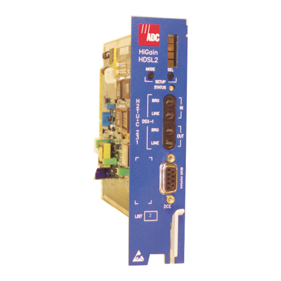
LTPH-UM-1109-01, Issue 1 RONT ANEL Figure 1 shows the H2TU-C-231 List 2 front panel. a list of front-panel display messages, refer to the H2TU-C card-edge connector and craft port, refer to Front-panel display CLEI and ECI barcode label List number... -
Page 12: Front-Panel Description
Normal operation. Fuse alarm. Flashing red HDSL2 acquisition or system alarm. Yellow An H2TU-C-231 Customer Remote Loopback (CREM) or a Network Local Loopback (NLOC) is in effect. Flashing yellow H2TU-C-231 is in an Armed (ARM) state. DSX-1 access jacks Provides non-intrusive bridging jack access to (IN) and from (OUT) the HDSL2 span at the DSX-1 interface. -
Page 13: Front-Panel Display Messages
Signal from customer is looped back to the customer at the H2TU-R. Dual loopback at the H2TU-C. Signal from customer is looped back to the customer at H2TU-C-231. DSX-1 signal is looped back to the network at the H2TU-C. January 9, 2002... - Page 14 The transceivers of the H2TU-C and H2TU-R are trying to establish contact with each other over the HDSL2 loop. The line code that H2TU-C-231 is receiving at its DSX-1 interface, if the DS1 option is set to AUTO. Otherwise, it mimics either of the other two DS1 line code settings, Alternate Mark Inversion (AMI) or Bipolar with 8-Zero Substitution (B8ZS).
-
Page 15: Installation
To comply with the intrabuilding wiring requirements of GR-1089 CORE, Section 4.5.9, the shields of the ABAM-type cables that connect the H2TU-C-231 List 2 DSX-1 output ports to the cross-connect panel must be grounded at both ends. -
Page 16: Verification
Installation ERIFICATION Once the H2TU-C-231 is installed, verify that it is operating properly. To do this, monitor the following: • Status LED (see Figure 1 on page • Status messages reported by the front-panel display (see Verification without an H2TU-R Remote Unit If there is no H2TU-R remote unit installed: Verify that the H2TU-C powers up. -
Page 17: Provisioning
SING THE Setting Options through MODE and SEL To provision the H2TU-C-231 List 2 through the MODE and SEL pushbuttons on the front panel: Press the MODE pushbutton for 1 second and release it. The front-panel display alternately shows the first system parameter and its current setting. -
Page 18: Resetting To Factory Default Values
Provisioning Resetting to Factory Default Values All user options for the H2TU-C-231 List 2 MODE and SEL pushbuttons. To set the user options to their default values: Press the SEL pushbutton for 6 seconds until the following message appears: DFLT NO Press the SEL pushbutton while the DFLT NO message is displayed. -
Page 19: Using A Maintenance Terminal
Connecting to a Maintenance Terminal The craft port on the front panel allows you to connect the H2TU-C-231 to a maintenance terminal (ASCII terminal or PC running a terminal emulation program). Once connected to a maintenance terminal, you can access the maintenance, provisioning, and performance screens. -
Page 20: Logon Screen Menus
Identifies the 100 most recent system events and reports the date and time of occurrence. Config Provides standard configuration options, ADC options, BER tester (BERT), date and time setting, and a reset option (factory settings). Also provides a master clear option that clears all performance, alarm, and event log entries. -
Page 21: Provisioning Tasks
Provides a glossary of terms used in the maintenance screens, a list of navigational keys, and ADC contact information. ROVISIONING ASKS After H2TU-C-231 is successfully installed, perform these basic provisioning tasks. • Set date and time (see “Setting Date and Time”... -
Page 22: Setting Circuit Id Numbers
H2TU-R-402 3.00 0x157C L1-HB2 1.51 0123456789 VAR1JBKEAA 08/28/2001 Circuit and Unit Identifications 09/01/2001 12:30:01 Figure 5. Inventory Screen ENTER January 9, 2002 LTPH-UM-1109-01, Issue 1 ENTER Report Rlogon Help --------------------- H2TU-C System: OK___ ENTER after each entry. H2TU-C-231 List 2... -
Page 23: Configuring The System
Figure 8 on page 16 supported by HiGain HDSL2 units when connected to units from other vendors. ADC options are an extended set of options that are only available when using HiGain HDSL2 units exclusively. For a description of each option... -
Page 24: Config Menu - Standard Options (Defaults Shown)
Figure 7. Config Menu - Standard Options (defaults shown) Monitor Performance Use <Spacebar> to cycle through option settings and <Enter> to activate ID: xxxx—-xxxx—-xxxx--xxxx Figure 8. Config Menu - ADC Options (defaults shown) Event Log Config Inventory +----------------------+ Standard Options ->... -
Page 25: H2Tu-C-231 List 2 Standard Config Menu Options
Only line parameters are considered when monitoring DS1 performance. The H2TU-C-231 and H2TU-R monitor the incoming DS1 bit streams for the B8ZS code. If the H2TU-R detects this code, the H2TU-C enters B8ZS output mode. The H2TU-C reverts back to AMI output mode if no B8ZS codes are received at the H2TU-R input for 5 seconds. -
Page 26: H2Tu-C-231 List 2 Adc Config Menu Options
Enhanced template as defined in Section 6.1.4.2 of ANSI T1/E1.4. Configures the power output levels of the H2TU-C-231 network unit toward the customer to comply with the Default template as defined in Section 6.1.4.2 of ANSI T1/E1.4. - Page 27 LTPH-UM-1109-01, Issue 1 Table 6. H2TU-C-231 List 2 ADC Config Menu Options (Continued) Front Panel ADC Config Menu Display Selection Options Code DS1 BER DBER Threshold “DS1 BER (DBER) Option” on page HDSL2 BER HBER 1E-6 Threshold “HDSL2 BER 1E-7 Threshold (HBER) Option”...
- Page 28 Alarm Pattern (ALMP) Option. To improve HiGain HDSL2 compatibility with the switch-to-protect features used in Digital Loop Carrier (DLC) feeder applications, the H2TU-C-231 List 2 has an Alarm Pattern (ALMP) option that allows you to select either an AIS or LOS DS1 output payload for the following alarms: •...
-
Page 29: Ds1/Dsx-1 24-Hour Pm Threshold
HBER option = 1E-7. Alarm is generated if CRC > 9 Once initiated, the HBER alarm clears when the CRC count drops below the selected threshold. Selecting NONE inhibits this alarm. H2TU-C-231 List 2 Table 7 exceed the counts shown for the 24-hour period between 12:00:00 AM BER. -
Page 30: Config Menu - Set Factory Defaults
Provisioning Resetting to Factory Defaults Resetting the H2TU-C 231 to its original factory settings may cause interruption of service. To reset the H2TU-C-231 List 2 to its original factory defaults: Press to select the Config menu. Use the arrow keys to select Set Factory Defaults, then press... -
Page 31: Clearing The History, Alarm, And Event Log Screens
To clear ALL history, alarm, and event log screens by this method: Press to select the Config screen. Use the arrow keys to select Master Clear. Press to clear all screens. H2TU-C-231 List 2 Event Log Config Inventory +----------------------+ | Standard Options -> | ADC Options ->... -
Page 32: Monitoring System Activity And Performance
-> =18 | LA =25 | | ES =1 | SES=1 | UAS=0 ES =1 | PRM=0 SES=1 UAS=0 |<-RLOS +---+ System status ENTER to make to initiate the loopback or “Testing” beginning on page H2TU-C-231 List 2 Table 8... -
Page 33: Monitor Screen Descriptions
The presence or absence of an alarm condition is indicated on the lower right corner of all screens. System: OK indicates that there are no alarms present; System: Alarm indicates the presence of an alarm. Refer to alarm information. H2TU-C-231 List 2 SPACEBAR Table 8. Monitor Screen Descriptions Table 16 on page 44 for a summary of the HiGain HDSL2 loopback “Using the Performance Screens to View Alarm Data”... -
Page 34: Using The Performance Screens To View Performance Data
ERFORMANCE (Figure 21 on page 33 Figure 22 below and Figure 14 on page 27 is an example of DS1 for descriptions of the kinds of errors Report Rlogon Help SES-P UAS-P PRM-NE PRM-FE H2TU-C System: OK___ H2TU-C-231 List 2... -
Page 35: H2Tu-C Ds1 48-Hour Performance History
Press: (N)ext Page, (P)revious Page, C(l)ear History ----------------------------------------------------------------------------- Use <Space> to cycle through choices and <Enter> to view ID: xxxx—-xxxx--xxxx--xxxx Figure 14. H2TU-R DS1 25-Hour Performance History H2TU-C-231 List 2 Config Inventory H2TU-C DS1 48-Hour History (Page 1 of 4) SES-L... -
Page 36: H2Tu-R Ds1 Current Statistics
Press: C(l)ear Current Statistics Interface : H2TU-C DS1 Statistics : Current 09/01/2001 12:30:01 January 9, 2002 LTPH-UM-1109-01, Issue 1 Figure 16 show statistics for the DS1 Report Rlogon Help H2TU-C System: OK___ Report Rlogon Help H2TU-C System: OK___ H2TU-C-231 List 2... -
Page 37: Acronyms Used On The Ds1 Performance History Screens
(e) Path refers to the total framed payload being transported between two points. (f) Severely Errored Frame—Two or more frame bit errors occurring in a 0.75 ms interval for SF or a 3 ms interval for ESF. H2TU-C-231 List 2 Monitoring System Activity and Performance... -
Page 38: Performance History At The Hdsl2 Interface
: H2TU-C HDSL2 Statistics : 48-Hour History 09/01/2001 12:30:01 January 9, 2002 LTPH-UM-1109-01, Issue 1 Figure 17 Figure 19 Figure 20 on Table 10 on page 32 Report Rlogon Help H2TU-C System: OK___ Report Rlogon Help H2TU-C System: OK___ H2TU-C-231 List 2... -
Page 39: H2Tu-C Hdsl2 25-Hour Performance History
1801 Margin(dB) ------------------------------------------------------------------------------ Use <Space> to cycle through choices and <Enter> to view ID: xxxx--xxxx--xxxx--xxxx Figure 20. H2TU-C HDSL2 Current Statistics H2TU-C-231 List 2 Config Inventory H2TU-C HDSL2 25-Hour History (Page 1 of 9) LOSWS Interface H2TU-C HDSL2 Statistics :... -
Page 40: Using The Performance Screens To View Alarm Data
Severely Errored Seconds Seconds with HDSL2 CRC 50 or LOSW 1 Unavailable Seconds Based on 10 contiguous SES occurrences Loss of Sync Word Second Seconds with LOSW 1 CREENS TO January 9, 2002 LTPH-UM-1109-01, Issue 1 LARM ENTER H2TU-C-231 List 2... -
Page 41: Alarm History At The Ds1 Interface
------------------------------------------------------------------------------ Use <Space> to cycle through choices and <Enter> to view ID: xxxx--xxxx--xxxx--xxxx Figure 22. H2TU-R DS1 Alarm History Screen H2TU-C-231 List 2 (Figure displays the types of alarms reported for both the H2TU-C and H2TU-R. Config Inventory H2TU-C DS1... -
Page 42: Ds1 Alarm Descriptions
LOS (RLOS) or AIS (RAIS) has been received from the CPE. Table 11. DS1 Alarm Descriptions Figure 26 on page BER threshold at 648 events since 12:00:00 AM. January 9, 2002 LTPH-UM-1109-01, Issue 1 42) AIS-CI is sent towards the H2TU-C-231 List 2... -
Page 43: Alarm History At The Hdsl2 Interface
HDSL2 ALARMS at the H2TU-C only SHORT PWR FEED SHRT PWR FEED GND OPEN PWR FEED OPEN H2TU-C-231 List 2 below describes the alarms that are reported at the H2TU-C-231 or H2TU-R. Event Log Config Inventory H2TU-C HDSL2 Alarm History Last 09/01/01 00:45... -
Page 44: Using The System Event Log To Track Events
DS1 LOS Alarm: End DS1 LOS Alarm: Begin DS1 LOS Alarm: End DS1 LOS Alarm: Begin Event Log Reset 09/01/2001 10:06:46 Figure 24. System Event Log January 9, 2002 LTPH-UM-1109-01, Issue 1 VENTS Report Rlogon Help H2TU-C System: OK H2TU-C-231 List 2... -
Page 45: Using The Report Menu
Report menu screen. Monitor Performance Report Type : Please select report type by pressing <Space>, and press <Enter> to generate the report. ID: xxxx—-xxxx—-xxxx--xxxx H2TU-C-231 List 2 to generate. Event Log Config Inventory Full Report then start terminal logging 09/01/2001 12:30:01 Figure 25. -
Page 46: Report Types
• Product information • System configuration • Current performance statistics • Circuit and unit identifications • Product information • System configuration • Circuit and unit identifications • Product information • System event log January 9, 2002 LTPH-UM-1109-01, Issue 1 H2TU-C-231 List 2... -
Page 47: Event Log Entry Messages List
Power Feed Open begins/ends Power Feed Short begins/ends RAI begins/ends LRAI begins/ends (RAI-CI sent from the remote towards the network) H2TU-C-231 List 2 Table 14. Event Log Entry Messages List Event Log Messages January 9, 2002 Monitoring System Activity and Performance... -
Page 48: Testing
LOS is sent towards the network from the H2TU-C. This option prevents the common occurrences of a CPE LOS condition from generating recurring alarms and AIS payloads. Cannot be inhibited. Cannot be inhibited. Cannot be inhibited. Cannot be inhibited. Continued H2TU-C-231 List 2... -
Page 49: Alarm Option For Digital Loop Carrier (Dlc) Feed
(c) Only these alarms assert the System Alarm bus on pins 20 and 21 of the card-edge connector if the ALM option is enabled. (d) When the HDSL2 loop loses sync word (LOSW), a system alarm condition exists. However, since the H2TU-C-231 enters the acquiring mode, the front-panel status LED flashes red, and the ACQ or SIG message displays instead of the ALRM message. -
Page 50: Remote Los And Ais Response
ALMP AMI L January 9, 2002 LTPH-UM-1109-01, Issue 1 Table 6 on AIS to CPE LOS to CPE Loopback to Network Pass on LOS to Network, no alarm report Pass on LOS to Network AIS to Network H2TU-C-231 List 2... -
Page 51: Loopback Operation
Selecting the loopback type from the Monitor Menu when connected to the craft port of the H2TU-C or H2TU-R • Entering the loopback code (exceptions are COLB and RULB) into the test equipment connected to the H2TU-C-231 or H2TU-R. Activate loopback using one of the following: • MODE/SEL pushbuttons •... -
Page 52: Summary Of Higain Hdsl2 Loopback Codes And Activation Methods
MODE and SEL pushbuttons. Use the inband commands to enable or disable the SMJK loopback options. The H2TU-C-231 List 2 system setting is normally enabled to recognize all inband SmartJack loopback commands. -
Page 53: Special Loopback Commands
These additions make A1LB identical to A2LB. A1LB is given a separate identity to allow future DS1/E1 enhancements to be added without affecting A2LB. A5LB differs from A2LB in that A5LB does not block the arming code from exiting the H2TU-C-231 into the network. A1LB and A2LB can be configured to do one of the following: •... -
Page 54: Manual Loopback Session
Press MODE to advance to the next available loopback: • NRE? = NREM • CRE? = CREM • CLO? = CLOC “Setting Options through MODE and SEL” on page January 9, 2002 LTPH-UM-1109-01, Issue 1 Table 16 on H2TU-C-231 List 2... -
Page 55: Loopback Test Procedures
3. Connecting one cable between the two bridging jacks and another between the two LINE jacks splits the IN and OUT and creates metallic loopbacks towards both the DSX-1 and the H2TU-C-231. If separate plugs are inserted into both LINE jacks with the other end disconnected, the BRG jacks can be used to send and receive test patterns towards the DSX-1. -
Page 56: Loopback Modes
HRU-412 H2TU-R 5 IN 7 All ones HRU-412 H2TU-R 3F02 CLOC CLOC CLOC CLOC C742 ‡ 1111100 5-in-7 HRU-412 HRU-412 HRU-412 HRU-412 5 IN 7 5 IN 7 5 IN 7 HRU-412 HRU-412 HRU-412 H2TU-R H2TU-R RULB H2TU-C-231 List 2... -
Page 57: A1Lb, A2Lb, And A5Lb Test Procedures
A tester at the customer premises can activate CLOC, CRG, or CREM loopbacks. All loopbacks shown Table 17 can also be initiated from the H2TU-C-231 front-panel MODE and SEL pushbuttons (see Options through MODE and SEL” on page Table 17. Addressable Repeater Loopback Commands (A1LB, A2LB, A5LB) - Page 58 “Setting the Loopback Time-Out Option” on page (D5D6) is received after activating a loopback, then the automatic timed expiration of the loopback is inhibited. If this Time-Out Override is sent, then the only way to loop the H2TU-C-231 down is to do one of the following: •...
-
Page 59: A3Lb And A4Lb Test Procedures
16-bit loopup command before the timer expires. When this time-out override state exists, the only way to loop the H2TU-C-231 down is to issue one of the three loopdown commands listed in loopback sessions. -
Page 60: Testing With H2Tu-C Bert Generator
January 9, 2002 LTPH-UM-1109-01, Issue 1 ENTER to cycle through the settings. Refer to Report Rlogon Help -> -> : 1 in 7 : AMI : NET only : Continuous H2TU-C System: OK___ 23-1 20-1 pseudo random, 2 H2TU-C-231 List 2... -
Page 61: Testing With H2Tu-R Bert Generator
NREM. The test payload, for the CPE direction, also passes back and forth over the HDSL2 link to the H2TU-C before it is analyzed for errors. H2TU-C-231 List 2 ENERATOR to select the Config menu. -
Page 62: Appendix A - Specifications
0 to 655 feet of ABAM cable +1.5 to -7.5 dB DSX <400 µs Meets MTIE T1.101 requirements 0.2 UI maximum 0.1 UI maximum January 9, 2002 LTPH-UM-1109-01, Issue 1 Dissipation”, and “Maximum Current H2TU-C-231 List 2... -
Page 63: Power Consumption
The -48 Vdc power consumption is the maximum total power that the H2TU-C-231 consumes or draws from the shelf power source. This parameter is needed when the H2TU-C-231 is in a location remote to the CO it is serving. It determines the battery capacity required to maintain an 8-hour standby battery reserve for emergency situations. -
Page 64: Loop Attenuation, Insertion Loss, And Reach
22/0.61 mm 19/0.91 mm (a) Insertion Loss = 1.25 times loop attenuation NSERTION Table 21. HDSL2 Reach Chart Loop Attenuation (dB/kft) 3.88 2.84 2.18 1.54 January 9, 2002 LTPH-UM-1109-01, Issue 1 EACH Maximum Reach per kft (kft) H2TU-C-231 List 2... -
Page 65: H2Tu-C-231 List 2 Card-Edge Connector
Figure 31. H2TU-C-231 List 2 Card-Edge Connector Network Management Control Bus The H2TU-C-231 provides a Network Management Control Bus on pin 46 of the card-edge connector. This allows the various ADC Management System protocols to manage the H2TU-C through the HMU-319 HiGain Management Unit. -
Page 66: Fuse Alarm
The following notes apply to pins 20 and 21: • The H2TU-C-231 Status LED flashes red for the duration of a system alarm condition. • Setting the ALM option to DIS only prevents the system alarm relay pins 20 and 21 from closing for a system alarm event. -
Page 67: Appendix B - Functional Operation
Figure 33. H2TU-C-231 List 2 Block Diagram IMING The low-loop wander (0.5 UI max) of an H2TU-C-231, when used with remote units, allows the circuit to be used in all critical timing applications, including those used to transport Stratum 1 timing. -
Page 68: Appendixc - Compatibility
The HiGain system uses HDSL2 transmission technology as recommended by Bellcore TA-TSY-001210. HiGain HDSL2 complies with GR-63-CORE, TR-TSY-000499, and GR-1089-CORE. The H2TU-C-231 List 2 is compatible with the following DS1 repeater shelves and associated equipment: • HiGain Card Shelf HCS-417 (23” shelf) •... -
Page 69: Appendix D - Product Support
D - P PPENDIX ADC Customer Service Group provides expert pre-sales and post-sales support and training for all its products. Technical support is available 24 hours a day, 7 days a week by contacting the ADC Technical Assistance Center (TAC). Sales Assistance 800.366.3891 extension 73000... -
Page 70: Appendix E - Abbreviations
HiGain Card Shelf HDSL2: High-bit-rate Digital Subscriber Line 2 HiGain HMU: HiGain Management Unit Identification Transmit IOR: Intelligent Office Repeater Intelligent Repeater Loop Attenuation LAIS: Line Alarm Indication Signal LATT: Loop Attenuation Threshold January 9, 2002 LTPH-UM-1109-01, Issue 1 H2TU-C-231 List 2... - Page 71 Power Back Off - Network POTS: Plain Old Telephone Service PRM-FE: Performance Report Messaging - Far End PRM-NE: Performance Report Messaging - Near End PWRF: Line Power Feed H2TU-C-231 List 2 RAI: Remote Alarm Indication RAIS: Remote Alarm Indication Signal RDA: Remote Disconnect Alarm...
- Page 72 Appendix E - Abbreviations LTPH-UM-1109-01, Issue 1 January 9, 2002 H2TU-C-231 List 2...
-
Page 73: Certification And Warranty
ADC during the 90-day warranty period is, at ADC’s option, either (a) return of the price paid or (b) repair or replace of the software. ADC also warrants that, for a period of thirty (30) days from the date of purchase, the media on which software is stored will be free from material defects under normal use. - Page 74 ADC DSL Systems, Inc. 14402 Franklin Avenue Tustin, CA 92780-7013 Tel: 714.832.9922 Fax: 714.832.9924 Technical Assistance Tel: 800.638.0031 Tel: 714.730.3222 Fax: 714.730.2400 : LTPH-UM-1109-01, I OCUMENT SSUE ISO 9001/TL 9000 ´,*r¶7j¨ 1210827 DNV Certification, Inc. REGISTERED FIRM...
Need help?
Do you have a question about the HiGain H2TU-C-231 and is the answer not in the manual?
Questions and answers