
Related Manuals for ADC PG-PLUS PLL-724


Summary of Contents for ADC PG-PLUS PLL-724
- Page 1 PG-P ECHNICAL RACTICE PG-PLUS PLL 724 LIST SYNC MARGIN BYPASS FAULT POTS ISDN 1 POTS/1 ISDN ENTRAL FFICE Model List CLEI Code PLL-724 S9L1AE0A~~ SCP-PLL724-010-04H ECTION...
- Page 2 Information furnished by ADC is believed to be accurate and reliable. In no event shall ADC be liable for any damages resulting from the loss of data, loss of use, or loss of profits and ADC further disclaims any and all liability for indirect, incidental, special, consequential or other similar damages.
- Page 3 • Unpack each container and visually inspect the contents for signs of damage. If the equipment has been damaged in transit, immediately report the extent of damage to the transportation company and to ADC. Order replacement equipment, if necessary. •...
- Page 4 Inspecting Your Shipment SCP-PLL724-010-04H January 6, 2003 PLL-724 List 1...
-
Page 5: Table Of Contents
SCP-PLL724-010-04H ABLE OF ONTENTS Overview ____________________________________________________________________________ 1 Description and Features........................1 Metallic Fallback..........................1 Specifications .............................2 Power Consumption and Heat Dissipation ..................3 Maximum Heat Dissipation....................3 Thermal Loading Limitations ....................4 Maximum Power Consumption...................4 Maximum Current Drain .....................4 Monitoring, History and Diagnostics....................4 Performance Parameters ......................4 Alarm Names and Values ....................5 History ..........................5 LED Descriptions..........................6... - Page 6 SCP-PLL724-010-04H Configuration Submenu........................23 System Options Screen ..................... 24 System Alarm Types Screen ..................... 25 HDSL Alarm Thresholds Screen ..................26 HDSL Alarm Types Screen ....................27 ISDN Options Screen......................29 ISDN Alarm Thresholds Screen ..................30 ISDN Alarm Types Screen ....................31 Save Configuration Screen....................
- Page 7 SCP-PLL724-010-04H IST OF IGURES 1. Typical System Application ..........................1 2. COLU Front Panel LEDs ..........................6 PLL-724 List 1 January 6, 2003...
- Page 8 SCP-PLL724-010-04H January 6, 2003 PLL-724 List 1...
- Page 9 SCP-PLL724-010-04H IST OF ABLES 1. Power Consumption and Heat Dissipation......................3 2. LED Descriptions ............................7 3. Menu Bar Selections............................13 4. System Status..............................14 5. HDSL Alarms Screen ............................21 6. System Options Configuration Fields ......................24 7. System Alarms...............................25 8. HDSL Alarm Thresholds..........................26 9. Alarm Reports ...............................27 10.
- Page 10 SCP-PLL724-010-04H January 6, 2003 PLL-724 List 1...
-
Page 11: Overview
Figure 1. Typical System Application The COLU uses ADC's HDSL technology to provide digital transmission rate without the need for repeaters, loop conditioning, or pair selection. The COLU is an ideal solution to ISDN and POTS deployment over a limited cable plant. -
Page 12: Specifications
Specifications SCP-PLL724-010-04H PECIFICATIONS Power Supply Voltage Safety A2 compliant per GR-1089-CORE Input Voltage -42 Vdc to -56 Vdc HDSL Line Output Voltage + 140 Vdc maximum Output Power 27 W maximum HDSL Line Code 2B1Q HDSL Line Rate 130.6 K symbols/sec; 261.3 K bps HDSL Reach 15.0 kft (4.75 km), 26 AWG;... -
Page 13: Power Consumption And Heat Dissipation
64.0 W per COTS, this limits the number of fully loaded COTS to fourteen per bay with a heat baffle above each COTS. ADC recommends that the number of COTS per bay be limited to six, to allow the flexibility to deploy the widest range of PG-Plus services from each COTS. -
Page 14: Thermal Loading Limitations
Monitoring, History and Diagnostics SCP-PLL724-010-04H Thermal Loading Limitations Thermal loading limitations imposed when using the COLU in a CEV or other enclosures are determined by applying the COLU power parameters to the manufacturer's requirements for each specific housing. Maximum Power Consumption Maximum power consumption is the total power that the COLU consumes or draws from its -48 Vdc COTS power source. -
Page 15: Alarm Names And Values
SCP-PLL724-010-04H Monitoring, History and Diagnostics Alarm Names and Values The COLUs generate alarms for problem conditions on the HDSL transmission facility and at the application interface. From the “HDSL Alarm Thresholds Screen” on page 26, you can set the alarms to the values of Critical, Major, Minor, Not Alarmed, and Not Reported. -
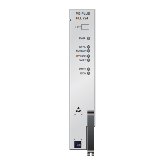
Page 16: Led Descriptions
LED Descriptions SCP-PLL724-010-04H LED D ESCRIPTIONS Table 2 describes the COLU front-panel LEDs in which n equals the POTS line. For further details on the LEDs activities, refer to “Initialization Sequence” on page 8 and the “COLU and RT Fault Indicators” on page 38. PG-PLUS PLL 724 LIST... -
Page 17: Led Descriptions
SCP-PLL724-010-04H LED Descriptions Table 2. LED Descriptions LEDs Mode Description COLU is powered and the dc power provided to the HDSL pair is normal. Flashing One battery feed is missing or a battery feed fuse on the COLU is blown. and FAULT Flashing DC power provided to the HDSL pair is out of normal range. -
Page 18: Installation And Test
Required Tools and Test Equipment SCP-PLL724-010-04H NSTALLATION AND EQUIRED OOLS AND QUIPMENT No tools are required to install the COLU. For testing, the following tools may be utilized: • Telephone test set • ISDN Basic Rate test set • Optional, PSU-795, COTS Continuity Test Card, 150-1695-01 List 1 COLU NSTALLING THE You can install the COLU in any slot except the three positions labeled COMMON, MUX 1, and MUX 2. -
Page 19: Subscriber Drop Tests
SCP-PLL724-010-04H Subscriber Drop Tests UBSCRIBER ESTS You can perform this function in one of two ways: • Initiate a test by applying a test voltage on the Tip at the COLU through an MLT set • With the VT-100 Terminal connected to the PAU or PMU maintenance port, select the Subscriber Drop Test feature from the Test menu. -
Page 20: Logging On
Logging On SCP-PLL724-010-04H OGGING Press the several times to activate the Autobaud feature. Supported baud rates are 1200, 2400, SPACEBAR 4800, 9600, and 38400. The Logon Password screen displays. PG-PLUS Login Screen Enter Password: ____________ Access Key: 062790011146 Type the default password and press to view the PAU or PMU Main Menu bar. - Page 21 SCP-PLL724-010-04H PAU or PMU Main Submenu Screen Identification and Slot Number Current Time Date Provisionable System ID To access a specific COLU when you do not know the slot number, press to view the COTS Summary ENTER screen. Note the slot number of the desired COLU. There may be more than one of the COLU type you are installing.
-
Page 22: Colu Main Menu
COLU Main Menu SCP-PLL724-010-04H Scroll to the Select option and press to access the submenu. ENTER Scroll to the slot number noted above and press ENTER COLU M When you select the COLU from the PAU or PMU Select option, the COLU Main menu displays. You can perform any of the functions listed in Table 3 from this screen. -
Page 23: Navigational Methods
↑ Moves down the submenu selection. Moves the cursor down the screen items. ↓ Returns to the PAU or PMU Main screen. The ADC banner appears briefly and then the Main menu bar CTRL displays. No effect. At COLU screen cycles through choices. -
Page 24: Colu Summary Screen
COLU Main Menu SCP-PLL724-010-04H Table 3. Menu Bar Selections Info Summary of navigational methods. Display registration information to track product manufacturing, configuration, and revision state. COLU Summary Screen This screen details the performance condition of the COLU and RT. Select Main from the menu bar and press to view the COLU Summary screen. -
Page 25: Performance Submenu
SCP-PLL724-010-04H Performance Submenu Table 4. System Status Status Description Active Act bit in the ISDN M-channel is set in the customer direction (towards NT1) as well as network direction (towards LT) Not Active Act bit in the ISDN M-channel is reset in the customer direction or network direction or both. ERFORMANCE UBMENU The Performance submenu provides access to the COLU performance screens. -
Page 26: Hdsl Summary Screen
Performance Submenu SCP-PLL724-010-04H HDSL Summary Screen This screen depicts an HDSL performance summary in terms of the margin and ES count. Use the available options to reset the minimum and maximum margin counts. Select Performance at the menu bar and press to display the submenu. -
Page 27: Hdsl 24-Hour History Screen
SCP-PLL724-010-04H Performance Submenu HDSL 24-Hour History Screen This screen shows twenty-four hours of HDSL performance history. The performance history data displayed includes ES counts, UAS counts, and the validity of the counts. Select Performance at the menu bar and press to display the submenu. -
Page 28: Hdsl 7-Day History Screen
Performance Submenu SCP-PLL724-010-04H HDSL 7-day History Screen Shows seven days of performance history plus the current day's accumulated performance information. The information displayed includes ES counts, UAS counts, and the validity of the counts. Select Performance at the menu bar and press to display the submenu. -
Page 29: Isdn1 Summary Screen
SCP-PLL724-010-04H Performance Submenu ISDN1 Summary Screen Shows all of the stored ISDN performance data for the COLU and the RT. The displayed information includes ES and SES counts for the current hour, the previous hour, the current day and the previous day; and BE counts for the current hour and previous hour. -
Page 30: Isdn 7-Hour History Screen
Alarms Submenu SCP-PLL724-010-04H ISDN 7-Hour History Screen Displays the 7-hour ISDN ES history information for the COLU and the RT. The ES counts for the current hour and the previous hour are also displayed for completeness. This means that the 7-hour history begins with the hour prior to the previous hour. -
Page 31: Hdsl History Screen
SCP-PLL724-010-04H Alarms Submenu HDSL History Screen The HDSL history maintained on the COLU contains a count of the number of times each alarm occurred, the time and date of the first and last occurrence, the provisioned notification type, and the current status. At this screen you view the results of the alarms set at the Configuration “HDSL Alarm Types Screen”... -
Page 32: Isdn History Screen
Alarms Submenu SCP-PLL724-010-04H ISDN History Screen The ISDN History has two pages: the first relates to the COLU, and the second relates to the RT. The information includes the alarm name, the provisional alarm type, the current status of the alarm, the number of times the alarm was reported, the date and time of the first report alarm that of the last reported alarm. -
Page 33: Configuration Submenu
SCP-PLL724-010-04H Configuration Submenu ONFIGURATION UBMENU Provides access to system provisioning screens, and an easy means of resetting all options to factory defaults. Select CONFIG at the menu bar and press to view the submenu. ENTER PLL-724 List 1 January 6, 2003... -
Page 34: System Options Screen
Configuration Submenu SCP-PLL724-010-04H System Options Screen Allows the provisioning of options such as ringing frequency, SDT, HDSL Periodic Power Up, and a System ID. Table 6 shows the configured system data and their factory default value. Select CONFIG at the menu bar and press to display the submenu. -
Page 35: System Alarm Types Screen
SCP-PLL724-010-04H Configuration Submenu System Alarm Types Screen Allows the provisioning of the alarm types of all system alarms including incompatible COLU and RT, No RLU Software, and Input Power Missing. Table 7 shows the System Alarm fields and their default settings. You can view the results of these settings from the “HDSL Summary Screen”... -
Page 36: Hdsl Alarm Thresholds Screen
Configuration Submenu SCP-PLL724-010-04H HDSL Alarm Thresholds Screen This screen is a means to provision the threshold crossing values for the15 minute and 24-hour ES and UAS counts and low margin dB. Table 8 lists the fields of the HDSL Alarm Thresholds and the default factory values. Select CONFIG at the menu bar and press to display the submenu. -
Page 37: Hdsl Alarm Types Screen
SCP-PLL724-010-04H Configuration Submenu HDSL Alarm Types Screen Allows the provisioning of the alarm types for all HDSL Alarms. Table 9 lists the Alarm Reports and Table 10 shows the HDSL Alarms, the possible alarm Types, and the default factory settings. You can view the results of these settings from the “HDSL History Screen”... - Page 38 Configuration Submenu SCP-PLL724-010-04H Table 10. HDSL Alarms Alarm Description Default LOSW COLU cannot receive data over the given HDSL loop. COLU and RT cannot synchronize and is out of service. ES-15 Min. Number of HDSL ES has exceeded the user-configurable threshold to give advance warning that HDSL performance is deteriorating.
-
Page 39: Isdn Options Screen
SCP-PLL724-010-04H Configuration Submenu ISDN Options Screen Provides access to configure the ISDN parameters. The values on the screen are the factory defaults. The Sealing Current fields allows the current to be turned On or Off between the RT and the CPE. The EOC Mode field allows the EOC processing type to be selected. -
Page 40: Isdn Alarm Thresholds Screen
Configuration Submenu SCP-PLL724-010-04H ISDN Alarm Thresholds Screen The fields on this screen are measured hourly and daily: • COLU/RT Customer and Network Hourly ES - An ISDN hourly ES alarm is generated if the accumulated hourly ES count at the COLU/RT reaches or exceeds this threshold value. A single threshold value is used for thresholding errors in the customer or network direction. -
Page 41: Isdn Alarm Types Screen
SCP-PLL724-010-04H Configuration Submenu ISDN Alarm Types Screen Allows the provisioning of the alarm types. Table 11 shows the ISDN Alarms, the possible alarm Types, and the default factory settings. All Alarm fields can be set to Major, Minor, or Not Alarmed. Select CONFIG at the menu bar and press to display the submenu. -
Page 42: Save Configuration Screen
Configuration Submenu SCP-PLL724-010-04H Table 11. ISDN Alarms Defaul Alarm Description ISDN loss of signal condition at COLU and/or RT. LOSW ISDN loss of SYNC word condition at COLU and RT. ISDN hourly and/or daily ES count has reached or exceeded the configured value at COLU and/or ISDN hourly and/or daily SES count has reached or exceeded the value at the COLU and/or RT. -
Page 43: Set Factory Defaults Screen
SCP-PLL724-010-04H Configuration Submenu Press to move up a menu level, or to return to the PAU/PMU Main menu. CTRL Set Factory Defaults Screen Sets all configuration data back to factory default values. Select CONFIG at the menu bar and press to display the submenu. -
Page 44: Test Submenu
Test Submenu SCP-PLL724-010-04H Press to move up a menu level, or to return to the PAU/PMU Main menu. CTRL Save Configuration This does not make the configuration changes permanent. The option must be used to make the changes permanent. UBMENU PG-Plus supports testing of a subscriber drop in two ways. - Page 45 SCP-PLL724-010-04H Test Submenu Performing an SDT on one of the POTS or ISDN channel interrupts service on the line under test. The remaining lines on the PG-Plus system remains in service. Upon tests completion the SDT Results screen displays Subscriber Test, Failure Condition, and Test Status. Tests are performed in the order of display.
-
Page 46: Information Submenu
Information Submenu SCP-PLL724-010-04H NFORMATION UBMENU Provides technical information about the COLU and contact information for ADC Technologies, Inc. Select INFO from the menu and press to view the submenu. ENTER Select either Inventory or Help to view the associated screen. -
Page 47: Help Screen
SCP-PLL724-010-04H Information Submenu Help Screen Provides information on using the screens and menus. The Help screen also lists the ADC Customer Support and Bulletin Board telephone numbers. Press to move up a menu level, or to return to the PAU/PMU CTRL Main menu. -
Page 48: Fault Isolation
COLU and RT Fault Indicators SCP-PLL724-010-04H AULT SOLATION The following sections detail the fault isolation procedures. For sections that indicate a condition such as “distance limitation exceeded”, refer to “Specifications” on page 2 for these values. COLU RT F AULT NDICATORS At the CO, you can use the Craft interface to initiate a SDT to determine the cause of any of the following problems. -
Page 49: Subscriber Reported Faults
SCP-PLL724-010-04H Subscriber Reported Faults Mode Condition Procedure no input power 1 Ground fault condition exists. on-board fuse is blown on 2 Check input power at COTS backplane with COLU removed. COLU 3 If power is present at COTS backplane, replace the COLU. Flashing HDSL line open 1 Check line continuity and resistance. - Page 50 Subscriber Reported Faults SCP-PLL724-010-04H Conditions Causes Procedures Phone does not faulty subscriber station 1 If phone stops ringing when using a butt set at the subscriber location, the instrument subscriber's station internal resistance is too high. Replace phone. stop ringing loop length too long 2 If phone does not stop ringing when using a butt set at the subscriber location, one or both of these conditions exist:...
-
Page 51: Product Support
ADC’s Return Material Authorization (RMA) Department. Call or write ADC’s RMA Department to ask for an RMA number and any additional instructions. Use the telephone number, fax number or email address listed below: •... - Page 52 If there is another reason for returning the equipment, please let us know so we can determine how best to help you. Pack the equipment in a shipping carton. Write ADC’s address and the RMA Number you received from the RMA Department clearly on the outside of the carton and return to: ADC DSL Systems, Inc.
-
Page 53: Fcc Classa Compliance
The FCC requires the user to be notified that any changes or modifications made to this device that are not expressly approved by ADC voids the user's warranty. All wiring external to the product(s) should follow the provisions of the current edition of the National Electrical Code. -
Page 54: Acronyms
Modifications SCP-PLL724-010-04H CRONYMS Alarm Cut-Off American Wire Gauge Bit Error Rate Controlled Environmental Vault Central Office COLU PG-Plus Central Office Line Unit COTS PG-Plus Central Office Terminal Shelf Customer Premises Equipment Critical Errored Seconds Federal Communications Commission HDSL High-Bit-Rate Digital Subscriber Line ISDN Integrated Services Digital Network LCFO... - Page 56 World Headquarters: ADC Telecommunications, Inc. 12501 Whitewater Drive Minnetonka, Minnesota USA 55343 For Technical Assistance: 800.366.3891 ´,So¶0)¨ 1251790...
Need help?
Do you have a question about the PG-PLUS PLL-724 and is the answer not in the manual?
Questions and answers