B meters HYDROCAL-M4 User Manual
Hide thumbs
Also See for HYDROCAL-M4:
- Operating and installation instruction (15 pages) ,
- User manual (20 pages)
Table of Contents
Advertisement
Advertisement
Table of Contents

Related Manuals for B meters HYDROCAL-M4


Summary of Contents for B meters HYDROCAL-M4
- Page 1 v 1.1...
-
Page 2: Table Of Contents
HYDROCAL M4 - User Manual Table of Contents 1. Introduction WARNING PACKAGING CONTENT STORAGE CONDITIONS GENERAL INFORMATION 2. Safety information 3. Installation BEFORE INSTALLATION INSTALLATION ALLOWED INSTALLATION POSITIONS TEMPERATURE SENSOR INSTALLATION 4. Functionality 5. Display and buttons 6. Commissioning PROCEDURE FOR COMMISSIONING 7. -
Page 3: Introduction
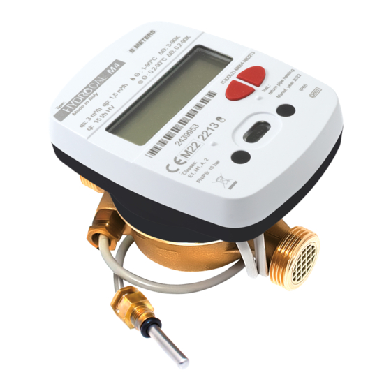
HYDROCAL M4 - User Manual 1. Introduction The HYDROCAL-M4 is a compact thermal energy meter that measures the thermal energy used in heating and cooling systems. The meter allows to measure the thermal energy passing into a hydraulic circuit used for heating and\or for cooling, it also lets the acquisition through external module, of the volume measured by up to 2 device (water, heat, gas, electricity, HCA) equipped with pulse emitter. -
Page 4: Safety Information
HYDROCAL M4 - User Manual 2. Safety information Attention: this symbol highlights the instructions to be followed scrupulously for the correct functioning of the combined heat and cooling meter. Danger: the chapters marked with this symbol contain information that must be followed carefully to avoid dangerous situations. - Page 5 Mount only the newly supplied gaskets (gaskets should not get in the pipeline). Seals provided on site must be fit for purpose and comply with local guidelines and directives. B METERS disclaim all liability for consequential damage resulting from the use of third-party gaskets, such as corrosion of sealing surfaces and threads.
-
Page 6: Installation
HYDROCAL M4 - User Manual 3. Installation The first configuration chosen during installation (supply or return pipe) can’t be modified! BEFORE INSTALLATION Before the thermal energy meter installation make sure that the two ends of the inlet and outlet pipe are perfectly aligned, clean them with the utmost care. -
Page 7: Allowed Installation Positions
HYDROCAL M4 - User Manual ALLOWED INSTALLATION POSITIONS All versions of the thermal energy meter can be installed both horizontally and vertically. For a better performance it is preferable, however, the horizontal installation with the turbine axis perpendicular to the ground and the reading mechanism facing upwards. - Page 8 HYDROCAL M4 - User Manual BALL VALVE INSTALLATION 1. Insert the probe into the threaded nut 2. Insert the closing pin 3. Unscrew the valve closing screw, and place appropriate seals 4. Insert the probe by screwing it on the threaded guide For a correct temperature measurement, the tip of the probe must be in the center of the pipe.
-
Page 9: Functionality
HYDROCAL M4 - User Manual 4. Functionality The HYDROCAL-M4 thermal energy meter is equipped with dedicated sections for the measurement of thermal energy of a heating/cooling circuit and the volume measurement given by the domestic hot and cold-water meters. The meter is suitable for domestic applications with two-pipe systems, in a thermal power plant or any other compatible application. -
Page 10: Commissioning
HYDROCAL M4 - User Manual 6. Commissioning The first configuration chosen during installation (supply or return pipe) can’t be modified! Premise: before a functional tests, the procedures indicated in this paragraph must be performed for completing the physical installation phases including the connections. The device is delivered in sleep mode. -
Page 11: Procedure For Commissioning
HYDROCAL M4 - User Manual User configuration data can be configured via NFC device and NFC app. Below the list of data available: → All averages values (temperatures, flow rates, etc) are saved every hour. → The biweekly and monthly historical data, present in level 6, are saved at each occurrence (default: day 1, end of month). -
Page 12: Level S1: Initialization
HYDROCAL M4 - User Manual LEVEL S1: INITIALIZATION In this level, based on the order, the configuration of the thermal energy meter (installation version and unit of measurement) is already managed. NFC communication it is disabled in this sleep phase. Note: it’s necessary to holding down the T2 button for 3 seconds for the thermal energy meter initialization. -
Page 13: Level 2: Instantaneous Operating Values
HYDROCAL M4 - User Manual 1.4 Volume useful for accounting (cooling) – Cumulative value 1.5 Total accounted volume (heating and cooling) – Absolute value 1.6 Forward accounted volume (heating and cooling) – Cumulative value 1.7 Reverse volume accounted (heating and cooling) – Cumulative value 1.8 Total value (first additional impulse input) –... -
Page 14: Level 3: Settings (Displaying Only)
HYDROCAL M4 - User Manual 2.7 Temperature difference 2.8 CPU temperature (approximately ±3°C accuracy) LEVEL 3: SETTINGS (DISPLAYING ONLY) 3.1 Serial number 3.2 CRC Calculation firmware (legal part) 3.3 Calculation Firmware Version (legal part) 3.4 Radio Communication Firmware Version (Non-Legal Part) 3.5 Radio Stack Firmware Version (Non-Legal Part) 3.6 Installation version (return or supply) - Page 15 HYDROCAL M4 - User Manual 3.10.2 Initial input value - additional pulse input 1 3.10.3 Medium - additional pulse input 1 3.11 Pulse Input 2 (on, off) 3.11.1 Liters/pulse ratio - additional pulse input 2 3.11.2 Initial input value - additional pulse input 2 3.11.3 Medium - additional pulse input 2 3.12 MBUS interface (on, off) 3.12.1 MBUS primary address (heating and cooling)
-
Page 16: Level 4: Storage Day Data
HYDROCAL M4 - User Manual 3.17 Day and month saving (Annual historical data) 3.18 WMBUS mode (AMR, Walk-by, AMR Custom, Off) 3.19 LoRa interface (on, off) 3.20 Display test – All segments on and all segments off (repeat every 2 seconds) LEVEL 4: STORAGE DAY DATA 1-2 4.1 Memory 1 date of storage 4.1.1 Heating –... -
Page 17: Level 5: Counter Data
HYDROCAL M4 - User Manual 4.2.3 Additional first impulse input consumption – cumulative value Memory 2 4.2.4 Consumption according to additional impulse input – cumulative value Memory 2 LEVEL 5: COUNTER DATA 5.1 Total hours of device life (DDDD.HH.MM) 5.2 Total counting hours (DDDD.HH.MM) 5.3 Total counting hours - heating (DDDD.HH.MM) 5.4 Total counting hours - cooling (DDDD.HH.MM) 5.5 Total counting hours with flow and without a... -
Page 18: Level 7: Annual Historical Data
HYDROCAL M4 - User Manual 6.1.4 Accounted impulse input 2 – cumulative value at monthly historical data 6.1.5 Average supply temperature – average value at monthly historical data 6.1.6 Average return temperature – average value at monthly historical data 6.1.7 Average ambient temperature – average value at monthly historical data 6.1.8 Average power (Kw) –... -
Page 19: Level 8: Errors And Anomalies
HYDROCAL M4 - User Manual 7.1.7 Average ambient temperature – average value at annual historical data 7.1.8 Average power (Kw) – average value at annual historical data 7.1.9 Average flow rate (m3/h) – average value at annual historical data LEVEL 8: ERRORS AND ANOMALIES 8.1 Number of active errors 8.2 Displaying Active Errors LEVEL 9: ERROR LOG... -
Page 20: Operating Mode - Radio Activation
HYDROCAL M4 - User Manual 8. Operating mode – Radio activation This section describes the radio communication management implemented. For the WM-Bus interface there is a test mode that can be activated via NFC (only before the passage of +- 5 liters), that allows to verify the correct functioning of the device. -
Page 21: Radio Indicator On Display
HYDROCAL M4 - User Manual RADIO INDICATOR ON DISPLAY During the JOIN to the network procedure, if the LoRaWAN transmission has been activated, the radio symbol will flash quickly on the display (at a period of 1 second) until the device reaches the JOINED state and then remains always active. -
Page 22: Errors And Faults
Reserved Inform Customer Service Reserved Inform Customer Service The error is triggered when the remaining life of the Hydrocal-M4 battery is End of battery life less than 1 year. Permanent error, the icon is shown on display. Failure, short circuit or tampering on supply or return probe(s). On display, in Probe failure level 2, 'Error’... - Page 23 HYDROCAL M4 - User Manual Error Name Description Reserved Inform Customer Service Reserved Inform Customer Service The error is recorded when a sudden reset of date and time is detected. Wrong Real Time Clock Permanent error, the alarm can be reset via NFC or LORA. Supply Measurement out Measurement of the supply probe over the measuring range.
- Page 24 HYDROCAL M4 - User Manual Error Name Description Too frequent pulses The error is triggered when too frequent pulses are detected on C1. 32** Temporary error, resets automatically when the initial condition is restored. Too frequent pulses The error is triggered when too frequent pulses are detected on C2. 33** Temporary error, resets automatically when the initial condition is restored.
-
Page 25: Battery And Replacement Procedures
HYDROCAL M4 - User Manual 10. Battery and replacement procedures The thermal energy meter constantly monitors the status of the battery (maximum life: 10 years*) and signals the imminent discharge by showing the icon on display . Reporting takes place one year before full discharge. *The battery life strongly depends on the working time window, set during the configuration process, and on the environmental conditions. -
Page 26: Thermal Energy Meter - Technical Data
HYDROCAL M4 - User Manual 11. Thermal energy meter - Technical Data Diameter DN15 (1/2") 110 mm 13 mm 72 mm 3/4" DN20 (3/4") 130 mm 17 mm 76 mm 1" Model Hydrocal M4 Power supply Battery-powered Battery type Lithium, 2 x 2.7 Ah, 3.0V Battery life Maximum 10 years Range temperatures use... -
Page 27: Information For The Correct Disposal Of The Product
HYDROCAL M4 - User Manual Counting operating conditions Heating: ΔΘ≥1K (counting enabling conditions) (start) Cooling: ΔΘ≥0.2K Maximum measurable power 650 kW 0,25 Display LCD, 8 digits + icons Units of measurement J, MJ, GJ, KWh, MWh Temperature probes Digital Probe cable length 1.5 m free probe, 1 m internal probe 0,05 Pulse input... -
Page 28: Quick Menu Scheme
14. Quick menu scheme INDEX 1.01 HEAT J, MJ, GJ, kWh, MWh 1.02 COOL J, MJ, GJ, kWh, MWh 1.03 HEAT m³ 1.04 COOL m³ 1.05 ABSOLUTE m³ 1.06 FORWARD m³ 1.07 REVERSE m³ 1.08 IN 1 m³ 1.09 IN 2 m³... - Page 29 INDEX INDEX 4.01 MEMORY DAY 1 4.01.1 HEAT J, MJ, GJ, kWh, MWh 4.01.2 COOL J, MJ, GJ, kWh, MWh 4.01.3 IN 1 Type of pulse 4.01.4 IN 2 Type of pulse INDEX 4.02 MEMORY DAY 2 4.02.1 HEAT J, MJ, GJ, kWh, MWh 4.02.2 COOL J, MJ, GJ, kWh, MWh...
-
Page 30: Attachment "A
HYDROCAL M4 - User Manual Attachment “A” EU Declaration of conformity CE.HYDROCALM4. 2022.04.29 B Meters S.r.l. Via Friuli, 3 I-33050 Gonars (UDINE) Declare under our sole responsibility that the product(s) Dichiariamo sotto la nostra responsabilità che il\i prodotto(i) Hydrocal M4... -
Page 31: Contacts
HYDROCAL M4 - User Manual Contacts B METERS srl Via Friuli, 3 • Gonars 33050 (UD) • ITALY Tel: +39 0432 931415 Tel: +39 0432 1690412 Fax: +39 0432 992661 E-mail (sales/info): info@bmeters.com E-mail (support): ticket@bmeters.com Web: www.bmeters.com...
Need help?
Do you have a question about the HYDROCAL-M4 and is the answer not in the manual?
Questions and answers