Table of Contents
Advertisement
ENG
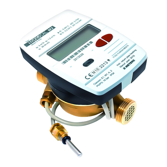
Hydrocal-M3
Heat meter, compact version
USER MANUAL
Premise
The installation must be carried out by qualified personnel only. The manufacturer doesn't assume any
responsibility for improper installation or damages caused by third parties.
Warning
The meter contains potentially dangerous batteries: handle carefully and do not dump in the
environment.
Hydrocal M3 User Manual v1.8
ENG - 1
Advertisement
Table of Contents

Related Manuals for B meters Hydrocal-M3


Summary of Contents for B meters Hydrocal-M3
- Page 1 Hydrocal-M3 Heat meter, compact version USER MANUAL Premise The installation must be carried out by qualified personnel only. The manufacturer doesn’t assume any responsibility for improper installation or damages caused by third parties. Warning The meter contains potentially dangerous batteries: handle carefully and do not dump in the environment.
-
Page 2: Package Contents
INTRODUCTION The model Hydrocal-M3 is a compact heat meter that measures the thermal energy used in the heating and cooling systems. The meter allows to measures the thermal energy passing into a hydraulic circuit used for heating and\or for cooling, it let also the acquisition of the volume measured by up to 2 water meters equipped with pulse emitter. - Page 3 INSTALLATION HYDRAULIC PART BEFORE MOUNTING Before the meter installation make sure that the two ends of the inlet and outlet pipe are perfectly aligned, clean them with the utmost care. Moreover, make sure there is a suitable filter placed at the inlet and that clean and undamaged gaskets are inserted on both sides.
- Page 4 ALLOWED MOUNTING POSITIONS All the versions of the heat meters can be installed both horizontally and vertically. If installed vertically, make sure that the flow direction follows upward direction. For a better performance it is preferable, however, the horizontal installation, with the turbine axis perpendicular to the ground and the reading mechanism facing upwards.
- Page 5 ELECTRONIC UNIT Open the electronic unit by leveraging on the two hooks [1] and remove the cover [2]. For the specific connection instructions, refer to the appropriate sections included in this manual. After the installation, connection, configuration and commissioning, close the cover and apply adhesives sealing.
- Page 6 TEMPERATURE SENSORS INSTALLATION The heat meter is equipped with two PT1000 temperature sensors in accordance with the MID 2004/22/CE and EN1434 approvals. For a proper installation, always proceed in accordance with the guidelines prescribed by law. In the standard version (return pipe mounting position), the return sensor is already built into the brass body.
- Page 7 BALL VALVE INSTALLATION For this kind of installation, first of all it is necessary to insert the temperature sensor in the threaded nut [1] and insert the closing pin [2]. Unscrew the plug screw from the valve and place proper gaskets [3] (included in the package) in order to guarantee a safe installation.
- Page 8 CONNECTIONS AVAILABLES The meter gives the following possibilities of external connections: 2 pulse inputs for connecting of two water meters with pulse emitters (the liter\pulse ratios supported are 0.1 – 0.25 – 1- 2.5 – 10 – 25 – 100 – 250 – 1000) 1 pulse output for the sending of the thermal energy counting (heating only) for the connection to a pulse acquisition system (the Kwh\pulse ratios selectable are 1 –...
- Page 9 M-BUS NETWORK CONNECTION The inputs/outputs “M-Bus” (24 and 25) are dedicated to the meter connection with an M-Bus network cable. For the connection is not necessary to respect the polarity, although it is advisable to keep the same polarity on the entire cable network. Warning: the M-Bus network is using voltage that can damage the device when applied to terminals dedicated to other functions, so be careful when connecting to this interface.
- Page 10 VOLUME METERS C1/C2IN CONNECTION The inputs C1 IN (51, 52, 53) and C2 IN (54, 55, 56) are dedicated to the flowmeters for hot and cold sanitary water. The heat meter is compatible with flowmeters with pulse output OC (open collector) or OA (reed), with pulse value “liters/pulse”...
- Page 11 DISPLAY AND BUTTONS The heat meter is equipped in the front with a liquid crystal display and two buttons (T1 and T2), useful for the configuration of the parameters and for the readings. 1) Eight-digit numeric field; 2) Single-digit numeric index (menu level); 3) Heating data index;...
- Page 12 8) Battery level indicator; 9) Faults indicator; 10) Heating system flowmeter index; 11) Wired M-Bus data index; 11+12) Wireless M-Bus data index (predisposition); 13) Historical data index; 14) Pulse value index (k); 15) Measurement unit index; T1) Level selection button; T2) scroll button within the selected level;...
- Page 13 PROGRAMMING MENU The programming menu is useful for the ordinary programming of the meter and for configured data verification. PROGRAMMING MENU ACCESS To enter the programming menu, press the T1 button and select level 3. Then keep the T2 button pressed for more than 3 seconds.
- Page 14 Confirm the selected parameter by holding the T2 button for more than 3 seconds, thus moving to the next parameter. 3) The third parameter that has be configured is the pulse value "k" of the C2 cold/hot water meter. The value can be selected by using the button T1: 0.1–0.25–1–2.5–10–25–100–250–1000 L/imp Confirm the selected parameter by holding the T2 button for more than 3 seconds, thus moving to the next parameter.
- Page 15 Confirm the selected parameter by holding the T2 button for more than 3 seconds, thus moving to the next parameter. 7) The seventh parameter that has be configured is the primary address of the Wired M-Bus (M-Bus) of the heating data. Select the digit using the T2 button and change the single numbers with the T1 button. Confirm the selected parameter by holding the T2 button for more than 3 seconds, thus moving to the next parameter.
- Page 16 CONSULTING MENU The consulting menu is divided in six levels by a numeric index, always shown in the left-upper part of the display. By pressing the T1 button it is possible to choose the desired level, and by pressing the T2 button it is possible to consult the sublevels of the preset level.
- Page 17 LEVEL 2: ACTUAL ACCOUNTING VALUES 2.1 Actual power 2.2 Actual flow rate 2.3 Inlet flow temperature 2.4 Return flow temperature 2.5 Temperature difference Hydrocal M3 User Manual v1.8 ENG - 17...
- Page 18 LEVEL 3: SETTINGS (DISPLAYING ONLY) 3.1 Serial number 3.2 Firmware version 3.3 Communication Firmware version 3.4 Current Date 3.5 Liters/pulse value for input flow sensor (set during production process) 3.6 Measurement unit (0= Mwh, 1= GJ) 3.8 Liters/pulse value for first input flow meter (C1) 3.9 Starting value first input flow meter (C1) 3.11 Liters/pulse value for second input flow...
- Page 19 3.16 M-Bus Secondary address (Heating) 3.17 M-Bus Primary address (Heating) 3.18 M-Bus Secondary address (Cooling) 3.19 M-Bus Primary address (Cooling) LEVEL 3: SETTINGS (CONFIGURATION) The setting of the parameters can be enabled by pressing T2 for 3 seconds while viewing one of the points of the level 3.
- Page 20 3s.10 Liters/pulse value setting for heating pulse output (Hot out) 3s.12 M-Bus Secondary address setting (Heating) 3s.13 M-Bus Primary address setting (Heating) 3s.14 M-Bus Secondary address setting (Cooling) 3s.15 M-Bus Primary address setting (Cooling) 3s.16 Saving parameters settings and exit 1 = save and exit, 0 = don’t exit Hydrocal M3 User Manual v1.8 ENG - 20...
- Page 21 LEVEL 4: MEMORY DAY DATA 4.1 Memory Day 4.2 Accounted Energy (heating) – cumulative value at memory day 4.3 Accounted Energy (cooling) – cumulative value at memory day 4.4 Accounted Volume (C1) – accounted volume at memory day (optional) 4.5 Accounted Volume (C2) – accounted volume at memory day (optional) Memory day setting: View any of the points in the level 4...
- Page 22 5.3 Historical data storage (up to 26 possible values, saving at the end of the month) 5.3.1 Accounted Energy (heating) – cumulative value at historical memory day 5.3.2 Accounted Energy (cooling) – cumulative value at historical memory day 5.3.3 Accounted Volume (C1) – accounted volume at historical memory day (optional) 5.3.4 Accounted Volume (C2) –...
- Page 23 COMMISSIONING Premise: the procedures explained in this paragraph must be carried out only after the conclusion of the installation phases, the connection procedures and after the testing of the hot/cold water and heating/cooling systems. Warning: once the meter has accounted energy and volumes, some of the settable parameters will no longer be editable.
- Page 24 Here is a list of all the error codes: Error Description Prescription Notes Err101 One of the two temperature sensor Check the integrity and the Return the meter to the cables is cut; connection of the temperature manufacturer. Resettable via At least one cable is disconnected sensor cables.
- Page 25 BATTERY AND REPLACEMENT PROCEDURES The heat meter constantly checks the battery status (average lifetime: 10 years) and signals the imminent discharge showing the icon on the display. The signal will be shown one year before the complete discharge. For the replacement, contact the manufacturer. Warning: the meter is equipped with non-rechargeable batteries, that can be dangerous when used improperly.
- Page 26 Model Hydrocal M3 Power supply Battery supply Battery type Li-SoCl2 Lithium-thionyl chloride, 3,6V 6Ah Battery Life 10 years +1 (depending on the version) Operating temperature range 5 ÷ 55°C Storage temperature range -10 ÷ 55°C Dimensions 112 x 78 x 76.5mm Weights 635g (DN15);...
- Page 27 Hydrocal M3 User Manual v1.8 ENG - 27...
Need help?
Do you have a question about the Hydrocal-M3 and is the answer not in the manual?
Questions and answers