Table of Contents
Advertisement
Available languages
Available languages
Quick Links
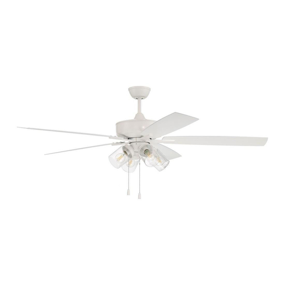
Outdoor Super Pro 60" with Light Kit
Installation Guide
For models:
OS104
OS119
OS211
net weight of fans: 26.94 lb (12.22 kg)--OS104
25.57 lb (11.60 kg)--OS119
26.02 lb (11.80 kg)--OS211
READ THESE INSTRUCTIONS AND
SAVE THEM FOR FUTURE USE
Table of Contents:
Safety Tips. pg. 2
Unpacking Your Fan. pg. 3
Parts Inventory. pg. 3
Installation Preparation. pg. 4
Hanging Bracket Installation. pg. 4
Fan Assembly. pgs. 5 - 6
Wiring. pg. 7
Canopy Assembly. pg. 7
Blade Assembly. pg. 8
Testing Your Fan. pg. 12
Troubleshooting. pg. 13
Parts Replacement. pg. 13
Warranty. pg. 13
page 1
PRINTED IN CHINA
Advertisement
Table of Contents

Related Manuals for Craftmade Outdoor Super Pro OS104


Summary of Contents for Craftmade Outdoor Super Pro OS104
-
Page 1: Table Of Contents
READ THESE INSTRUCTIONS AND SAVE THEM FOR FUTURE USE Outdoor Super Pro 60” with Light Kit Installation Guide Table of Contents: Safety Tips. pg. 2 For models: Unpacking Your Fan. pg. 3 OS104 Parts Inventory. pg. 3 Installation Preparation. pg. 4 OS119 Hanging Bracket Installation. -
Page 2: Safety Tips
(2) this LED light kit must accept any interference received, including interference that may cause undesired operation. Distributed by: Craftmade, 3901 South 20th Avenue, DFW Airport, TX, 75261; 1-800-486-4892 NOTE: The important safety precautions and instructions appearing in the manual are not meant to cover all possible conditions and situations that may occur. -
Page 3: Unpacking Your Fan
1. Unpacking Your Fan. Carefully open the packaging. Remove items from Styrofoam inserts. Remove motor housing and place on carpet or Styrofoam to avoid damage to finish. Do not discard fan carton or Styrofoam inserts should this fan need to be returned for repairs. -
Page 4: Installation Preparation
3. Installation Preparation. blade edge To prevent personal injury and damage, ensure that inches the hanging location allows the blades a clearance 7 feet (76cm) of 7 feet (2.13m) from the floor and 30in. (76cm) (2.13m) from any wall or obstruction. This fan is suitable for room sizes up to 400 square 12ft - 20ft feet (37.2 square meters). -
Page 5: Fan Assembly. Pgs
5. Fan Assembly. stop pin set screw Remove hanging ball from downrod provided by loosening set screw on hanging ball. Lower hanging hanging ball ball and remove stop pin and then slide hanging ball off of the downrod. [Refer to diagram 1.] Loosen yoke set screws and nuts at top of motor diagram 1 housing. - Page 6 5. Fan Assembly. (cont.) Remove electrical tape from electrical wiring and weatherproof thread each of the wires through a different hole hanging in the weatherproof hanging ball cover. Pull ball cover weatherproof hanging ball cover down securely over hanging ball (on downrod). [Refer to electrical wiring diagram 5.] set screw hole...
-
Page 7: Wiring
6. Wiring. WARNING: Turn off circuit breakers to current white supply wire fixture from breaker panel and be sure switch is ground turned to the OFF position. (green or bare) black supply wire CAUTION: Be sure outlet box is properly grounded and that a ground wire (GREEN or Bare) is present. -
Page 8: Blade Assembly
8. Blade Assembly. WARNING: To reduce the risk of serious bodily blade attachment screws/washers injury, DO NOT use power tools to assemble the blades. If screws are overtightened, blades may motor housing crack and break. Time Saver: Washers for blade screws can be set on each blade screw prior to installing blades. -
Page 9: Light Kit Assembly, 4-Light Option
*For Model OS104, follow instructions on this page. *For Model OS119, proceed to instructions on page 10. *For Model OS211, proceed to instructions on page 11. 10. Light Kit Assembly, 4-light Option. Remove 3 screws from outer edge motor of switch housing (at top of light kit housing fitter). -
Page 10: Led Light Kit Assembly, 1-Light Option
*For Model OS119, follow instructions on this page. 11. LED Light Kit Assembly Option. Remove 3 screws from outer edge of switch motor housing (at top of light kit fitter). housing Connect male plug from motor housing to female plug from switch housing, matching up the colors on the male plug with the colors on switch housing the female plug for correct fit. -
Page 11: Light Kit Assembly, 1-Light Option
*For Model OS211, follow instructions on this page. 12. Light Kit Assembly, 1-light Options. Remove 3 screws from outer edge of switch housing (at top of light kit fitter). motor housing Connect male plug from motor housing to female plug from light kit, matching up the colors on the male plug with the colors on the female plug for correct fit. -
Page 12: Testing Your Fan
13. Testing Your Fan. It is recommended that you test fan before finalizing installation. Restore power from circuit box and light switch (if applicable). Test fan speeds with the pull chain on the switch housing. Start at the OFF position (no blade movement). -
Page 13: Troubleshooting
Service at 1-800-486-4892 to arrange for return of fan. 1. Check wall switch to fan. Return fan, shipping prepaid, to Craftmade. We will repair 2. Verify that reverse switch is set completely in or ship you a replacement fan, and we will pay the return either direction. - Page 14 LEER ESTAS INSTRUCCIONES Y GUARDARLAS PARA UTILIZACIÓN FUTURA Outdoor Super Pro 60” con juego de luz Guía de instalación Índice de materias: Sugerencias de seguridad. Pág. 2 Para modelos: Desempaquetado del ventilador. Pág. 3 OS104 Inventario de piezas. Pág. 3 Preparación para la instalación.
- Page 15 Distribuido por: Craftmade, 3901 South 20th Avenue, DFW Airport, TX, 75261; 1-800-486-4892 NOTA: No se debe concluir que las precauciones de seguridad importantes e instrucciones en este manual van a abarcar todas las condiciones y situaciones posibles que puedan ocurrir.
- Page 16 1. Desempaquetado del ventilador. Abrir el empaque cuidadosamente. Sacar los artículos del embalaje. Sacar el motor y ponerlo en una alfombra o en el embalaje para evitar rayar el acabado. Guardar la caja de cartón o el empaquetamiento original en caso de que tenga que mandar el ventilador para alguna reparación.
- Page 17 3. Preparación para la instalación. borde del aspa Para prevenir daño corporal y otros daños, estar seguro 76cm de que el lugar en donde va a colgar el ventilador le permite un espacio libre de 2,13m (7 pies) entre las 2,13m pulg.) puntas de las aspas y el piso y 76cm (30 pulg.) entre las...
- Page 18 5. Ensamblaje del ventilador. perno de tope tornillo Quitar la bola que sirve para colgar del tubo provisto de fijación aflojando el tornillo de fijación de la bola que sirve para bola que sirve colgar. Bajar la bola que sirve para colgar y sacar el perno para colgar de tope y luego quitar la bola que sirve para colgar deslizándola.
- Page 19 5. Ensamblaje del ventilador. (cont.) Quitar la cinta aisladora del cableado y pasar cada cable por un agujero diferente en la cubierta a cubierta a prueba de la intemperie para prueba de la intemperie para la bola que sirve para la bola que sirve colgar.
- Page 20 6. Instalación eléctrica. ADVERTENCIA: Apagar los cortacircuitos en el panel de alambre conductor blanco electricidad que suplen corriente a la caja de salida y toma de tierra asegurarse de que el interruptor de luz esté APAGADO. (verde o pelada) alambre conductor negro PRECAUCIÓN: Asegurarse de que la caja de salida esté...
- Page 21 8. Colocación de las aspas. ADVERTENCIA: Para reducir el riesgo de lesiones tornillo/arandela corporales graves, NO utilizar herramientas eléctricas para fijar el aspa para ensamblar las aspas. Si aprieta demasiado los tornillos, las aspas podrían agrietarse y quebrarse. bastidor del motor Para ahorrar tiempo: Se pueden poner las arandelas en los tornillos que son para las aspas antes de colocar las aspas.
- Page 22 *Para Modelo OS104, seguir las instrucciones de esta página. *Para Modelo OS119, favor de pasar a las instrucciones de la página 10. *Para Modelo OS211, favor de pasar a las instrucciones de la página 11. 10. Instalación del juego de luz, opción de 4 luces. Quitar los 3 tornillos del borde exterior de la caja de encendido (en la parte superior del bastidor...
- Page 23 *Para Modelo OS119, seguir las instrucciones de esta página. 11. Opción de instalación del juego de luz LED. bastidor Quitar los 3 tornillos del borde exterior de la caja del motor de encendido (en la parte superior del conectador para el juego de luz). Conectar el enchufe macho del bastidor del motor al enchufe hembra la caja de encendido, placa de la caja...
- Page 24 *Para Modelo OS211, seguir las instrucciones de esta página. 12. Instalación del juego de luz, opción de 1 sola luz. Quitar los 3 tornillos del borde exterior de la caja de encendido (en la parte superior del conectador para el juego de luz). bastidor del motor Conectar el enchufe macho del bastidor del motor...
- Page 25 13. Verificación del funcionamiento del ventilador. Se le recomienda poner el ventilador a prueba antes de terminar la instalación. Regresar la corriente de electricidad en el cortacircuitos y encender el interruptor de la luz en la pared (si se aplica). Verificar las velocidades del ventilador con la cadena de encendido en la caja de encendido.
- Page 26 Soluciones: debido a defectos en los materiales o trabajo manual. 1. Inspeccionar el interruptor de pared del Comunicarse con el Servicio al cliente de CRAFTMADE al ventilador. 1-800-486-4892 para acordar el reenvío del ventilador. 2. Verificar que el interruptor de reversa del Devolver el ventilador, con los gastos de envío prepagados,...
Need help?
Do you have a question about the Outdoor Super Pro OS104 and is the answer not in the manual?
Questions and answers