
Related Manuals for GLP VOLKSLICHT R-G-B


Summary of Contents for GLP VOLKSLICHT R-G-B
- Page 1 R-G-B from software version 1.08 (Instruction version 1.0) e-mail: service@glp.de Internet: http://www.glp.de...
- Page 2 Notes: German Light Products GmbH (Instruction version 1.0) / from software version 1.08)
-
Page 3: Table Of Contents
Table of content Description of Device....................4 1.1 Safety Instructions .................... 5 Preparation and Installation ................... 6 2.1 Mounting ......................6 2.1.1 Mounting on the Floor (Upright)............. 6 2.1.2 Mounting in hanging Position (Head first)..........7 2.1.3 Mounting in sidewise Position ............... 7 2.2 Secure the Device..................... -
Page 4: Description Of Device
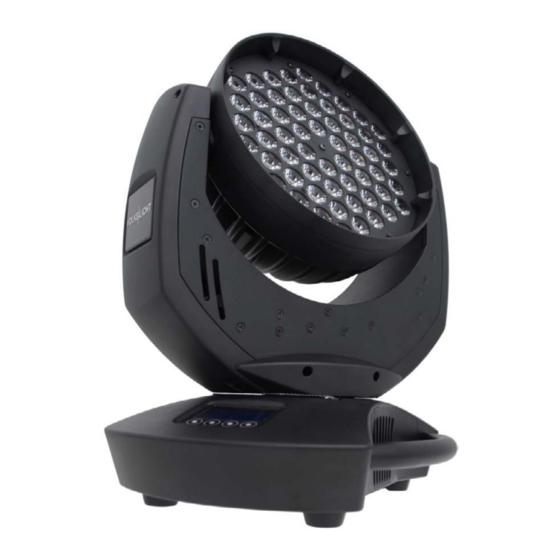
1 Description of Device 1. Moving head (actively and passively cooled) 2. Arm with various cooling vents 3. LCD-Display/Menu (data entry) 4. Base with various connectors and Camlock mounting system 5. Carrying handle. It is also used to attach the safety cable 6. -
Page 5: Safety Instructions
Safety cables or clamps/hooks can increase the risk of an accident. 8. Repair-, maintenance- and installation work shall be done by qualified or GLP certified staff only. You need to pay attention to the common rules of technology that are not explicitly mentioned in this manual. -
Page 6: Preparation And Installation
2 Preparation and Installation 2.1 Mounting T is fully operational whether it hangs or is mounted to the wall. It can also be operated while standing on the floor. Keep a safety distance of 0.5 m towards any easily inflammable materials (decoration etc.). Pay attention to the regulations of: BGV C1 (former VBG 70) and DIN VDE 0711-217. -
Page 7: Mounting In Hanging Position (Head First)
2.1.2 Mounting in hanging Position (Head first) To operate the T in an hanging position, please use a half- coupler (clamp) which is mounted directly onto the bottom side of the system. It is fixed centrically with a M10 thread bolt (max. length 11 mm). 3x M10 (max. -
Page 8: Secure The Device
2.2 Secure the Device Regardless of the mounting method of the T you'll have to use a stipulated safety wire. Therefore you have to pull the safety wire through to two provided holes on the bottom side of the system and connect it with the truss- support. -
Page 9: The Menu Field
The Menu Field You'll find the illuminated control board on the upper side of DMX Start Address the base. It allows you to make all necessary adjustments of the system. The current DMX address will be shown on the top level of the menu. - Page 10 Key code Use the code for entering the calibration menu (for Adjust xxxx authorized persons only) Diagnose Diagnose functions Pan Offset Calibration for Pan-Offset Tilt Offset Calibration for Tilt-Offset Clear Erase EEPROM memory EEPROM Temperatures Indicates the head and base temperature Testmode Performs an automatic self-test Defines whether the last DMX signal is stored or the...
-
Page 11: Dmx Channel Selection (Dmx Protocol)
4 DMX Channel Selection (DMX Protocol) Channel Function Time and Value 1) PAN- 0 .. 660° 0..255 00..FF 0..100 coarse 2) PAN-fine High- Pos ... High- Pos + 2,6° (16 Bit) 0..255 00..FF 0..100 3) Tilt- 0 .. 300° 0..255 00..FF 0..100 coarse... - Page 12 Channel Function Time and Value 0° 08..09 08..09 90° 10..11 0A..0B 180° 12..13 0C..0D 270° 14..15 0E..0F 0° 16..17 11..11 90° 18..19 12..13 180° 20..21 14..15 270° 22..23 16..17 0° 24..25 18..19 90° 26..27 1A..1B 10,4 180° 28..29 1C..1D 11,2 270°...
-
Page 13: Maintaining And Cleaning The T
5 Maintaining and Cleaning the T is a system of very low maintenance. It is only necessary to clean the air in- and outlets as well as the optical LED lenses from time to time. For a safe operation it is absolutely essential that the fixture is kept clean and that dust, dirt and smoke-fluid residues must not built up on or within the fixture. -
Page 14: Technical Specifications
6 Technical Specifications Power supply Power consumption 140 VA (Watt) Power Input ~100-240 V AC, 50-60 Hz (wide range input) Fuse protection Micro-fuse 5x20 mm, T2A Operational Parameters Max. Ambient 45°C (integrated overheating switch) Temperature Mounting Position Any (see chapter mounting) Lighting System - Additive Color mixing LED Type 60x Luxeon Rebel High-power- LEDs... -
Page 15: System Dimensions (In Mm)
7 System dimensions (in mm) German Light Products GmbH (Instruction version 1.0) / from software version 1.08) -
Page 16: Index
8 Index Mounting in hanging Position ......7 Mounting in sidewise Position ......7 BGI 810-3 ............8 Mounting on the Floor ........6 BGV C1............6 Optical parts ..........13 Circumference..........13 Cleaning............13 Pan- Movement..........14 Power Supply ..........8 Danger of BURNING........ - Page 17 German Light Products GmbH (Instruction version 1.0) / from software version 1.08)