
Related Manuals for SKF 40PGA


Summary of Contents for SKF 40PGA
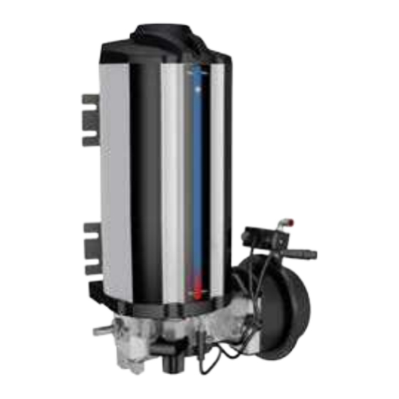
- Page 1 Installation instructions SKF 40PGA Pump Compliant with Directive 2006/42/EC Pneumatic central lubrication system pump Version 02...
-
Page 2: Ec Declaration Of Incorporation Following Machinery Directive 2006/42/Ec, Annex Ii, Part 1 B
EC Declaration of incorporation following machinery directive 2006/42/EC, annex II, part 1 B Manufacturer SKF Lubrication Systems Muurame Teollisuustie 6, FI-40951 Muurame, Finland hereby declares that the partly completed machinery: Designation: Pneumatic lubrication pump for vehicle lubrication systems Type: 40PGA... -
Page 3: Legal Disclosure
○ unauthorised modifications to the © SKF. All rights reserved. product ○ intent or negligence Warranty ○ the use of non-original (non-SKF) spare The instructions do not contain any infor- mation concerning warranties. Warranties parts and guarantees are described in our general Liability for loss or damage resulting from terms and conditions. -
Page 4: Table Of Contents
General description..............16 Modifications to the product ..............9 SKF 40PGA pump .................16 Prohibition of certain activities .............. 9 Single-line SKF MonoFlex lubrication system ........16 Other applicable documents ..............9 System operation ..................17 Notes concerning the type identification plate ........10 1.10... - Page 5 Cleaning agents ..................36 Using a refilling device ................27 12.2 Exterior cleaning ...................36 Bleeding the 40PGA pump unit of air ..........29 12.3 Interior cleaning ..................36 Priming the header piping and bleeding it of air .......29 Shutdown, decommissioning and disposal ......... 37 Lubrication tubes and hoses..............29...
-
Page 6: Explanation Of Symbols, Signs And Abbreviations
Explanation of symbols, signs and abbreviations Explanation of symbols, signs and abbreviations The following symbols are used in the safety Please follow the instructions provided instructions included in this manual to high- especially in the highlighted conditions. light conditions which are potentially harmful Also, be sure that all operators read this to people, materials or the environment. - Page 7 Explanation of symbols, signs and abbreviations Abbreviations and conversion factors regarding °C degrees Celsius °F degrees Fahrenheit approx. approximately Kelvin Ounce i.e. that is Newton fl. oz. fluid ounce etc. et cetera hour inch poss. possibly second pounds per square inch if appl.
-
Page 8: Safety Instructions
1. Safety instructions 1. Safety instructions 1. Safety instructions ○ Safeguards and other protective and 1.2 General behaviour when handling the 1.1 General safety instructions product emergency equipment must not be re- ○ These safety instructions should be read moved, modified, disconnected or other- ○... -
Page 9: Foreseeable Misuse
1. Safety instructions 1. Safety instructions 1.8 Compliance with other applicable 1.4 Forseeable misuse 1.5 Painting of plastic parts prohibited documents Any use differing from that stated in these Painting of any plastic parts or seals of the In addition to these instructions, the fol- instructions is strictly prohibited, particularly described products is expressly prohibited. -
Page 10: Notes Concerning The Type Identification Plate
1. Safety instructions 1. Safety instructions 1.9 Notes concerning the type identifica- 1.10 Notes concerning CE marking 1.11.3 Electrician tion plate Person with appropriate professional edu- The type identification plate indicates the cation, knowledge and experience to detect The product bears the CE marking and con- type designation, order code and other key and avoid electrical hazards. -
Page 11: Emergency Stopping Of The Pump Station
1. Safety instructions 1. Safety instructions diagram and taking the relevant regula- try to carry out maintenance and repair The following must be observed during work at room temperature. tions and the local connection conditions commissioning and operation. into account. ○... -
Page 12: Commissioning And Daily Start-Up
1. Safety instructions 1. Safety instructions ○ Lubricant lines should be primed with ○ Replace illegible or missing warning lubricant prior to installation. This ma- labels without delay. kes it easier to bleed the system of air afterwards. 1.18 Cleaning ○... -
Page 13: Residual Risks
1. Safety instructions 1. Safety instructions 1.19 Residual risks Possible in life- Residual risk Prevention / remedy cycle stage Personal injury / material damage due to Keep unauthorised people away. Make sure no one remains under suspended parts or loads. A, B, C, G, H, K falling of raised parts Lift parts with suitable and tested lifting devices. -
Page 14: Lubricants
2.2 Lubricant selection product may be used. Unsuitable Different lubricants are used in different SKF considers lubricants to be an element of lubricants may lead to product applications. In order to fulfil their tasks, system design. A suitable lubricant is select- failure. -
Page 15: Material Compatibility
(e.g. no "bleeding"). Please contact SKF if you have further ques- tions regarding lubricants. An overview of the lubricants tested by SKF is also available upon request. -
Page 16: General Description
3. General description 3.1 SKF 40PGA pump 3.2 Single-line SKF MonoFlex lubrication system SKF-40PGA is a pneumatic central lubri- cation system pump developed for use in SKF MonoFlex is a single-line centralised vehicles. The main purpose of the pump is to... -
Page 17: System Operation
6. Header tube or hose 2. 24 V DC power cable 7. Mounting rail 3. Control cable 8. B doser 4. Pressurised air supply hose 9. Lubrication tube or hose 5. Pump unit 40PGA - 17 - 16642 Version 02... -
Page 18: Design
4. Design 4. Design 4. Design Figure 2 Main pumping unit components (Figure 2): 1. Body 2. Lubricant reservoir The body assembly includes: 3. Low level switch 4. Solenoid valve 5. Pneumatic actuator 6. M12 branch cable 7. Filling connector 8. -
Page 19: Connections
4. Design 4. Design 4.1 Connections Outputs Table 1. M12 connection • Lubricant outlet, 8 mm Ø M12 pin Cable wire colours Description (Figure 2, item 12), thread: G 1/4" Low limit 24 V DC Brown Inputs White Valve control 24 V DC •... -
Page 20: Technical Data
5. Technical data 5. Technical data 5. Technical data Table 2. Technical data Operating temperature range –30...70 °C Maximum air pressure Normal operating air pressure 4–8 Pressure ratio 16:1 Maximum lubricant pressure Control voltage 24 V DC Power consumption Pump capacity cc per stroke Reservoir volume 1.7, 2, 4, 10... -
Page 21: Dimensions And Weight
5. Technical data 5. Technical data 5.1 Dimensions and weight Table 3. Dimensions and weight Figure 4 SKF-40PGA Pump Width Height Depth Weight dimensions 40PGAP-170 320 7.8 kg 40PGAS-2L 9.6 kg 40PGAA-4L 14.3 kg 40PGAA-10L 325 17.3 kg - 21 -... -
Page 22: Legend
6. Legend 6. Legend Table 4. Legend 40PGA-A-B-C-D Abbreviation Description 40PGA The SKF 40 PGAS pump Plastic reservoir Stainless steel reservoir Aluminium reservoir Lubricant reservoir volume: 1.7 l Lubricant reservoir volume: 2 l Lubricant reservoir volume: 4 l Lubricant reservoir volume: 10 l... -
Page 23: Installation
7. Installation 7. Installation 7. Installation 7.1 General information Figure 5 Only qualified technical personnel may install Installation details and tightening torques for 40PGAS and 40PGAP the products described in these Instructions. ±90° During installation, pay attention to the following: Max. -
Page 24: Minimum Assembly Dimensions
7. Installation 7. Installation 7.2.1 Minimum assembly dimensions Figure 6 Installation details and tightening torques for 40PGAA Make sure there is sufficient space for prod- uct maintenance and possible disassembly by adding a clearance of at least 50 mm to each of the stated dimensions. -
Page 25: Lubrication Line Connection
7. Installation 7. Installation 7.3 Lubrication line connection Observe the following installation instruc- CAUTION tions for safe and smooth operation. ○ Use clean components and primed lubri- Tipping hazard cation lines only. Exercise care when dealing with lu- ○ Lubrication lines shall generally be laid bricants. -
Page 26: System Commissioning
Clean the filling connector fil- NOTICE CAUTION ter regularly and replace when necessary. Do not fill the reservoir of the 40PGA Lubricant pump using a pneumatic filling device due Make sure there are no lubricant to high output and pressure. -
Page 27: Using A Refilling Device
1. Make sure that the area surrounding of Filling device the pumping unit is clean. Impurities in the B ~5° Order code for the SKF filling device: 11600330 system prevent trouble-free operation and cause damage at the lubrication point. 2. Remove the lubricant barrel’s (1) original lid. - Page 28 8. Commissioning 8. Commissioning 12. Disconnect the quick connector from the Figure 8 pumping unit filling connector. Filling connector 13. Fasten the protective cap onto the pumping unit filling connector. 14. Fasten the protective cap (10) onto the filling device quick connector. 15.
-
Page 29: Bleeding The 40Pga Pump Unit Of Air
8. Commissioning 8. Commissioning 8.3 Bleeding the 40PGA pump unit of air 8.5 Lubrication tubes and hoses If there are air bubbles in the pump, the lu- Before installation, prime all lubrication bricant pressure in the header will not reach tubes or hoses using a grease gun. -
Page 30: Commissioning
8. Commissioning 8. Commissioning 8.7 Commissioning To provide safe and proper functioning, a person assigned by the operator must carry out the following inspections. Address any detected deficiencies immediately. Deficiencies may be remedied by an authorised and qualified specialist only. Commissioning checklist Inspections prior to first start-up Electrical connections have been carried out correctly. -
Page 31: System Monitoring And Maintenance
9. Monitoring and maintenance 9. Monitoring and maintenance 9. System monitoring and maintenance Impurities in the lubricant may cause the After cleaning the filter, fill the filter housing pump unit or dosers to malfunction or dam- with grease and place the filter back in its age lubrication points. -
Page 32: Maintenance
9. Monitoring and maintenance 9. Monitoring and maintenance 9.1 Maintenance Faults can be detected and cleared in time only if maintenance is conducted regularly and appropriately. The specific timelines have to be determined, verified at regular intervals and adapted, if necessary, by the operator based on the operating conditions. -
Page 33: Functional Component Testing
10. Functional component testing 10. Functional component testing 10. Functional component testing 10.3 Solenoid valve 40PGA 10.5 Alarm system – reservoir low level switch 10.1 Control centre ST102 (P) Connect the wire harness to the control Check that the control centre receives pow- Press the Extra lubrication button and check centre. -
Page 34: Troubleshooting
Check lubricant viscosity, replace if necessary (NLGI-000...NLGI-1). (in cold conditions). Filling the pump with a manual filling Check and clean the filling inlet filter. device fails (pumping is too heavy) N.A. Contact your Oy SKF Ab representative. - 34 - 16642 Version 02... -
Page 35: Delivery, Returns And Storage
This applies to parts made of plastic and rubber 11.3 Storage (embrittlement) as well as com- SKF products are subject to the following ponents primed with lubricant storage conditions: (ageing) in particular. ○ Store in a closed, dry, dust- and vibrati- on-free place. -
Page 36: Cleaning
• Clean all outer surfaces thoroughly with a cleaned on the inside. Thoroughly remove cleaning damp cloth. To do so, contact the SKF Customer Service agent residues from the product for further instructions. and rinse with clear water. - 36 -... -
Page 37: Shutdown, Decommissioning And Disposal
13. Shutdown, decommissioning and disposal 13. Shutdown, decommissioning and disposal 13. Shutdown, decommissioning and disposal 13.1 Temporary shutdown 13.2 Final decommissioning 13.3 Disposal To temporarily shut down the system: When decommissioning the machine, follow Used equipment filled with ○ Switch off the machine in which the pro- the applicable rules and regulations on dis- lubricant must be decom- posal of lubricants and parts contaminated... -
Page 38: Spare Parts
14. Spare parts 14. Spare parts 14. Spare parts The spare part assemblies specified herein Figure 9. Spare parts should only be used for replacing identical defective assemblies. Using spare parts to modify existing products is not allowed. Table 7. Spare parts Item Description Order code... - Page 39 14. Spare parts 14. Spare parts Table 8. SKF 40PGA accessories Figure 10. SKF ST-102 spare parts Item Description Order code ST-102 CONTROL 11500607 CENTRE ST102P-PS CONTROL 11500608 CENTRE SKF-40PGAS-PS-ST102 11500192 INSTALLATION KIT SKF-40PGAS-PS- ST102P INSTALLATION 11390506 CABLE BETWEEN 40PGAS AND CONTROL...
-
Page 40: Appendix: Control Centre Skf St-102
15. Appendices 15. Appendices Operating and Service Manual SKF ST-102 control centre Compliant with EU Directive 2014/30/EU Control centre for centralised lubrication systems Version 01 - 40 - 16642 Version 02... - Page 41 15. Appendices 15. Appendices EC Declaration of conformity according 2014/30/EU Manufacturer SKF Lubrication Systems Muurame Teollisuustie 6, Fi-40951 Muurame, Finland declares that the product: Description: Control centre for centralised lubrication systems Model/type: ST-102 & ST-102P conforms to the relevant requirements of EMC Directive 2014/30/EU and that the following harmonized standards have been applied: –...
- Page 42 Safety and general instructions in the manual for SKF lubrication systems. Failure to follow these instructions may result in serious injury or damage to the lubrication system or the lubricated equipment.
- Page 43 15. Appendices 15. Appendices When the system is powered on, one of the ton detector is monitored instead of pressure Indicator P is always lit during pressurisa- line indicators is always lit. During pres- levels. Once a pre-set pulse count is reached, tion.
- Page 44 15. Appendices 15. Appendices 4. Operation Table 2. Function button functions 4.1 Function button functions Lubrication Pressing the function button when the lubri- Action program status cation program is calculating the lubrication interval will immediately initiate an extra Lubrication interval Initiate extra lubrication lubrication cycle, bypassing the pre-set lu- Pressurisation...
- Page 45 15. Appendices 15. Appendices 5. ST-102 control centre components Table 3. ST-102 control centre components Figure 3 Symbol Component Function ST-102 control centre components Function button Selecting functions J4: A-E Connector Function button connector Selector switch Program jumper switch Selector switch Program jumper switch Selector switch Program jumper switch...
- Page 46 Closed Open Open surisation time. The pump will stop when the pressure switch acknowledges. 40PGA pump control. The pump will keep the line pressurised through- Open Closed Open out the entire pressurisation time. The pressure switch must acknowl- edge pressurisation (i.e. close) at the end of pressurisation.
- Page 47 15. Appendices 15. Appendices When J9 is closed, only the function button Table 6. Selector switches J4E, Multilube pump control selection can be used for setting lubrication param- Selector switch J4E Meaning eters. Circuit board rotary switches SW1 and SW2 must be set to zero (0). If not, all Closed Multilube pump control is active.
- Page 48 15. Appendices 15. Appendices Table 8. Lubrication cycle settings 6.1 Changing lubrication parameter set- To increase the lubrication cycle setting by tings using the function button one increment, briefly press the function Lubrication cycle Flashes (min) button. When the highest setting is reached, The function button allows users to set the the setting cycle starts from the beginning.
- Page 49 15. Appendices 15. Appendices 6.1.2 Setting the maximum Table 9. Lubrication cycle settings To increase the maximum pressurisation pressurisation time time setting by one increment (see the ta- Maximum pressurisa- Flashes ble), press the function button. When the Set the system's maximum pressurisation tion time (min) highest setting is reached, the setting cycle time to match the minimum time required...
- Page 50 15. Appendices 15. Appendices 6.1.3 Setting the progressive distributor Table 10. Lubrication cycle settings 6.1.4 Exiting the setting mode without pulse count setting saving settings Pulse count Flashes The pulse count setting can only be changed If you do not exit the setting mode by hold- (Number of pulses) if the system is in the progressive lubrication ing the function button for approximately 5...
- Page 51 15. Appendices 15. Appendices 6.2 Changing lubrication parameter Lubrication cycle =lubrication interval (SW 1) Example: The lubrication interval setting settings using rotary switches on the + pressurisation time (SW 2). is set to 10 min and pressurisation time to circuit board 2 minutes.
- Page 52 15. Appendices 15. Appendices 7. Electrical connections Table 12. Electrical connections, Molex connector (X3) Figure 5 Symbol Component Power supply and connections to the lubrication pump (X3) X3:1 X3:12 X3:11 X3:10 X3:9 X3:8 X3:7 X3:2 Supply voltage (+), 12 V DC or 24 V DC X3:3 Supply voltage (–), 0 V DC X3:4...
- Page 53 15. Appendices 15. Appendices 7.1 Extra button input (J5) Table 13. Extra button input functions – contacts open When the contacts of the external switch or Lubrication program stage Function button connected to the J5 connector are Interval Initiate extra lubrication closed, the control system is in the inter- Pressurisation Stop pressurisation...
- Page 54 15. Appendices 15. Appendices 8. Technical data Table 15. Technical data Operating temperature range –30...+80°C Protection class IP30 Dimensions 26 x 60 x 160mm (lxkxs) Operating voltage 12 or 24 VDC (10.5…32 V DC) Power consumption Depends on the lubrication system being controlled, 0...4 A Fuse Self-resetting fuse, 4 A, on the circuit board Pressure switch input (2 pcs) or pulse input from the progressive distributor,...
- Page 55 15. Appendices 15. Appendices Alarms are indicated with LED indicators above the function button (alarms depend on the pumping centre model). Alarms – Pressure alarm, connection for indicator, 5 W max. – Pulse alarm, connection for indicator, 5 W max. –...
- Page 56 Note also that in addition to the application, operating become damaged. temperature, rotation speed and operating environment are also relevant factors in lubri- cant selection. For additional information on grease pumpability, please contact Oy SKF Ab. ATTENTION If the fault cannot be corrected according to these instructions, please contact the sup- plier immediately.
- Page 57 Alarm at the start of pressurisation: MonoFlex or DuoFlex system: – Pressure switch is closed. indicator 1 is flashing. Alarm at the end of pressurisation: See the troubleshooting section in the 40PGA manual. – Pressure switch does not close during pressurisation. Pulse alarm ProFlex system: –...
- Page 58 15. Appendices 15. Appendices 10. Electrical diagram, MonoFlex/40PGA - 58 - 16642 Version 02...
- Page 59 15. Appendices 15. Appendices Installation instructions SKF MonoFlex B doser Doser group for a centralised lubrication system Version 01 - 59 - 16642 Version 02...
- Page 60 Please read and follow the safety instruc- tions included this manual and the Safety and general instructions in the manual for SKF lubrication systems. Failure to follow these instructions may result in serious injury or damage to the lubrication system or the lubricated equipment.
- Page 61 15. Appendices 15. Appendices 4. Operation 5. B doser sizes and adjustment 4.1 B doser 4.2 Unfastening and fastening dosers 5.1 Dosages for B1..B6 dosers During pressurisation, line pressure increas- Use a socket wrench to fasten or unfasten Table 1. B1...B5 doser es and the doser charging valve moves to its dosers.
-
Page 62: Appendix: B Doser
15. Appendices 15. Appendices 5.2 B6 doser adjustment Figure 2 1. Screw off the tube connector at the dos- B doser adjustment table er’s lubrication tube outlet. 2. Open the locking nut (8) on top of the doser. 3. Adjust dosage by turning the adjustment screw (7) located above the locking nut. - Page 63 15. Appendices 15. Appendices 6. Technical data Table 4. Technical data Description Quantity Value Unit Operating temperature range –25...80 °C Maximum operating pressure B1...B5 doser dimensions 15 x 90 x 15 w x h x d B6 doser dimensions 17 x 110 x 17 6.1 Connections Inlets, mounting rail •...
- Page 64 15. Appendices 15. Appendices 7. Designation and codes Example: B2-G1/8-ZN-6 Table 5. Doser designation Doser type Abbreviation Description Doser type: B, doser size: size 2 Doser type: B Doser size 1 Connection between doser and mounting rail: G1/8" Doser size 2 Doser material: galvanised steel Doser size 3 Doser size 4...
- Page 65 15. Appendices 15. Appendices Table 6. B doser codes Doser type Code B1-G1/8-ZN-4 11391000 B2-G1/8-ZN-4 11391050 B3-G1/8-ZN-4 11391100 B4-G1/8-ZN-4 11391150 B5-G1/8-ZN-4 11391200 B6-G1/8-ZN-4 11391250 B1-G1/8-ZN-6 11391300 B2-G1/8-ZN-6 11391350 B3-G1/8-ZN-6 11391400 B4-G1/8-ZN-6 11391450 B5-G1/8-ZN-6 11391500 B6-G1/8-ZN-6 11391255 - 65 - 16642 Version 02...
- Page 66 15. Appendices 15. Appendices Table 7. Mounting rail designation BPLD-XX-YY-U Abbreviation Description Example: BPLD-04-ZN Mounting rail (“Base Plate”) Mounting rail (“Base Plate”) Lubrication system type: LD 0202 Four-slot mounting rail Lubrication system type: LD Two slots on each opposite side 0303 Six-slot mounting rail Mounting rail size: four doser slots...
- Page 67 15. Appendices 15. Appendices Table 8. Mounting rail codes Mounting rail type Order code BPLD-0202-ZN 11392310 BPLD-0303-ZN 11392320 BPLD-04-ZN 11392330 BPLD-06-ZN 11392340 BPLD-08-ZN 11392350 BPLD-0808-ZN 11392360 BPLD-02-S 11392400 BPLD-0303-S 11392750 BPLD-04-S 11392500 BPLD-06-S 11392600 BPLD-0202-ZN-U 12800420 BPLD-0303-ZN-U 12800430 BPLD-04-ZN-U 12800400 BPLD-06-ZN-U 12800410 - 67 -...
- Page 68 Note also that in addition to the application, operating become damaged. temperature, rotation speed and operating environment are also relevant factors in lubri- cant selection. For additional information on grease pumpability, please contact Oy SKF Ab. Table 9. Fault table ATTENTION...
-
Page 69: Notes
FI FI Notes - 69 - 16642 Version 02... - Page 70 Notes - 70 - 16642 Version 02...
- Page 71 FI FI Notes - 71 - 16642 Version 02...
- Page 72 Important information on using SKF products All products delivered by SKF may be used only for their intended purpose as described in this manual and any other instructions provided. Oy SKF Ab Finland Teollisuustie 6 FI-40951 MUURAME Finland Tel: +358 20 7400 800 Fax: +358 20 7400 899 E-mail: skf-lube@skf.com...
Need help?
Do you have a question about the 40PGA and is the answer not in the manual?
Questions and answers