
Related Manuals for SKF 40PGAP-170-24-PS


Summary of Contents for SKF 40PGAP-170-24-PS
- Page 1 Assembly Instructions SKF 40 PGA Pump Date: 30.5.2022 Document no.: 40 PGA Version: 1G Read this manual before installing or commissioning the product and keep it at hand for later reference!
- Page 2 The special technical documents were prepared following Annex VII part B. Upon justifiable request, these special technical documents can be forwarded electronically to the respective national authorities. The authorized company for the compilation of the technical documentation is SKF (U.K.) Limited, 2 Canada Close, Banbury, Oxfordshire, OX16 2RT, GBR. Designation:...
- Page 3 Appendix to Declaration of Incorporation in accordance with 2006/42/EC, Annex II, No. 1 B Description of the essential health and safety requirements according to 2006/42/EC, Annex I, which have been applied and fulfilled. Any essential health and safety requirements not listed here are not relevant to this product Table 1 Appendix to Declaration of Incorporation Valid for: 40PGA lubrication pumps...
-
Page 4: Masthead
The instructions contain no statements regarding the warranty or liability for defects. That information can be found in our General Terms of Payment and Delivery. Training We conduct detailed training in order to enable maximum safety and efficiency. We recommend taking advantage of this training. For further information, contact your authorized SKF dealer or the manufacturer. -
Page 5: Table Of Contents
Solid lubricants ..................................13 3. Overview, design & operation ..............................14 General description ................................14 3.1.1 SKF 40PGA pump ..............................14 3.1.2 Single-line SKF MonoFlex Lubrication system ......................14 System operation ................................. 15 Main components ................................16 Connections..................................17 Pneumatic connection ................................. 17 Electrical connections ................................ - Page 6 7. First start-up ....................................26 Inspections prior to initial start-up ............................26 Inspections during initial start-up ............................26 8. Operation ....................................27 Filling the lubricant reservoir ..............................27 Using a refilling device ................................. 28 Bleeding the 40PGA pump unit of air ........................... 30 Priming the header piping and bleeding it of air ........................
-
Page 7: Safety Alerts, Visual Presentation, And Layout
Safety alerts, visual presentation, and layout While reading these instructions, you will encounter various symbols, illustrations, and text layouts intended to help you navigate and understand the instructions. Their meaning is explained below. Safety alerts: Activities that present specific hazards (to life and limb or possible damage to property) are indicated by safety alerts. Always be sure to follow the instructions given in the safety alerts. -
Page 8: Safety Instructions
" Unauthorized modifications and changes can have an unpredictable effect on safety and operation. Unauthorized modifications and changes are therefore prohibited. Only original SKF spare parts and SKF accessories may be used. " Any unclear points regarding proper condition or correct assembly/operation must be clarified. Operation is prohibited until issues have been clarified. -
Page 9: Persons Authorized To Use The Product
Persons authorized to use the product Operator A person who is qualified by training, knowledge and experience to carry out the functions and activities related to normal operation. This includes avoiding possible hazards that may arise during operation. Specialist in mechanics Person with appropriate professional education, knowledge and experience to detect and avoid the hazards that may arise during transport, installation, start-up, operation, maintenance, repair and disassembly. -
Page 10: Notes On The Type Plate
Notes on the type plate The type plate provides important data such as the type designation, order number, and sometimes regulatory characteristics. To avoid loss of this data in case the type plate becomes illegible, it should be entered in the manual. Fig. -
Page 11: Note On China Rohs Mark
Note on China RoHS mark The China RoHS marking confirms that there is no danger to persons or the environment from the regulated substances contained within the intended period of use (number in the circle) of the product. Emergency shutdown This is done by a course of action to be defined by the operator. -
Page 12: Residual Risks
Residual risks Table 2 Residual risks Residual risk Possible in life cycle Prevention/ remedy Personal injury/ material damage A B C G H K Keep unauthorized persons away. No people may due to falling of raised parts remain under suspended loads. Lift parts with adequate lifting devices. -
Page 13: Lubricants
" The lubricant9s ignition temperature has to be at least 50 Celsius above the maximum surface temperature of the components. Solid lubricants Solid lubricants may only be used after prior consultation with SKF. When solid lubricants are used in lubrication systems, the following rules generally apply: Graphite: "... -
Page 14: Overview, Design & Operation
3.1.1 SKF 40PGA pump The pumping unit is designed for pumping lubricant into central lubrication system. SKF-40PGA is a pneumatic central lubrication system pump developed for use in vehicles. The main purpose of the pump is to feed lubricant into a centralised lubrication system. -
Page 15: System Operation
System operation SKF products operate largely automatically. The activities required during normal operation are limited primarily to checking the pump for damage and proper functioning. The system9s operation is controlled by a control centre, such as the ST-102 (1), which activates the pump at predetermined intervals. -
Page 16: Main Components
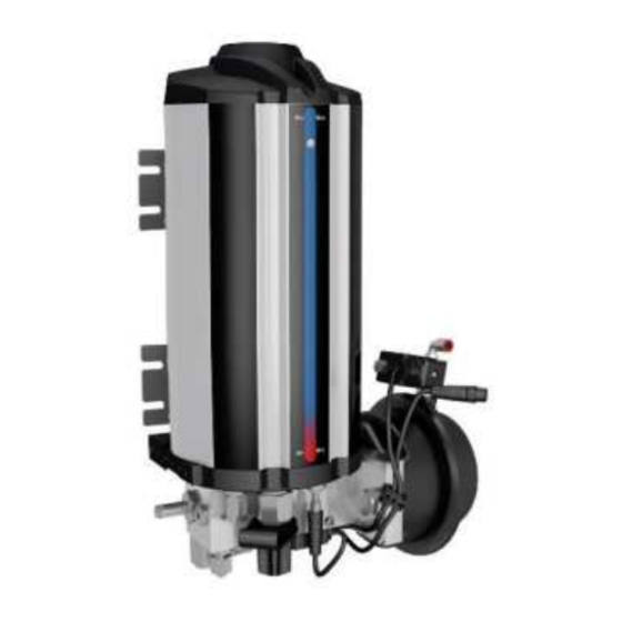
Main components Fig. 3 Main pumping unit components (Figure 3): 1. Body 2. Lubricant reservoir The body assembly includes: 3. Low level switch 4. Solenoid valve 5. Pneumatic actuator 6. M12 branch cable 7. Filling connector 8. Filling filter 9. Pressure switch 10. -
Page 17: Connections
Connections Outputs " Lubricant outlet, Ø 8 mm (Figure 3, item 12), thread: G 1/4" Inputs " Pressurised air inlet connector (Figure 3, item 15), 1 pc, Ø 8 mm nylon tube, barbed insert fitting Electrical connections " Electrical connection, M12 (Figure 3, item 16) Pneumatic connection <... - Page 18 Fig. 4 Table 3 M12 connection M12 pin Cable wire colours Description ¥ Brown Low limit 24V DC ¥ White Valve control 24V DC ¥ Blue Pressure switch 24V DC ¥ Black Protective Earth and Neutral 0V DC Not connected...
-
Page 19: Technical Data
Type identification code Table 5 Type indentification code 40PGA-A-B-C-D Abbreviation Description 40PGA The SKF 40 PGAS pump Plastic reservoir Stainless steel reservoir Aluminium reservoir Lubricant reservoir volume 1.7 l Lubricant reservoir volume 2 l Lubricant reservoir volume 4 l Lubricant reservoir volume 10 l... -
Page 20: Dimensions And Weight
4.2.1 Dimensions and weight Table Dimensions and weight Pump Width Height Depth Weight 40PGAP-170 7.8 kg 40PGAS-2L 9.6 kg 40PGAA-4L 14.3 kg 40PGAA-10L 17.3 kg Fig. 5... -
Page 21: Delivery, Returns, Storage
5. Delivery, returns, storage Delivery After receipt of the shipment, it must be inspected for any shipping damage and for completeness according to the shipping documents. Immediately inform the transport carrier of any shipping damage. The packaging material must be preserved until any discrepancies are resolved. -
Page 22: Storage Period Up To 6 Months
5.5.1 Storage period up to 6 months Filled products can be used without implementing additional measures. 5.5.2 Storage period between 6 and 18 months Pump " Connect the pump to its power source. " Switch on the pump and run it until about 4 ccm of lubricant comes out of every outlet. "... -
Page 23: Installation
6. Installation General information Only qualified technical personnel may install the products described in these Instructions. During assembly, pay attention to the following: " Be careful not to damage other devices during installation. " The product must not be installed within the range of moving parts. "... - Page 24 Fig. 8...
-
Page 25: Lubrication Line Connection
Lubrication line connection < CAUTION Risk of falling Exercise care when dealing with lubricants. Bind and remove spilled or leaked lubricants immediately. < NOTICE Connect lubrication lines in such a way that no forces are transferred to the product (tension free connection). -
Page 26: First Start-Up
7. First start-up In order to warrant safety and function, a person assigned by the operator must carry out the following inspections. Immediately eliminate detected deficiencies. Deficiencies may be remedied by an authorized and qualified specialist only. Checklist Start-up Table 7 Inspections prior to initial start-up YES NO ¥... -
Page 27: Operation
8. Operation Filling the lubricant reservoir < NOTICE Filter of the filling connector has to be cleaned regularly and replaced if necessary. Cleaning and replacing has to be performed when the reservoir is empty. < NOTICE To avoid air bubbles in the reservoir, pump gently when filling the reservoir. <... -
Page 28: Using A Refilling Device
Using a refilling device Fig. 9 1. Make sure that the area surrounding of the pumping unit is clean. Impurities in the system prevent trouble-free operation and cause damage at the lubrication point. 2. Remove the lubricant barrel9s (1) original lid. 3. - Page 29 Fig. 10...
-
Page 30: Bleeding The 40Pga Pump Unit Of Air
Bleeding the 40PGA pump unit of air If there are air bubbles in the pump, the lubricant pressure in the header will not reach sufficient levels. To bleed the pump of air: 1. Disconnect the header tube from the pump outlet. 2. -
Page 31: Maintenance And Repair
9. Maintenance and repair Maintenance Regular and appropriate maintenance is a prerequisite to detect and clear faults in time. The specific time lines have to be determined, verified at regular intervals and adapted, if necessary, by the operator based on the operating conditions. If needed, copy the table for regular maintenance activities. -
Page 32: Cleaning
10. Cleaning Basics Cleaning should be carried out in accordance with the operator's own company rules, and cleaning agents and devices and the personal protective equipment to be used should likewise be selected in accordance with those rules. Only cleaning agents compatible with the materials may be used for cleaning. Completely remove any cleaning agent residue left on the product and rinse with clear water. -
Page 33: Faults, Causes, And Remedies
Lubricant viscosity is too high Check lubricant viscosity, replace if (in cold conditions). necessary (NLGI-000...NLGI-1). Filling the pump with a manual filling device Check and clean the filling inlet filter. fails (pumping is too heavy). Contact your Oy SKF Ab N.A. representative. -
Page 34: Functional Component Testing
Functional component testing 11.2.1 Pumping unit 40PGA Remove the plug or connector closest to the pump from the header tube and press the extra lubrication button. The pump should complete a working stroke and inject a lubricant dose corresponding to its displacement (40 cm³) through the opened connection. -
Page 35: Spare Parts And Accessories
Repair or maintenance work may be carried out only with the spare parts and accessories offered by SKF for the respective product. Spare parts may be used exclusively for replacement of identical defective parts. Modifications with spare parts on existing products are not allowed. -
Page 36: Spare Parts
Spare parts Fig. 12 Table 11 Spare parts Item Description Order code Low level switch 10543528 Solenoid valve 11601420 Pneumatic actuator 11770250 M12 branch cable 11500194 Filling connector 11770460 Filling filter 11770415 Pressure switch 11601477 Discharge valve 11390730 Overfill relief valve 11770490 Visual Level indicator 3 4 l reservoir... -
Page 37: Accessories
Accessories Fig. 13 Table 12 SKF 40 PGA accessories Item Description Order code ST-102 V 2.0 CONTROL CENTRE 11500610 ST-102P-PS CONTROL CENTRE 11500608 SKF-40PGAS-PS-ST102 11500192 INSTALLATION KIT... -
Page 38: Appendix
14. Appendix China RoHS Table Table 13...
Need help?
Do you have a question about the 40PGAP-170-24-PS and is the answer not in the manual?
Questions and answers