Table of Contents
Advertisement
Quick Links
Advertisement
Table of Contents
Troubleshooting

Related Manuals for Furuno FR-10


Summary of Contents for Furuno FR-10
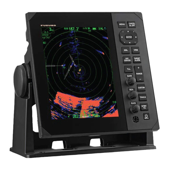
- Page 1 OPERATOR'S MANUAL MARINE RADAR FR-10 FR-12 Model www.furuno.com...
- Page 2 The paper used in this manual is elemental chlorine free. ・FURUNO Authorized Distributor/Dealer 9-52 Ashihara-cho, Nishinomiya, 662-8580, JAPAN A : FEB 2022 Printed in Japan All rights reserved. Pub. No. OME-36870-A (TEHI ) FR-10/12 0 0 0 1 9 9 0 7 4 1 1...
- Page 3 How to discard a used battery Some FURUNO products have a battery(ies). To see if your product has a battery, see the chapter on Maintenance. If a battery is used, tape the + and - terminals of the battery before disposal to pre- vent fire, heat generation caused by short circuit.
- Page 4 Standard Steering Unit Do not place operate the equipment with wet hands. FR-10 0.45 m 0.30 m FR-12 0.65 m 0.40 m Electrical shock can result. Do not place liquid-filled containers Follow the instructions in this manual to on the equipment.
- Page 5 SAFETY INSTRUCTIONS CAUTION The guard zone alarm and and Risk The data presented by this equip- Visualizer are effective aids to ment is intended as a source of anti-collision. navigation information. Using these functions does not relieve The prudent navigator never relies the operator of the responsibility to exclusively on any one source of keep a vigilant watch on his or her...
-
Page 6: Table Of Contents
TABLE OF CONTENTS FOREWORD .........................viii SYSTEM CONFIGURATION ...................x EQUIPMENT LIST ......................xii INSTALLATION & WIRING ...................1-1 1.1 How to Install the Equipment ..................1-1 1.1.1 Display unit..................... 1-1 1.2 Wiring ......................... 1-4 1.3 Input Signal ........................ 1-7 1.3.1 NMEA I/O sentences..................1-7 1.3.2 NMEA2000 PGN .................... - Page 7 TABLE OF CONTENTS 2.19.1 How to measure the bearing with an EBL ............2-21 2.19.2 EBL reference ....................2-22 2.20 How to Measure the Range and Bearing Between Two Targets ......2-22 2.21 How to Select a Pulselength..................2-24 2.22 Target Alarm......................2-25 2.22.1 How to set a target alarm zone ..............2-25 2.22.2 How to stop the audio alarm.................2-26 2.22.3 How to select the alarm type ................2-26 2.22.4 How to sleep a target alarm temporarily............2-27...
- Page 8 TABLE OF CONTENTS 2.39.3 Echo menu ....................2-53 2.39.4 Units menu ....................2-53 2.40 Navigation Data......................2-54 2.41 Waypoint Mark ......................2-54 2.42 How to Send the Target Position and Enter the Origin Mark ........2-55 2.43 Sub Display ......................2-55 ™...
- Page 9 TABLE OF CONTENTS 5.8 Number of Targets to Display..................5-5 5.9 Vector Attributes ......................5-6 5.9.1 What is a vector?....................5-6 5.9.2 Vector time and vector reference ..............5-6 5.10 Past Position Display (target past position) ..............5-6 5.11 CPA/TCPA Alarm .......................5-7 5.12 Proximity Alarm ......................5-7 5.13 Lost Target .........................5-7 5.14 Symbol Color ......................5-8 5.15 How to Ignore Slow Targets ..................5-8...
-
Page 10: Foreword
FOREWORD A Word to the Owner of the FR-10/FR-12 Marine Radar Congratulations on your choice of the FURUNO FR-10/FR-12 Marine Radar. We are confident you will see why the FURUNO name has become synonymous with quality and reliability. Since 1948, FURUNO Electric Company has enjoyed an enviable reputation for innovative and dependable marine electronics equipment. - Page 11 FOREWORD CE declaration With regards to CE declarations, please refer to our website (www.furuno.com) for further infor- mation about RoHS conformity declarations. Note on Chinese font The Chinese font used in this equipment is China Electronics Standardization Institute (CESI) bit- map font.
-
Page 12: System Configuration
Compass , etc.) HDMI External Monitor USB mouse Flash Memory Cable Assembly Cable Assembly Cable Assembly MJ-A3SPF0024-035C (FR-10) MJ-A3SPF0024-035C (FR-10) MJ-A3SPF0024-035C (FR-10) MJ-A3SPF0013A-035C (FR-12) MJ-A3SPF0013A-035C (FR-12) MJ-A3SPF0013A-035C (FR-12) Equipment category Antenna Unit: Exposed to the weather Rectifier Other Equipment: Protected from the weather... - Page 13 NMEA0183 sentence to the external sensors. GPS navigator NMEA2000 Satellite compass Heading sensor NMEA0183 Chart plotter Cable Assembly Cable Assembly Cable Assembly MJ-A3SPF0024-035C (FR-10) MJ-A3SPF0024-035C (FR-10) MJ-A3SPF0024-035C (FR-10) External Buzzer (OP03-21) MJ-A3SPF0013A-035C (FR-12) MJ-A3SPF0013A-035C (FR-12) MJ-A3SPF0013A-035C (FR-12) Equipment category Antenna Unit: Exposed to the weather...
-
Page 14: Equipment List
Power Cable MJ-A3SPF0013A-035C — Installation CP03-40400 000-038-472 Materials Spare Parts SP03-20701 001-613-110 Accessories FP03-13101 001-613-170 Optional supply (FR-10 & FR-12) Name Type Code No. Remarks Chart Kit OP03-266 001-613-190 For FR-12 with chart function- ality only Ethernet HUB HUB-101 000-011-762... - Page 15 EQUIPMENT LIST Name Type Code No. Remarks Cable Assembly FRU-NMEA-PMMFF-010 001-533-060 1 m cable (NMEA2000) FRU-NMEA-PMMFF-020 001-533-070 2 m cable FRU-NMEA-PMMFF-060 001-533-080 6 m cable FRU-NMEA-PFF-010 001-507-010 1 m cable FRU-NMEA-PFF-020 001-507-030 2 m cable FRU-NMEA-PFF-060 001-507-040 6 m cable CB-05PM+05BF-010 000-167-968-10 1 m cable...
- Page 16 EQUIPMENT LIST This page is intentionally left blank.
-
Page 17: Installation & Wiring
INSTALLATION & WIRING How to Install the Equipment 1.1.1 Display unit CAUTION Do not use paint, anti-corrosion products, contact spray or other items containing or- ganic solvents on the equipment. Organic solvents can harm paint and plastic, particularly the connectors. The display unit can be installed on a desktop or flush mounted in a console. - Page 18 1. INSTALLATION & WIRING Desktop mount The hanger is pre-attached to the display unit. For dimensions and required space for maintenance/service, see the outline drawing at the back of this manual. 1. Loosen the knob and remove the hanger. 2. Fix the hanger assembly to a desktop with four self-tapping screws (5 ×20, sup- plied).
- Page 19 1. INSTALLATION & WIRING Flush mount The flush mount kit (available for separate purchase) is required to mount the unit in a console/bulkhead. Select a flat mounting location, and install the unit as shown be- low. Note 1: It is recommended to set up a dedicated breaker when flush mounting the unit, since it will be difficult to disconnect cables after the unit is installed.
-
Page 20: Wiring
1. INSTALLATION & WIRING Wiring All cables are connected at the back of the display unit. NMEA2000 Power (to backbone and external MJ-A3SPF0024-035C (FR-10) NMEA2000 equipment) MJ-A3SPF0013A-053C (FR-12) NMEA0183 ports 1 to 3* *: For external buzzer connection, use port 3. - Page 21 1. INSTALLATION & WIRING Ground CAUTION Do not fail to ground the display unit. If the ground is poor or there is no ground, the radar and other equipment may pick up interference. Grounding guidelines: • The ground wire (local supply) should be 2sq or higher. •...
- Page 22 Check the following points when connecting other display units. • Up to three display units can be connected to a network. Note: When connecting FR-10/12 only: FR main display unit and two sub display units at the maximum. When connecting GP-3700/F: One FR main display unit and one FR sub display unit and GP-3700/F at the maximum.
-
Page 23: Input Signal
1. INSTALLATION & WIRING Input Signal This radar accepts input signals in NMEA format. Three NMEA ports are provided for input signals, and the method of sentence handling is common to all ports. 1.3.1 NMEA I/O sentences NMEA1/NMEA2/NMEA3 Input Sentence •... - Page 24 1. INSTALLATION & WIRING Description 126208 NMEA-Request Group Function NMEA-Command Group Function NMEA-Acknowledge Group Function 126720 Memory Clear Group Function Reset Group Function GMM Message 126992 System Time 126996 Product Information 127250 Vessel Heading 127258 Magnetic Variation 128259 Speed 129025 Position, Rapid Update 129026 COG &...
-
Page 25: Initial Settings
1. INSTALLATION & WIRING Initial Settings Many of the procedures covered in this section require access to the following protect- ed menus. • Units menu • TT Advanced menu • SCX-20 menu • SCX-21 menu • Installation menu • Factory menu To operate the menus, Press the MENU key to show menu window, and then press the MENU key five times while pressing down the CANCEL/HL OFF key. -
Page 26: Installation Menu
1. INSTALLATION & WIRING Language selection from the menu 1. Press the MENU key to show the menu. 2. Access the [Factory] menu. 3. Select [Language], then press the ENTER key. 4. Select your language, then press the ENTER key. Display unit automatically reboots. - Page 27 1. INSTALLATION & WIRING • [Main/Sub Radar]: Set up the FR-10/12 display units as main or sub. See section 1.4.3 for details. • [NMEA LAN Output]: Enable/disable the output of NMEA sentences to the LAN network. Note: When two display units on the same network are set as main display units, turn off either one or the other.
- Page 28 1. INSTALLATION & WIRING line. The target appears "pushed" or "pulled" near the picture center. The range to objects are shown at wrong distances. (1) Target pulled (2) Correct (3) Target pushed outward 1. Transmit on the shortest range, then adjust the gain and the A/C SEA. 2.
- Page 29 • [Total TX Time]: You can set the total TX time as shown below. Note: Send an operator fitness sentence to devices on the same network when something is done at with FR-10/12. 1. Open the [Installation] menu and select [Total TX Time].
-
Page 30: How To Setup Main/Sub Radar Displays
1. INSTALLATION & WIRING 5. Press or to set the value measured at the above step 2. Check that the target appears on the heading line. Note: Increasing the value causes the echo to move counterclockwise. Decreas- ing the value causes the echo to move clockwise. 6. -
Page 31: How To Setup File Menu
1. INSTALLATION & WIRING Radar functions are controlled independently, interlocked or commonly de- pending on selection as Master or Slave (see the table below). Radar Functions Control Master Display Option Slave Display Option AIS function Independent Desired value can be set Desired value can be set Brilliance Echo trails... -
Page 32: How To Change Units Of Measurement
Stores log data to USB memory. to confirm overwriting the existing data appears. Remove USB Memory Prepares to remove attached USB memory from the FR-10/ Popup window will appear. 4. Press the CANCEL/HL OFF key to close the window. 1.4.5... -
Page 33: Advanced Tt Settings
1.4.7 SCX-20 settings The items described in this section assume that your FR-10/12 is connected with an SCX-20 on the same network. If a SCX-20 is not connected, the menu items cannot be changed. For detailed instructions on these settings, see the operator’s manual for the SCX-20. -
Page 34: Scx-21 Settings
1.4.8 SCX-21 settings The items described in this section assume that your FR-10/12 is connected with an SCX-21 on the same network. If a SCX-21 is not connected, the menu items cannot be changed. For detailed instructions on these settings, see the operator’s manual for the SCX-21. - Page 35 1. INSTALLATION & WIRING Terminal Board (local supply) TD-A TD-B External RD-H Buzzer RD-C Cover drain wire with heat-shrink tubing. 12V_P 12V_P 12V_P 12V_M 12V_M 12V_M Attach crimp-on lug (local supply). 1-19...
- Page 36 1. INSTALLATION & WIRING This page is intentionally left blank. 1-20...
-
Page 37: Operation
OPERATION Display Unit Controls Description 1: MENU key. Press to open/close the menu. 2: CANCEL/HL OFF key. During normal operation (press and hold): Hides the heading line. During normal operation (short press): Removes cursor select- ed marks/TT targets or sleep AIS targets. During menu operation: Go up one layer in the menu or cancel the current selection. -
Page 38: How To Turn The Radar On/Off
2. OPERATION How to Turn the Radar On/Off Press the ( /BRILL) key to turn on the radar. To turn off the radar, press and hold down the key until the screen turns off. When you turn on the power, the initializing screen is shown, the preparation screen will appear after about 5 seconds, and the time to warm the magnetron will start count- ing on the screen. -
Page 39: Display Indications
2. OPERATION Display Indications Tuning indicator Trail reference Heading Trail time Zoom indication TX/STBY Sub display North marker Working indicator + TRAIL:T Range 350.0° H D G Target Alarm/Automatic ALM1_IN <SUB> Range ring interval acquisition 1 (2) indications ALM2_IN Offcenter OFFCENT H UP Display mode... -
Page 40: How To Adjust Display Brilliance, Panel Dimmer
Note 1: When the [Display Color] is set to [Custom], the echo color will not change, but the color of the wake will change. Note 2: This menu item is available only for FR-10. -
Page 41: Menu Description
2. OPERATION [Display Color] For setting of the pre-set colors for display. [Echo Color] For setting of the echo color. [Background Color] For setting of the background color. [Character Color] For setting of the character color. [Menu Transparency] For setting of the transparency of the menu box. Set- ting values higher, the menu box gets more transpar- ent. - Page 42 [TT Advanced]: Set up the TT (Target Tracking). [AIS]: Set up the AIS. [Radio]: Set up the radio communication equipment (see chapter 6). [Chart]: Set up the chart (available only for FR-10 with RP board installed, see chapter 7). [System]: - [Initial]: Initial settings.
-
Page 43: Tuning/Channel
2. OPERATION Tuning/Channel For magnetron radars, the radar receiver can be tuned automatically after turning the radar to TX. The default setting is auto-tune. However, if manual tuning is required, proceed as follows: 1. Set the radar in transmit state, then select the maximum range with the RANGE knob. -
Page 44: Display Modes
2. OPERATION Display Modes This radar has the display modes shown below. All modes except head up and stern up require a heading signal. The true motion mode additionally requires position data. Relative Motion (RM) displays • [Head Up] ([H UP]): Heading is at the top of the screen.The picture is redrawn in real time. - Page 45 2. OPERATION 5. Press the MENU key to close the menu. Note 1: The display mode is automatically switched to head up if the heading signal is lost. Note 2: All modes except head up and stern up require a heading signal in AD-10 for- mat or NMEA format.
- Page 46 2. OPERATION True motion mode Your ship and other objects in motion move with their North mark Heading line true courses and speed. All fixed targets, like landmass- es, appear as fixed echoes in ground stabilized TM. When your ship reaches a point that is 75% of the radius of the display, the position is reset.
-
Page 47: How To Select The Range Scale
2. OPERATION How to Select the Range Scale The selected range scale, range ring interval and pulse length are shown at the top left corner on the screen. When an objective target comes closer, reduce the range scale so that the target appears in 50-90% of the display radius. Press the RANGE button to select range. -
Page 48: How To Reduce The Sea Clutter
2. OPERATION manual mode. Select [Yes] with the cursorpad and the Enter key to switch the mode to [Manual]. Select [No] or press the CANCEL/HL OFF key, the screen will disappear with the mode [Auto]. Manual adjustment of gain 1. Rotate the GAIN knob to adjust the gain so that weak noise appears on all of the screen. -
Page 49: How To Reduce The Rain Clutter
2. OPERATION 8. Press the MENU key to close the menu. Note: Rotate the A/C SEA knob while the [Gain Mode] is [Auto], the window shown below appears. Select [Yes] with the cursorpad and the Enter key to switch the mode to [Manual]. Select [No] or press the CANCEL/HL OFF key, the screen will disappear with the mode [Auto]. - Page 50 2. OPERATION If you selected [Auto], go to step 5. For [Manual], go to "Manual adjustment of rain clutter" below. 5. Press the CANCEL/HL OFF key to close the window. 6. Use or to select [Auto Rain] and press ENTER. Note: This item is not available with the DRS4DL+.
-
Page 51: Automatic Adjustments Of Sea And Rain Clutters
2. OPERATION 2.13 Automatic Adjustments of Sea and Rain Clutters When you can not correctly reduce the sea clutter or rain clutter with the related con- trol, turn on the automatic anti-clutter feature. When this feature is turned on, "A/C AUTO" appears at the lower-right corner. Note: Not available with the DRS4DL+ and DRS-NXT series. -
Page 52: Cursor
2. OPERATION 2.14 Cursor The cursor functions to find the range and bearing to a target or the latitude and lon- gitude position of a target. Use the cursorpad to position the cursor and read the cur- sor data. Cursor data appears at the bottom of the screen and by default shows the bearing to the cursor location, followed by the range to the cursor location. -
Page 53: Cursor Type
2. OPERATION 4. Press or to select [RNG/BRG] or [LAT/LON] then press the ENTER key. Note: When [Nav] or [All] is selected on [Data Box] menu, latitude and longitude of cursor is shown above data box. Therefore, the contents of data box is not changed when [Lat/Lon] is selected. -
Page 54: How To Change The Pi Line Orientation
2. OPERATION 2. Press or to select [Others], then press the ENTER key. 3. Press or to select [PI LINES], then press the ENTER key. 4. Press or to select [Off], [2], [3] or [6] then press the ENTER key 5. -
Page 55: Interference Rejector
2. OPERATION 2.17 Interference Rejector Radar interference can occur when your ship is near the radar of another ship that op- erates on the same frequency band with your radar. The interference shows on the screen as many bright dots. The dots can be random or in the shape of dotted lines that run from the center to the edge of the display. -
Page 56: How To Measure The Range With A Vrm
2. OPERATION 2. Press or to select [Brill/Color], then press the ENTER key. 3. Press or to select [Rings Brill], then press the ENTER key. 4. Press or to select an option, then press the ENTER key. [4] is the brightest;... -
Page 57: How To Select Vrm Unit
2. OPERATION Target Cursor (+) VRM 1 VRM 2 The currently active VRM is in a rectangle. VRM 1 range VECTOR:TRU 06:00 5 . 0 4 4 NM VRM 2 range 3 7 . 4 ° R 5 . 0 4 4 NM 0.0°R 0.000NM 2 . -
Page 58: Ebl Reference
2. OPERATION 2. Use the cursorpad to place the EBL through the center of the target. Read the dis- tance at the bottom left corner of the screen. The cursor on the EBL provides an estimate of the range to a target. 3. - Page 59 2. OPERATION 1. Press the EBL key to select [EBL 1]. 2. Use the cursorpad to put the cursor on the center of the target A, then press the ENTER key. 3. Press the EBL key again. The origin of the EBL moves to the cursor position. 4.
-
Page 60: How To Select A Pulselength
2. OPERATION 2.21 How to Select a Pulselength The pulselength in use appears at the upper-left position on the screen. The pulselengths are set to each range scale and custom setup. You can change the pulselength on the 1.5 nm or 3 nm range with the following procedure. Pulselength cannot be changed on other ranges. -
Page 61: Target Alarm
2. OPERATION 2.22 Target Alarm The target alarm looks for targets (ship, landmass, etc.) in the area you set. Audiovisual alarms are released when a target enters (or exits) the alarm area. CAUTION CAUTION · Do not depend on the alarm as the only means to detect possible collision situations. -
Page 62: How To Stop The Audio Alarm
2. OPERATION 2.22.2 How to stop the audio alarm When a target enters (or exits) the target alarm zone, the target flashes and the alarm sounds. The alarm message appears at the bottom of the screen. To stop the audio alarm, press any key. -
Page 63: How To Sleep A Target Alarm Temporarily
2. OPERATION 2.22.4 How to sleep a target alarm temporarily When you do not require a target alarm temporarily, you can sleep the target alarm. The alarm zone remains on the screen, but any targets that enter (or exit) the alarm zone do not trigger the audio and visual alarms. -
Page 64: How To Off-Center The Display
2. OPERATION 2.23 How to Off-center the Display You can off-center your ship position to expand the view field without selecting a larger range scale. The display can be off-centered manually, or automatically according to speed of the ship. Note: Off-centering is not available in the true motion mode. 2.23.1 How to select the off-center mode 1. -
Page 65: Zoom
2. OPERATION 2. Put the cursor on the position where to off-center the display. 3. Press the MENU key to open the menu. 4. Press or to select [Display], then press the ENTER key. 5. Press or to select [Save Offcenter], then press the ENTER key. The message "Complete"... - Page 66 2. OPERATION 4. Select [Zoom], then press the ENTER key. 5. Select [On], then press the ENTER key. The ZOOM indication appears at the upper-left corner on the screen. The zoom window and the zoom cursor also appear (see the illustration on the next page). To quit the zoom, select [Off] instead of [On], then press the ENTER key.
-
Page 67: Echo Stretch
2. OPERATION 4. Press or to select [On], then press the ENTER key. The ZOOM indication appears at the upper-left corner on the screen. The zoom window and the zoom cursor also appear (see the following illustration). To quit the zoom, select [Off] instead of [On], then press the ENTER key. -
Page 68: Target Trails
2. OPERATION 2.26 Target Trails The trails of the radar targets can be shown simulated in afterglow to check target movement. The target trails are selected for either relative or true. True motion trails require a heading signal and position data. 2.26.1 Trail time 1. -
Page 69: Trail Gradation
2. OPERATION True target trails Relative target trails To select the trail mode, do the following: 1. Press the MENU key to open the menu. 2. Press or to select [Trails], then press the ENTER key. 3. Press or to select [Reference], then press the ENTER key. 4. -
Page 70: Trail Level
2. OPERATION 4. Press or to select a color, then press the ENTER key. 5. Press the MENU key to close the menu. 2.26.5 Trail level You can select which target strength to display. 1. Press the MENU key to open the menu. 2. -
Page 71: Own Ship Trail
2. OPERATION [On]: The previous trails are zoomed in or out depending on the changed scale and updated. Copied trail picture Before changing range After changing range Note: If the newly selected range is less than or equal to 1/4 of the previous range, trails are erased. -
Page 72: Custom Setup
2. OPERATION 2.27 Custom Setup 2.27.1 About custom setup When your navigating environment or task changes, you must adjust the radar. In- stead of changing radar settings case by case, you can assign the CUSTOM key to provide best settings for common conditions. There are three default custom setups for the internal computer of the radar. -
Page 73: How To Set Custom Setups
2. OPERATION Menu item Available settings See section [A/C Auto] [Off], [On] section 2.13 [Pulse Length] [Short] or [Long], you can select on 1.5 and 3.0 nm ranges. section 2.21 [Echo Stretch] [Off], [1], [2], [3] section 2.25 [Echo Average] [Off], [1], [2], [Auto] section 2.30 [Int Rejector]... -
Page 74: Target Analyzer
2. OPERATION ™ 2.27.4 Target Analyzer ™ The Target Analyzer function analyzes echoes and assists the operator to determine dangerous targets. This function is particularly useful under heavy rain/snow or where there is surface reflection, which can cause interference and noise. Note: This function is not available when connects the DRS4DL+ and DRS X-Class series radar sensors. -
Page 75: Dynamic Range
2. OPERATION 4. Use or to select a function from the list and press the ENTER key. Below are the available functions. Rings Brill Echo Stretch TCPA Mark Brill Echo Average Proximity HL Brill Int Rejector RV.-Target Char. Brill (Character Brill) Display-Dynamic TT-Display Trail Brill... -
Page 76: Display-Curve
2. OPERATION tensity. The brilliance of sea clutter is reduced to easily identify true targets from the sea clutter. Note 1: Do not use the echo average function under heavy pitching and rolling. You can lose a target. Note 2: This feature requires a heading signal and position data. When either signal becomes lost, echo average is deactivated. -
Page 77: Own Ship And Barge Mark
2. OPERATION 3. Press or to select [Display-Curve], then press the ENTER key. 4. Press or to select [1], [2] or [3] then press the ENTER key. [1]: Reduce weak echoes. [2]: Normal use [3]: Display weaker echoes in stronger color. Strong Echo color strength... -
Page 78: How To Show The Barge Mark
2. OPERATION 5. Press the MENU key to close the menu. The own ship mark appears on the display, scaled according to the length and width entered at installation. 2.32.2 How to show the barge mark The length and breadth of the total barge size can be displayed as a simple rectangle on the radar display. -
Page 79: Watchman
2. OPERATION 9. Select [Barge Arrangement], then press the ENTER key. 10. [Column1(PORT)] is highlighted by the cursor. Press the ENTER key. 1) Set the number of barges in the port column. 2) Set the quantities of barges in the selected column (max: 9), press the ENTER key. -
Page 80: Alerts
2. OPERATION If you press the STBY/TX key before the set time interval comes, the radar goes into transmission. Note 1: If an echo is detected entering the watch alarm area or the automatic acqui- sition area echoes entering the watch alarm area or the automatic acquisition area, the watchman will automatically turn off and the radar will transmit continuously. - Page 81 2. OPERATION 3. Press or to select [Alert Status], then press the ENTER key. 4. Press the CANCEL/HL OFF key to close the window. 5. Press the MENU key to close the menu. See the below for a list of alert status messages and their meanings. Alert category Meaning SIGNAL MISSING*...
- Page 82 2. OPERATION Alert category Meaning TDM2 RX1 board problem. TDM2 RX2 board problem. CH70 RX channel 70 problem. FAIL System failure. UTC sync invalid. Minimum input device lost. GNSS Internal/external GNSS position mismatch. NAV_STATUS NAV status incorrect. HDG_OFFSET Heading sensor offset. SART Active AIS-SART.
-
Page 83: Color Selections
2. OPERATION 2.35 Color Selections 2.35.1 Preset colors This radar is preset with color combinations that provide best viewing in daytime, nighttime and twilight. The table below shows the default color settings Display item Night Twilight Custom Characters Black Green Green Range rings, marks Green... -
Page 84: Echo Area
2. OPERATION 7. Press or to select [Character Color], then press the ENTER key. 8. Press or to select a character color (including range rings and marks), then press the ENTER key. 9. Press the MENU key to close the menu. 2.36 Echo Area You can select the display area from [Normal] or [Full Screen]. -
Page 85: Description Of Initial Sub Menu
Note 1: For initial settings of the SCX-21, connect the SCX-21 to NMEA Port 1 in order to reflect the rules when the FR-10/12 and SCX-21 are connected. Note 2: FR-10/12 does not use the software to forcibly switch the communication speed when the SCX-21 is connected. When connecting the SCX-21, set the commu- nication speed to 38400bps. -
Page 86: Sector Blank
2. OPERATION Mode/Function Simple mode Full mode TX/STBY Left-click on the TX/STBY icon to switch between trans- mitting (TX) and Stand-by (STBY). OFF Center Left-click on the OFF CENTER icon to switch between off and custom. Cannot operate. • Left-click on the target symbol to acquire the tar- get, and right-click to re- lease the target. -
Page 87: Other Menu Items
2. OPERATION 6. Set the start point of the sector, then press the ENTER key. 7. Press or to select [Sect-Blank 1 (or 2) End], then press the ENTER key. 8. Set the end point of the sector, then press the ENTER key. Note 1: You can not set the sector more than 180 degrees. - Page 88 2. OPERATION [Plotter Brill]: Adjust the brilliance of plotter (Setting range: [1] to [4]). [Depth Line Brill]: Adjust the brilliance of depth lines (Setting range: [1] to [4]). [Viewing Position]: Adjust the viewing position between the installation position and user (Setting range: [Left], [Left-Center], [Center], [Right-Center], [Right]). [Display Color]: Adjust the display color (Setting range: [Day], [Night], [Twilight], [Cus- tom]).
-
Page 89: Display Menu
2. OPERATION [Copy To Custom]: Copy the color palette from [System] to [Custom]. 2.39.2 Display menu [Text Display]: You can select on/off for the text indications of the following items on the display. The settings on this function are used when you set [Echo Area] to [Full Screen] on the [Display] menu. -
Page 90: Navigation Data
2. OPERATION 2.40 Navigation Data Navigation data can be displayed at the bottom of the screen. The figure below shows the navigation data display - Cursor latitude position - Cursor longitude position - Time to go to cursor position ゚ ゚... -
Page 91: How To Send The Target Position And Enter The Origin Mark
2. OPERATION 2. Press or to select [Others], then press the ENTER key. 3. Press or to select [WPT Mark], then press the ENTER key. 4. Press or to select [Off] or [On] then press the ENTER key. 5. -
Page 92: How To Use The Risk Visualizer ™ Feature
This unit has a function to observe surrounding vessels and predict danger. By using this function, you will be able to detect danger and take action to avoid a collision as soon as possible. See our WEB site on the URL: https://www.furuno.com/en/technol- ogy/... -
Page 93: Risk Visualizer ™ Display
2. OPERATION Note: This feature does not avoid all hazards. ™ 2.44.1 Risk Visualizer display 1. Press the MENU key to open the menu. 2. Press or to select [Target], then press the ENTER key. 3. Press or to select [Risk Visualizer], then press the ENTER key. The [Risk Visualizer] settings window appears. -
Page 94: Risk Visualizer ™ Alerts
2. OPERATION 6. Press or to select [Display] - [Time], then press the ENTER key. 7. Press or to select the required time, then press the ENTER key. Targets with a potential collision course, within this time-frame, are displayed on- screen as potential risks. -
Page 95: How To Interpret The Radar Display
HOW TO INTERPRET THE RA- DAR DISPLAY General 3.1.1 Minimum and maximum ranges Minimum range The minimum range is defined by the shortest distance at which, using a scale of 0.0625 or 0.125 nm, a target having an echoing area of 10 m is shown separate from the point representing the antenna position. -
Page 96: Radar Resolution
3. HOW TO INTERPRET THE RADAR DISPLAY 3.1.2 Radar resolution The bearing resolution and range resolution are important in radar resolution. Bearing resolution The bearing resolution is the ability of the radar to display the echoes received from two targets at the same range as the separate echoes. The bearing resolution is pro- portional to the antenna length and the wavelength. -
Page 97: Bearing Accuracy
3. HOW TO INTERPRET THE RADAR DISPLAY 3.1.3 Bearing accuracy One of the most important features of the radar is how accurately the bearing of a tar- get can be measured. The accuracy of bearing measurement depends on the narrow- ness of the radar beam. -
Page 98: Sidelobe Echoes
3. HOW TO INTERPRET THE RADAR DISPLAY 3.2.2 Sidelobe echoes When the radar pulse is transmitted, some radiation escapes on each side of the beam, called "sidelobes". If a target is where a target can be detected by the sidelobes as well as the mainlobe, the side echoes can be shown on both sides of the true echo at the same range. -
Page 99: Shadow Sector
3. HOW TO INTERPRET THE RADAR DISPLAY 3.2.4 Shadow sector Funnels, stacks, masts, or derricks near the antenna interrupt the radar beam, and a non-detecting sector can occur. Targets can not be detected within this sector. Radar position Wharf and its echo Wharf and its echo Shadow sector... -
Page 100: General Remarks On Receiving Sart
3. HOW TO INTERPRET THE RADAR DISPLAY 3.3.2 General remarks on receiving SART SART range errors When the SART is at a range greater than approximately 1 nm, the first dot is dis- played at 0.64 nm beyond the true position of the SART. When the range closes so that the fast sweep responses are seen also, the first range echoes are displayed at 150 m beyond the true position. -
Page 101: Tt Operation
TT OPERATION The TT (Target Tracking) feature manually or automatically acquires and tracks (The maximum number of targets depend on the radar sensor). Once a target is acquired, a target is automatically tracked. The target tracking range varies depending on your antenna unit. -
Page 102: Tt Display On/Off
4. TT OPERATION Cursorpad: Select a target to acquire (or cancel the tracking). Select a target to show (or remove) target data (controllable with USB mouse also). TT Display On/Off You can turn the TT display on or off. The system continuously tracks TT regardless of this setting. -
Page 103: Manual Acquisition
4. TT OPERATION Antenna model Single stand-alone configurations Dual stand-alone configurations.* DRS2D/4D/6A/12A/ With AZ and Doppler off: With AZ and Doppler off: 25A-NXT 30 manual; no auto-acquire. 30 manual; no auto-acquire (Only for With AZ on, Doppler off: main display). 30 manual, 30 auto by AZ, 0 by dop- 100 manual;... -
Page 104: How To Stop Tracking A Tt
4. TT OPERATION Note 1: When the DRS4D/6A/12A/25AX-Class or DRS4DL+ is connected, this menu is unavailable. Note 2: When the DRS4D/6A/12A/25A-NXT is connected, COG or SOG is required to use this menu. 1. Press the MENU key to open the menu. 2. -
Page 105: Lost Target
4. TT OPERATION Lost Target When the system detects a lost TT, the au- dio alarm sounds and the alarm message "LOST" appears. The target symbol be- (flashing) comes a flashing circle like the image to the right. When the system detects the target Target before Target after alart generation... -
Page 106: Own Ship Vector
4. TT OPERATION 3. Select [Vector Time], then press the ENTER key. 4. Select time, then press the ENTER key. 5. Select [Vector Reference], then press the ENTER key. 6. Select [Relative] or [True] then press the ENTER key. [Relative]: Other ships’ vectors are displayed relative to your ship. This mode helps find targets on a collision course. -
Page 107: Past Position Display (Target Past Position)
4. TT OPERATION Past Position Display (target past position) This radar can display time-spaced dots (maximum ten dots) that mark the past posi- tions of any TT. You can evaluate actions of a target by the spacing between dots. Be- low are examples of dot spacing and target movement. - Page 108 4. TT OPERATION 2. Press the ENTER key to show the data of the target. Cursor TT selected for data display Data box Vector reference Vector time Target no. ° ° The symbol for the selected TT is displayed at two-times normal size. To remove the data of a target from a data box, put the cursor on the corresponding target symbol, then press the CANCEL HL OFF key or USB mouse.
-
Page 109: Cpa/Tcpa Alarm
4. TT OPERATION 4.11 CPA/TCPA Alarm Set CPA (Closest Point of Approach) alarm range and TCPA (predicted Time to CPA) alarm time to alert you when targets are on a collision course. When CPA and TCPA of any TT become less than the preset CPA and TCPA alarm settings, the audio alarm sounds. -
Page 110: Proximity Alarm
4. TT OPERATION 4.12 Proximity Alarm The proximity alarm alerts you when a TT is within the range you set. (The setting is commonly shared between TT and AIS. See section 5.12.)The audio alarm sounds and the alarm message "PROXIMITY" appears. The target symbol changes to a dan- gerous target symbol and flashes with its vector. -
Page 111: Ais Operation
AIS OPERATION Connected to the FURUNO AIS Transponders FA-170, FA-150, FA-100, FA-50, or the AIS Receiver FA-30, the FR-10/FR-12 can show the name, position and other naviga- tion data of the nearest AIS transponder-equipped ships. This radar accepts position data fixed by WGS-84 geodetic datum. Set the datum to WGS-84 on the GNSS navigator connected to this radar, if this radar is connected to the FURUNO GNSS equipment. -
Page 112: Ais Symbols
5. AIS OPERATION AIS Symbols When the AIS is turned on, AIS targets are displayed with AIS symbol as below. Target type Symbol Description Sleeping target Sleeping target Activated target Activated target. Heading line and ROT are shown. Ground tracking speed and course are shown with vector. -
Page 113: Activating, Sleeping Targets
5. AIS OPERATION Activating, Sleeping Targets When you change a sleeping target to an activated target, a vector shows the course and speed of that target. You can easily judge the target movement by the length and pointing direction of the vector. SOG (Speed Over Ground) and COG (Course over Ground) vector (Rate of Turn) -
Page 114: Ais Target Data
5. AIS OPERATION AIS Target Data You can show AIS target data at the bottom of the screen. Press or to select [Dis- play]-[Data Box], then press [Target] (AIS data) or [All] (AIS data + nav data) position. 1. -
Page 115: Display Range
5. AIS OPERATION 5. Press the MENU key to close the menu. Display Range You can set the AIS system to show only those AIS targets within the range you set. The setting range differs depending on the connected radar sensor. Actual range de- pends on the AIS Transponder. -
Page 116: Vector Attributes
5. AIS OPERATION Vector Attributes 5.9.1 What is a vector? A vector is a line extending from a tracked target. A vector shows speed and course of the target. The top of a vector shows estimated position of the target after the se- lected vector time elapses. -
Page 117: Cpa/Tcpa Alarm
5. AIS OPERATION 7. Select time interval, then press the ENTER key. 8. Press the MENU key to close the menu. 5.11 CPA/TCPA Alarm Set CPA (Closest Point of Approach) alarm range and TCPA (predicted Time to CPA) alarm time to alert you when targets are on a collision course. When CPA and TCPA of any AIS target (including a sleeping target) become less than the preset CPA and TCPA alarm settings, the audio alarm sounds. -
Page 118: Symbol Color
5. AIS OPERATION * The interval at which AIS data is sent depends on speed of the AIS transponder. For detailed information, refer to the Operator's Manual for the AIS transponder. Lost AIS targets are automatically removed from the display one minute after they are determined as lost. -
Page 119: Radio Operation
RADIO OPERATION If the FURUNO DSB transceiver DR-100 (or DM-200) is connected to this radar, up to 51 ship tracks (10 previous tracks per ship) can be shown. Note: The DR-100 and DM-200 is available in Japan only. Radio Display On/Off You can turn the Radio display on or off by below procedure. -
Page 120: Past Position Display
6. RADIO OPERATION 3. Select [Color], then press the ENTER key. 4. Select the color, then press the ENTER key. 5. Press the MENU key to close the menu. Note: Symbols can not be shown in the same color as the background color. Past Position Display You can select the number of past position dots to display. -
Page 121: Target Marks Erase
6. RADIO OPERATION 3. Select [Past Posn Interval], then press the ENTER key. 4. Select the time interval, then press the ENTER key. 5. Press the ENTER key. 6. Press the MENU key to close the menu. Target Marks Erase Other ship’s trail shown on the display can be erased. - Page 122 6. RADIO OPERATION This page is intentionally left blank.
-
Page 123: Chart Overlay
CHART OVERLAY Chart data can be overlayed by installing RP board on the FR-12. Chart Menu Chart display can be switched [On] and [Off] with the following procedures. 1. Press the MENU key to open the menu. 2. Select [Chart], then press the ENTER key. 3. -
Page 124: Chart Type
7. CHART OVERLAY 4. Select [Off], [1], [2] or [3] then press the ENTER key. The value is higher, the more the landmass is emphasized. 5. Press the MENU key to close the menu. Chart Type Select the chart type with below procedure. 1. -
Page 125: Chart Setting
7. CHART OVERLAY Chart Setting You can select which item to show on the chart and which chart color to change on the [Chart Settings] menu. 1. Press the MENU key to open the menu. 2. Select [Chart], then press the ENTER key. 3. -
Page 126: Depth Line Range
7. CHART OVERLAY 7. Press the MENU key to close the menu Depth Line Range Up to 4 depth contour lines can be added to the selected range with the following pro- cedures. 1. Press the MENU key to open the menu. 2. -
Page 127: L/L Grid
7. CHART OVERLAY 1. Press the MENU key to open the menu. 2. Select [Chart], then press the ENTER key. 3. Select [Chart Align], then press the ENTER key. Show the radar image on the screen to close the menu. 4. -
Page 128: Display Ext Marks
7. CHART OVERLAY 7.10 Display Ext Marks When the GP-3700/F is connected, external marks can be shown. 1. Press the MENU key to open the menu. 2. Use or to select [Chart], then press the ENTER key. 3. Select [Display Ext Marks], then press the ENTER key. 4. -
Page 129: Maintenance, Troubleshooting
MAINTENANCE, TROUBLE- SHOOTING This chapter has information about maintenance and troubleshooting that the user can follow to care for the equipment. NOTICE WARNING Do not apply paint, anti-corrosive sealant or ELECTRICAL SHOCK HAZARD contact spray to plastic parts or equipment Do not open the equipment. -
Page 130: Fuse Replacement
Use the correct fuse. Use of a wrong fuse can result in damage to the equipment. Model Type Code No. Remarks FR-10 FGBO-A 250V 2A PBF 000-155-829-10 For 24 VDC, Supplied as spare parts.* FGBO-A 125V 2A PBF 000-155-849-10 For 12 VDC, Pre-installed in power cable. -
Page 131: Advanced-Level Troubleshooting
8. MAINTENANCE, TROUBLESHOOTING Problem Remedy Displayed image stops and • Check that the antenna cable is fastened. does not update. • Reboot the display unit. You can change the range, but Reset the power. the radar picture does not change. Poor discrimination in range be- Adjust the sea clutter. -
Page 132: Diagnostic Tests
8. MAINTENANCE, TROUBLESHOOTING Diagnostic Tests You can run diagnostic tests for several components of your radar system. These tests required access to the [System] menu, which is locked by default. To access the [System] menu, consult your local dealer or qualified technician. 8.5.1 Self Test The self test checks the system for correct operation. - Page 133 8. MAINTENANCE, TROUBLESHOOTING • [MAIN TEMPERATURE]: The results of the main board temperature test are displayed. • [USB MEMORY]: The results of the USB memory connection is displayed as [OK], [NG] or [**]. [**] appears when the USB memory is not connected. If [**] appears when the USM memory is connected, contact your dealer for advice.
-
Page 134: Lcd Test
8. MAINTENANCE, TROUBLESHOOTING 8.5.2 LCD Test 1. Press the MENU key to open the menu. 2. Access the [System] menu. 3. Select [Tests], then press the ENTER key. 4. Select [LCD Test], then press the ENTER key. MENU MENU MENU Black White MENU... - Page 135 8. MAINTENANCE, TROUBLESHOOTING 4. Select [Radar Sensor Test], then press the ENTER key. The test results appear in a similar manner as the following figure. 5. Press the MENU key to close the test screen.
- Page 136 8. MAINTENANCE, TROUBLESHOOTING This page is intentionally left blank.
-
Page 137: Appendix 1 Menu Tree
Plotter Brill (1, 2, 3, 4) : FR-12 with RP board only. Depth Line Brill (1, 2, 3, 4) : FR-10 only. Viewing Position (Left, Left-Center, Center, Right-Center, Right) Display Color (Day, Night, Twilight, Custom) Echo Color (Yellow, Green, Orange, Multi) - Page 138 APPENDIX 1 MENU TREE (Continued from previous page) Rain Mode (Auto, Manual) Auto Rain (Calm, Moderate, Rough) Manual Rain (0 to 100) A/C Auto (Off, On) Echo Stretch (Off, 1, 2, 3) Echo Average (Off, 1, 2, 3) Wiper (Off, 1, 2) Int Rejector (Off, On) Display-Dynamic (Narrow, Normal, Wide) Display-Curve (1, 2, 3)
- Page 139 APPENDIX 1 MENU TREE (Continued from previous page) WPT Mark (Off, On) EBL Reference (Relative, True) VRM Unit (NM, km, SM, KYD, NM&YD) Cursor Data (Rng/Brg, Lat/Lon) TLL Mode (TLL Output, Origin Mark, Both) PI Lines (Off, 2, 3, 6) PI Line Mode (Parallel, Perpendic, Both) Cursor Type (1, 2, 3, 4) OS/Barge...
- Page 140 APPENDIX 1 MENU TREE System - Key Beep (Off, On) Initial Compass Type (Magnetic, True) 0.0625 (Off, On) Range Preset* 0.125 (Off, On) 0.25 (Off, On) 0.5 (Off, On) 0.75 (Off, On) : Default values and available 1 (Off, On) ranges may differ depending on 1.5 (Off, On) the selected antenna.
- Page 141 APPENDIX 1 MENU TREE System - Range Unit (NM, km, SM) Units* Ship Speed Unit (kn, km/h, mph) System - QV Display (Off, On) Echo Level (1 to 31) : Accessible only by qualified technician. Advanced* Echo Size (1 to 10) Do not change these settings.
- Page 142 APPENDIX 1 MENU TREE System - Language (English, others) Factory* Import Menu File Update Software (Yes, No) Serial Number (1001-2900-0000 to 1001-2999-999) *: Accessible only by qualified technician. Do not change these settings. AP-6...
-
Page 143: Appendix 2 Geodetic Chart List
APPENDIX 2 GEODETIC CHART LIST 001: WGS84 091: NORTH AMERICAN 1927BH : Bahamas (excl. San Salvador Is.) 002: WGS72 092: NORTH AMERICAN 1927SS : Bahamas, San Salvador Is. Mean Value (Japan, Korea & Okinawa) 003: TOKYO 093: NORTH AMERICAN 1927CN : Canada (incl. - Page 144 APPENDIX 2 GEODETIC CHART LIST : Tanzania : Con Son Is. (Vietnam) 176: 221: INDIAN 1960 ARS-B : Thailand 222: INDIAN 1975 177: ASCENSION IS. 1958 : Ascension Is. Indonesia : Mean Value (Florida & Bahama Is.) 223: INDONESIAN 1974 178: CAPE CANAVERAL 224: CO-ORDINATE SYSTEM 1937 OF ESTONIA : Estonia : Easter Is.
-
Page 145: Appendix 3 Digital Interface
BWC, BWR, GGA, GLL, GNS, HDG, HDM, HDT, RMB, RMC, THS, TTM, VDM, VDO, VHW, VTG, Output Sentences RSD, TLL, TTM FURUNO Proprietary Sentences Input: PFEC (GPatt, DRtnm, DRtsm, hdcom, pireq) Output: PFEC (DRtnm*, DRtsm*, hdcom*, pidat) *: The indicated sentences are not output when a TZtouch series Multifunction Display or GP-3700 Chart Plotter is connected to the same network. - Page 146 APPENDIX 3 DIGITAL INTERFACE GGA - Global Positioning System (GPS) Fix Data $**GGA, hhmmss.ss, llll.lll, a, yyyyy.yyy, a, x, xx, x.x, x.x, M, x.x, M, x.x, xxxx, *hh<CR><LF> 5 6 7 9 10 11 12 13 14 1. UTC of position (not used) 2.
- Page 147 APPENDIX 3 DIGITAL INTERFACE HDG - Heading, Deviation and Variation $**HDG, x.x, x.x, a, x.x, a *hh<CR><LF> 3 4 5 1. Magnetic sensor heading, degrees (0.0 to 360.0) 2. Magnetic deviation, degrees (0.0 to 180.00) 3. E/W 4. Magnetic variation, degrees (0.0 to 180.00) 5.
- Page 148 APPENDIX 3 DIGITAL INTERFACE RMC - Recommended Minimum Specific GNSS Data $**RMC, hhmmss.ss, A, llll.ll, a, yyyyy.yy, a, x.x, x.x, ddmmyy, x.x, a, a, a *hh<CR><LF> 10 11 12 13 1. UTC of position fix (not used) 2. Status* (A=data valid, V=navigation receiver warning) 3.
- Page 149 APPENDIX 3 DIGITAL INTERFACE VDM-AIS VHF Data-Link Message !**VDM, x, x, x, x, s--s, x, *hh<CR><LF> 1 2 3 4 1. Total number of sentences needed to transfer the message (1 to 9) 2. Message sentence number (1 to 9) 3.
- Page 150 APPENDIX 3 DIGITAL INTERFACE Output Sentence Description RSD - Radar System Data $**RSD,x.x,x.x,x.x,x.x,x.x,x.x,x.x,x.x,x.x,x.x,x.x,N,H*hh <CR><LF> 9 10 11 12 13 1. Origin 1 range (0.000 to 999.9, null) (see note 2) 2. Origin 1 bearing (0.0 to 359.9, null) (see note 2) 3.
- Page 151 APPENDIX 3 DIGITAL INTERFACE TTM - Tracked Target Message $**TTM, xx, x.x, x.x, a, x.x, x.x, a, x.x, x.x, a, c--c, a, a, hhmmss.ss, a *hh<CR><LF> 9 10 11 12 13 1. Target number (00 to 100) 2. Target distance from own ship (0.0000 to 99.9994) 3.
-
Page 152: Appendix 4 Radio Regulatory Information
APPENDIX 4 RADIO REGULATORY INFORMATION USA-Federal Communications Commission (FCC) This device complies with part 15 of the FCC Rules. Operation is subject to the following two conditions: (1) This device may not cause harmful interference, and (2) This device must accept any interference received, including interference that may cause undesired operation. -
Page 153: Appendix 5 Alert List
APPENDIX 5 ALERT LIST This radar outputs alert information in ALR format. When the alert status changes from OFF (no alert) to ON (error), an alert pop-up appears and the audio alarm sounds. • The alert pop-up can be erased and the audio alarm silenced by pressing any key. •... - Page 154 APPENDIX 5 ALERT LIST • [SIGNAL MISSING] HDG Heading signal is missing. [SIGNAL MISSING] [106] HDG • [SIGNAL MISSING] POSITION Position data is missing. [SIGNAL MISSING] [107] POSITION • [SIGNAL MISSING] COG/SOG COG/SOG data is missing. [SIGNAL MISSING] [108] COG/SOG •...
- Page 155 APPENDIX 5 ALERT LIST TT/AIS ALERTS The audiovisual alarm is given against TT in the following cases. • PROXIMITY A target is within the range set for the proximity alarm. [TT/AIS ALARM] [401/501] PROXIMITY • RISK VISUALIZER A target is within the range set for risk visualizer. [TT/AIS ALARM] [402/502] RISK VISUALIZER •...
- Page 156 APPENDIX 5 ALERT LIST Alert ID Alert Type Alert Message Description NO POSITION SIGNAL SIGNAL MISSING Positioning signal input has stopped or was interrupted. NO COG/SOG SIGNAL SIGNAL MISSING COG/SOG signal input has stopped or was interrupted. RP COM ERROR SIGNAL MISSING (Only appears for systems which have, or had, a RP board connect-...
- Page 157 APPENDIX 5 ALERT LIST OTHER For other alerts, see below table. Alert ID Alert Type Alert Message Description ANT FAN SPEED ERROR OTHER Detects FAN speed decrease (in- cluding stop) in the antenna unit. LANGUAGE FILE READ ER- OTHER Multilingual translation files and font files fail to read.
-
Page 158: Specifications
1 port, for external buzzer or operator fitness NMEA2000 1 port 1 port, Ethernet, 100Base-TX, RJ45 Video output 1 port, HDMI (FR-10: SVGA, FR-12: XGA) 1 port, USB2.0 for USB mouse or flash memory (File system: FAT32) Data sentences Input... - Page 159 FURUNO FR-10/12 POWER SUPPLY Display unit FR-10 12-24 VDC: 1.1-0.6 A FR-12 12-24 VDC: 1.7-0.9 A Rectifier (option) PR-62 100/110/115/220/230 VAC, 1 phase, 50/60Hz ENVIRONMENTAL CONDITIONS Ambient temperature -15°C to +55°C (storage: -30°C to +70°C) Relative humidity 93% or less at +40°C...
-
Page 168: Index
INDEX CUSTOM key ......... 2-24 2-36 Custom setup ...........2-36 activating targets ........5-3 description of items ........2-36 controls for ..........5-1 how to setup...........2-37 CPA/TCPA alarm ........5-7 display on/off ..........5-1 DATA BOX knob ........2-54 display range..........5-5 Digital interface ........AP-9 display sector ...........5-5 Display brillance .........2-4 lost target ..........5-7 Display menu ...........2-53... - Page 169 INDEX color ............2-33 erase all trails ........2-35 North up mode .......... 2-9 gradation ..........2-33 level ............2-34 Off-center mode ............. 2-32 custom........... 2-28 own ship trail ......... 2-35 manual ..........2-28 restarting ..........2-34 mode ............. 2-28 time ............
- Page 170 Цялостният текст на ЕС декларацията за съответствие може да се намери на следния интернет адрес: Spanish Por la presente, Furuno Electric Co., Ltd. declara que el tipo de equipo (ES) radioeléctrico arriba mencionado es conforme con la Directiva 2014/53/UE. El texto completo de la declaración UE de conformidad está disponible en la dirección Internet siguiente:...
- Page 171 O texto integral da declaração de conformidade está disponível no seguinte endereço de Internet: Romanian Prin prezenta, Furuno Electric Co., Ltd. declară că menționat mai sus tipul de (RO) echipamente radio este în conformitate cu Directiva 2014/53/UE. Textul integral al declarației UE de conformitate este disponibil la următoarea adresă...
Need help?
Do you have a question about the FR-10 and is the answer not in the manual?
Questions and answers