Table of Contents
Advertisement
Quick Links
Advertisement
Table of Contents

Related Manuals for Welch Allyn Propaq Encore


Summary of Contents for Welch Allyn Propaq Encore
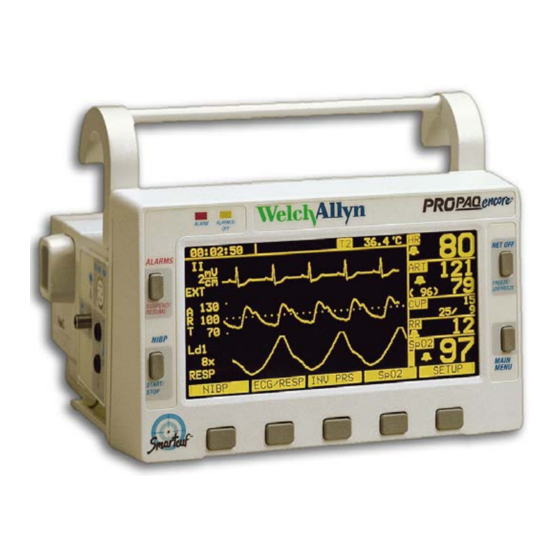
- Page 1 Propaq ® Encore Vital Signs Monitor Service Manual...
- Page 2 Welch Allyn. Welch Allyn assumes no responsibility for any injury to anyone, or for any illegal or improper use of the product, that may result from failure to use this product in accordance with the instructions, cautions, warnings, or statement of intended use published in this manual.
-
Page 3: Table Of Contents
Recommended Service Intervals ........6 Identifying Propaq Encore Configurations ......7 Self Test and Service Menus . - Page 4 Propaq Encore Software ........
-
Page 5: Safety Summary
WARNING Do not connect more than one patient to a monitor. Do not connect more than one monitor to a patient. WARNING Do not use the Propaq Encore in an MRI suite or a hyperbaric chamber. WARNING Do not autoclave the Propaq Encore. Autoclave accessories only if the manufacturer's instructions clearly approve it. - Page 6 WARNING To ensure patient safety, use only accessories recommended or supplied by Welch Allyn. For a list of those accessories, see the Welch Allyn Products and Accessories book that accompanied this manual (PN 810-0409-XX). Accessories must be used according to your hospital’s standards and the manufacturer’s recommendations.
-
Page 7: Definitions
Service Manual Safety Summary Definitions Note Identifies information that may be important to the reader. Caution Identifies conditions or practices that could result in damage to equipment or other property. WARNING Identifies conditions or practices that could result in personal injury. Symbols The following symbols appear in the monitor documentation and on monitor labels. - Page 8 Safety Summary Welch Allyn Propaq Encore Vital Signs Monitor The CE mark and notified body registration Single-use only (not reusable). number signify Propaq CS Series monitors 0123 have met all essential requirements of European medical device directives 93/42/ EEC. The Canadian Standards Association has...
-
Page 9: Overview
Overview Purpose and Scope The Propaq Encore Service Manual is intended as a reference for monitor maintenance and repair to the field replaceable unit (FRU) level (“Field Replaceable Units (FRUs)” page 117). This manual provides the technically qualified service person with troubleshooting information, repair procedures, and calibration and performance verification instructions. -
Page 10: Warranty Service
Note Save the shipping carton and packing material for repacking the Encore monitor in case it needs to be sent to a repair center or back to Welch Allyn for service. Warranty Service DO NOT ATTEMPT TO REPAIR the Encore monitor yourself during the warranty period. -
Page 11: Identifying Propaq Encore Configurations
“Functional Verification” page 11. Identifying Propaq Encore Configurations The following table identifies Propaq monitor configurations and how they are indicated. The model-option number and serial number are located on the back of the housing. The monitor indicators are located under the handle on the back. - Page 12 Overview Welch Allyn Propaq Encore Vital Signs Monitor Table 2. Expansion Module Option Configurations Option Printer Mainstream CO Sidestream CO Top Level Assembly Number Number 007-0046-XX Nellcor MP-203 007-0050-XX Nellcor MP-203 007-0047-XX Nellcor MP-203 007-0051-XX Masimo MS3 007-0069-XX Nellcor MP-405...
-
Page 13: Self Test And Service Menus
Refer to “Troubleshooting” on page 43 and contact Welch Allyn Technical Support for help. The Encore monitor contains software routines that make the Functional Verification and Calibration procedures quicker and easier. You access these routines through the Service Menus as indicated in each of the procedures. - Page 14 Overview Welch Allyn Propaq Encore Vital Signs Monitor...
-
Page 15: Functional Verification
Functional Verification Introduction The functional verification procedures ensure proper operation of the Encore monitor and its options. These procedures should be performed following module-level repairs, calibration, or whenever there is a question about the accuracy or safety of the patient functions. -
Page 16: Safety Tests
Welch Allyn cuff calibration kit, Welch Allyn PN 008-0012-XX Power supply adapter cable, Welch Allyn PN 008-0290-00 Physio Control LifePak 5 or LifePak 6s with appropriate Welch Allyn Defib Sync adapter to use as Defib Sync Marker pulse source Propaq ac power adapter (provided with the Encore) - Page 17 Dielectric Strength (Hi-Pot) Test Because of the close spacings of the monitor's internal components and the critical positioning of the insulation sheet within the monitor, Welch Allyn recommends that a dielectric strength test be performed following any procedure in which the monitor is opened.
-
Page 18: Functional Verification
Functional Verification Welch Allyn Propaq Encore Vital Signs Monitor Table 5. Summary of Connection Points and High-Voltage Test Potentials Tester's high-voltage terminal Tester's grounded return High-voltage test parameters connection connection All ECG leads on patient cable DC input connector; all pins connected... - Page 19 15.0V ± 0.1V. 8. Turn off the dc power supply. 9. Using the Welch Allyn dc power supply adapter cable, refer to the figure below for polarity and connect the dc power supply to the monitor's dc input connector on the right side panel.
- Page 20 Functional Verification Welch Allyn Propaq Encore Vital Signs Monitor 13. Vary the power supply from 12 V to 28 V and verify that the charging LED stays on. 14. Turn off the power supply. 15. Disconnect the supply from the monitor.
- Page 21 Service Manual Functional Verification Sequence for All Other Software Versions Press Result FREEZE/UNFREEZE Freezes the waveforms FREEZE/UNFREEZE Unfreezes the waveforms SETUP Changes the menu ALARMS Changes the display to ALARM STATUS SUSPEND (on menu) SUSPEND changes to RESUME ALARM SUSPEND/RESUME (button) Changes RESUME to SUSPEND ALL ALRM Changes display: Turn All Off, Are You Sure, Y or N...
- Page 22 Functional Verification Welch Allyn Propaq Encore Vital Signs Monitor 4. Set the patient simulator as follows: • ECG Waveform: normal sinus rhythm • ECG Rate: 80 beats per minute (bpm) • ECG Size: 1 mV amplitude • Resp Lead: Lead I •...
- Page 23 Service Manual Functional Verification 8. Check that an equipment alarm occurs. The EQUIPMENT ALERT / MULTIPLE message should accurately indicate the removed lead. The ALARM(S) OFF light will flash. • Software version 2.5X: The ECG FAULT will flash in the upper left-hand corner of the screen.
- Page 24 Functional Verification Welch Allyn Propaq Encore Vital Signs Monitor 27 . Check that the ALARM light is OFF . 28. Press MAIN MENU. Part 2— Electrical Check Use the same setup for this check described in “Setup” on page 17.
- Page 25 11. Disconnect the scope probe and ground clip and remove the wires from the connectors. 12. Using either a LifePak 5 or LifePak 6s and appropriate Welch Allyn adapter, set up the monitor and defibrillator according to instructions provided in the Defib Sync User’s Guide.
- Page 26 Functional Verification Welch Allyn Propaq Encore Vital Signs Monitor 10. After allowing a few seconds for settling, check that the mean pressure reading is 200 mmHg ±2 mmHg. 11. Remove the cable from the P1 input jack and verify that the message: P1 FAULT - TRANSDUCER NOT DETECTED appears.
- Page 27 Service Manual Functional Verification Pressure (mmHg) Tolerance (mmHg) ± ± ± ± 8. Reduce the pressure to 0 mmHg and check that the displayed readings (PR1 and PR2) are 0 ± 2 mmHg. 9. Close the bulb valve. 10. Press CANCEL. (If there is no CANCEL button at this time, go to the next step.) 11.
- Page 28 Functional Verification Welch Allyn Propaq Encore Vital Signs Monitor • Compatible adult SpO sensor for finger. • BIO-TEK Index 2 Series SpO Simulator with optical finger for sensor connection (or equivalent). Turn on power to the SpO simulator. 2. Connect the SpO cable to the monitor and the SpO sensor.
- Page 29 Press the printer's START/STOP button. The printer should begin continuous printing. 8. Press the START/STOP button to stop printing. 9. Lay the Propaq Encore on its back. 10. Press the START/STOP button to start printing. 11. Completely open the paper door on the bottom of the Expansion Module.
- Page 30 Functional Verification Welch Allyn Propaq Encore Vital Signs Monitor 15. Press the START/STOP button. 16. After the printer runs out of paper, check that an equipment alarm and PAPER OUT message appear on the monitor screen. 17 . Open the printer door and reload the paper into the printer.
- Page 31 Service Manual Functional Verification Local Barometric Pressure = 0.033421 x LUP x ATIS (ATIS in inches of Hg) 0.00131579 x LUP x ATIS (ATIS in mm of Hg) Example 1 a. The altitude is 5000 feet. The local uncorrected pressure (LUP) is determined from the following table to be 632.35.
- Page 32 Functional Verification Welch Allyn Propaq Encore Vital Signs Monitor Table 7. Local Uncorrected Barometric Pressure (LUP) as a Function of Altitude (Feet) Altitude Pressure Altitude Pressure Altitude Pressure Altitude Pressure (Feet) (mmHg) (Feet) (mmHg) (Feet) (mmHg) (Feet) (mmHg) -600 776.62 2400 696.36...
- Page 33 Service Manual Functional Verification Table 8. Local Uncorrected Barometric Pressure (LUP) as a Function of Altitude (Meters) Altitude Pressure Altitude Pressure Altitude Pressure Altitude Pressure (Meters) (mmHg) (Meters) (mmHg) (Meters) (mmHg) (Meters) (mmHg) 1000 674.11 2700 546.23 4400 438.74 6100 349.05 Mainstream CO Verification Procedure...
- Page 34 Functional Verification Welch Allyn Propaq Encore Vital Signs Monitor 12. Disconnect the CO sensor from the monitor. 13. Turn off the monitor. 14. Log the test date and results in your department log. WARNING Eliminate all the possibilities causing errors shown in the following table before performing the calibration procedure (“MSP Board (MCO2)
- Page 35 Service Manual Functional Verification 6. Verify that BARO TRUE and INT are within 15mmHg (5mmHg, typical) of the barometric pressure determined in step 4. Connect the test tubing setup shown in the figure below to both ends of a test water trap.
- Page 36 Functional Verification Welch Allyn Propaq Encore Vital Signs Monitor Caution Do not exceed 100mmHg during the following pressurization. Excessive pressure can open internal tubing connections and cause leakage. 15. Use the pump bulb to manually inflate the pressure to 100mmHg.
-
Page 37: Calibration
AND you have eliminated all possible faults as listed in the table . Equipment Needed You will need the following equipment to calibrate the Propaq Encore monitor. Part numbers are given for equipment available from Welch Allyn. Note All test equipment must be calibrated to function within parameters specified by the manufacturer, and be traceable to a national calibration standard. -
Page 38: Procedures
Tools necessary to disassemble and reassemble the Encore monitor. (See “Repair Procedures” on page 47 for a list of necessary tools and instructions on opening the monitor.) Procedures This section contains procedures for calibrating the Propaq Encore monitor: • Recharger board • Analog board •... -
Page 39: Recharger Supply Adjustments
F1 (on the right side panel) to open. If you suspect that RP3 has been misadjusted, turn it fully clockwise before connecting power to the dc input jack on the Propaq Encore. 6. Attach the dc power adapter cable to the variable dc power supply as shown figure... - Page 40 Calibration Welch Allyn Propaq Encore Vital Signs Monitor 0696-02 RIBBED (+) SMOOTH (-) Connect the adapter cable to the monitor’s dc input jack. 8. Verify that the input current from the variable dc power supply is less than 1.8A and that the green LED on the Encore’s right side panel is on.
-
Page 41: Display Voltage Adjustments
Service Manual Calibration Display Voltage Adjustments Note Do not adjust the display voltage unless the display has been changed and the lack of contrast between illuminated and non-illuminated pixels affects the display readability. The following calibration adjusts the monitor display’s high voltage supply which is located on the recharger board. -
Page 42: Main Power Supply Adjustments
Calibration Welch Allyn Propaq Encore Vital Signs Monitor 5. Reposition the tube to view the brightest area (now dim) and simultaneously a lighted area (pixels on). Adjust RP7 clockwise until the background area just begins to illuminate. Main Power Supply Adjustments The following procedures assume you are continuing from the recharger board calibration. -
Page 43: Calibrating Realtime Ecg Out
Service Manual Calibration Table 11. Main Power Supply Voltage Checks Supply Voltages Ref. Lead Pos. Lead Voltage Limits TP43 or TP1 TP13 +5.40 to +6.10 +5.6 TP43 or TP1 TP33 +5.55 to +5.70 IBP shield TP43 or TP1 P6, Pin 10 +2.47 to +2.53 C.L.P. -
Page 44: Non-Invasive Blood Pressure Calibration
Calibration Welch Allyn Propaq Encore Vital Signs Monitor Non-Invasive Blood Pressure Calibration Connect the cuff, digital pressure meter, bulb, and the Encore together with the cuff calibration kit. Using T-connectors from the kit, connect the cuff, pressure meter, and bulb. -
Page 45: Emi Null Adjustment
5. Adjust RP5 for a numeric reading of 200mmHg on the Encore monitor screen. Note If your Propaq Encore does not include a second pressure channel, skip Steps 6 - 10. 6. Move the IBP cable to the P2 connector. -
Page 46: Msp Board (Mco2) Calibration
Encore to ensure all monitoring functions and safety features operate normally. Because the battery was disconnected in the calibration procedures, you will Note need to reset the time, date and all saved settings. See the Propaq Encore Reference Guide for information on resetting these parameters. -
Page 47: Troubleshooting
PROGRAM FAULT: SETTINGS LOST, TIME/DAY RESET. If this message appears when the Propaq Encore is first turned on, it generally indicates a drained battery. The monitor can be used, but the time and date and all other settings will return to factory defaults each time the monitor is turned off. -
Page 48: Non-Recoverable Error Codes
Non-Recoverable Error Codes Non-recoverable errors are detected by software and indicate the Propaq Encore is no longer able to function properly and must be returned to Welch Allyn for service. Contact Welch Allyn Technical Support. When a non-recoverable error is found, the software attempts to put the error message and its number on the Propaq Encore display. -
Page 49: Battery Capacity Check
• displayed information. Refer to the Propaq Encore Reference Guide for battery care information and expected operating times. If the monitor fails to operate on battery for an extended period of time, follow the procedure below to check the capacity of the Encore’s lead acid battery. Lead acid batteries have a very limited shelf life;... - Page 50 Troubleshooting Welch Allyn Propaq Encore Vital Signs Monitor...
-
Page 51: Repair Procedures
See “Functional Verification” on page 11. Propaq Encore Software Propaq Encore system software is contained in PROMs (programmable read-only memory) on various system board. The following PROMs may require replacement during board exchange processes. See“Replacing PROMs” on page 70. -
Page 52: Required Tools
Propaq Encore Options Your Propaq Encore may contain an option module that attaches to the monitor. You must remove the option module before you can disassemble the monitor. For instructions on how to remove the expansion module, refer to “Replacing the Battery Pack”... -
Page 53: Field Replaceable Units In The Monitor
Service Manual Repair Procedures Monitor Only Monitor with SpO2 Monitor with Expansion Module 0696-10 Field Replaceable Units in the Monitor The front chassis of the monitor contains the following components: • insulator • Analog board with metal shield and insulator •... - Page 54 Repair Procedures Welch Allyn Propaq Encore Vital Signs Monitor Plastic Insulator Analog Board with Shield Digital Board Top Shield Digital Board Brackets EL Display Panel Front Chassis 0696-11 The rear chassis contains the following components: • Recharger board • Side panels (right and left) •...
-
Page 55: Replacing The Power Input Fuse
The F1 fuse protects the Recharger board circuitry against excessive current at the dc input connector. You do not need to disassemble the Propaq Encore to replace this fuse. Check fuse F1 if the ac power adapter is functioning properly and the following two conditions exist: •... -
Page 56: Replacing The Battery Pack
The battery fuse is not replaceable. If the battery is shorted, the entire pack must be replaced. Do not try to service the battery fuses. Insert a new battery pack into the Propaq Encore when the current battery no longer holds an adequate charge. Verify the battery charges to capacity according to “Battery... - Page 57 Service Manual Repair Procedures single battery cover removal Battery Battery Pack Cover Battery 0696-13 Pack Cable 2. Disconnect the battery pack cable from the battery pack. 3. Remove the battery pack from the monitor. 4. Store the battery in a safe place while disassembling the monitor. Removing the Dual Battery in Expansion Module The expansion module uses a dual battery pack.
- Page 58 Repair Procedures Welch Allyn Propaq Encore Vital Signs Monitor 2. Use the flat blade screwdriver to gently loosen the expansion module from the monitor (see inset above). 3. Slide the monitor forward until you can disconnect the battery pack cable from the monitor's power cable.
-
Page 59: Opening The Monitor
Service Manual Repair Procedures Remove the dual battery pack from the expansion module. 8. Store the battery in a safe place while disassembling the monitor and expansion module. Removing the Dual Battery in SpO Module The steps for removing the battery pack from the SpO module are identical to those in removing the battery from the expansion module, except you remove all screws on the rear panel. - Page 60 Repair Procedures Welch Allyn Propaq Encore Vital Signs Monitor 0696-18 Caution Before opening the casing more than one inch in the next step, disconnect the tube from the pressure transducer at the joint. Failure to disconnect the tubing may cause damage to the transducer or tubing.
- Page 61 Service Manual Repair Procedures 3. Spread the casing open to an angle of about 80 degrees. 4. Detach the following cables from the front chassis (indicated in figure below): • Cable to P5 on the Analog board, from the left side panel ECG connector on the rear chassis.
- Page 62 Repair Procedures Welch Allyn Propaq Encore Vital Signs Monitor Detach the two ribbon cables from the rear chassis: • Ribbon cable to P10 on the Recharger board, from the Digital board. • Ribbon cable to P11 on the Recharger board, from the Digital board.
-
Page 63: Closing The Monitor
2. Torque the six screws securing the front chassis to the rear chassis to 6.65in-lbs to 7 .35in-lbs (.75N-m to .83N-m). Replacing the Analog Board If a problem occurs with the Analog board, return the entire monitor to Welch Allyn for service. See “Technical Support Services”... - Page 64 Repair Procedures Welch Allyn Propaq Encore Vital Signs Monitor Note You do not need to lift the plastic insulator nor remove the metal shield to remove the Analog board. However, you must lift the insulator to calibrate the board. Remove the battery pack (“Replacing the Battery Pack”...
-
Page 65: Replacing The Digital Board
Torque the screws holding the Analog board to 3.8in-lbs to 4.2in-lbs (.43N-m to .47N-m). Replacing the Digital Board If a problem occurs with the Digital board, return the entire monitor to Welch Allyn for service. See “Technical Support Services” on page 6. - Page 66 Repair Procedures Welch Allyn Propaq Encore Vital Signs Monitor 5. Use the nut driver to loosen and remove the hex post. 6. Lift the Digital board up and out of the front chassis. Note The Digital board is connected to the EL display module by connector J1. This connector should detach easily.
- Page 67 Service Manual Repair Procedures When installing the Digital board: • Make sure the cable between the Digital board and the Recharger board is installed on the Digital board before placing the board in the front chassis. • Remove the shield on the top of the Digital board in order to reconnect the display cable.
-
Page 68: Replacing The El Display Module
Replacing the EL Display Module Caution Removing the EL display module may damage the electrically- conductive inner surface of the display filter. Welch Allyn recommends leaving the display unit in the front chassis unless you replace the display unit and the front chassis together. - Page 69 Service Manual Repair Procedures HOLD THE GASKET DOWN AT THESE POINTS ON BOTH REMOVE 4 SCREWS SIDES OF THE BOARD. AT CORNERS Caution In the next step, if the gasket lifts off the display filter at any point, you must inspect the display filter to verify that the conductive coating on the filter is still intact.
-
Page 70: Removing The Front Panel Buttons
Repair Procedures Welch Allyn Propaq Encore Vital Signs Monitor OTI Coating Approx. 0.125" 0696-33 When installing the display module: • Remove any dust from the display filter using pressurized de-ionized gas. • Orient the display module so that the J1 connector is toward the buttons. -
Page 71: Replacing The Recharger Board Fuse (F2)
Service Manual Repair Procedures 4. Remove the Digital board (“Replacing the Digital Board” on page 61). 5. Grasp the Silastic™ gray dome and pull the dome off the button post. 6. Squeeze the plastic button latches together and then push the button out the front of the panel. -
Page 72: Replacing Air Tubing
Repair Procedures Welch Allyn Propaq Encore Vital Signs Monitor Replacing Air Tubing Replace the NIBP tubing as a single assembly to ensure accurate tubing lengths. Refer to “Field Replaceable Units (FRUs)” on page 117 for the tubing assembly part number. -
Page 73: Replacing Cables
Service Manual Repair Procedures Replacing Cables If you suspect a cable to be faulty, check its continuity on all pins. If you need to replace a cable, refer to “Field Replaceable Units (FRUs)” on page 117 for part numbers.. When removing a cable, be sure to note the routing. It is important that the new cable is routed in the same manner. -
Page 74: Replacing Proms
Repair Procedures Welch Allyn Propaq Encore Vital Signs Monitor Replacing PROMs Read “Propaq Encore Software” on page 47. The PROMs require a special removal tool to replace them. (“Required Tools” page 48.) To prevent damage to the PROM sockets, do not use any other tools. -
Page 75: Cuff Fittings
Service Manual Repair Procedures Cuff Fittings Air system integrity in the NIBP system is essential for accurate measurements. Routine wear of the O-ring gasket located in the threaded fitting of the cuff hose can result in air leaks. If you encounter air leaks that cannot be found from the tests in this manual, replace the O-ring first. -
Page 76: Replacing The Recharger Board
Repair Procedures Welch Allyn Propaq Encore Vital Signs Monitor Replacing the Recharger Board The Recharger board is secured to the rear chassis by four screws. When removing the Recharger board, note the location of cables, plumbing, and screws and screw lengths. - Page 77 Service Manual Repair Procedures Screws Screws 0696 40 6. Lift out the Recharger board. Caution As you set the board in place during installation, keep the board clear of the power switch solder terminals to avoid binding against them. The terminals may become damaged if force is applied against them.
-
Page 78: Replacing The Pump
Repair Procedures Welch Allyn Propaq Encore Vital Signs Monitor Replacing the Pump New wires and a connector are provided with the replacement pump kit. Remove the battery pack (“Replacing the Battery Pack” on page 52). 2. Open the monitor (“Opening the Monitor”... -
Page 79: Replacing The Side Panels
Service Manual Repair Procedures Replacing the Side Panels The Propaq Encore side panels are complete assemblies. The side panels are sealed to the rear chassis with an adhesive gasket. A new gasket is provided with the new side panel kit. - Page 80 Repair Procedures Welch Allyn Propaq Encore Vital Signs Monitor INSERT SMALL SCREWDRIVER BETWEEN PLASTIC AND CLAMP TO RELIEVE TENSION AGAINST PLASTIC 5. Press the side panel out of the rear chassis. There is an adhesive gasket around the side panel which requires considerable force to separate. Do not pry against components.
- Page 81 Service Manual Repair Procedures Note Uncovering the protective paper in the next step exposes the adhesive on the gasket. Do not touch or otherwise contaminate the adhesive, or the adhesive may not properly seal the side panel. 4. On the new side panel, remove the protective paper from the gasket attached to the side panel.
-
Page 82: Expansion Module
Repair Procedures Welch Allyn Propaq Encore Vital Signs Monitor Expansion Module The expansion module housing contains one or all of the following: • printer mechanism with printer main board • MSP board (units with CO option) • connector side panel •... - Page 83 Service Manual Repair Procedures Opening the Expansion Module Rear Panel Separate the monitor and expansion module (“Removing the Dual Battery in Expansion Module” on page 53). For all sidestream CO options (226, 227 , 228, or 229) remove the front panel Note (“Replacing the Expansion Module Front Panel”...
- Page 84 Repair Procedures Welch Allyn Propaq Encore Vital Signs Monitor Closing the Expansion Module Make sure all cables are in place and the gaskets removed earlier are available. 2. Set the rubber gaskets in their proper places as shown in the figure below.
-
Page 85: Replacing The Expansion Module Front Panel
Service Manual Repair Procedures Replacing the Expansion Module Front Panel The front panel contains the printer buttons. Like the rear panel, the front is sealed to the chassis with a rubber O-ring gasket. This gasket can be re-used when replacing the front panel. -
Page 86: Replacing The Expansion Module Button Board And Buttons
Repair Procedures Welch Allyn Propaq Encore Vital Signs Monitor Replacing the Expansion Module Button Board and Buttons The expansion module contains a button board that has electrical contact areas to detect when an expansion module button is pressed. The front panel buttons are similar to the monitor buttons. -
Page 87: Replacing The Printer
Service Manual Repair Procedures Replacing the Printer This section provides instructions on removing and installing the printer mechanism and printer main board. These two components are provided as a replacement unit called the printer assembly. Caution Do not attempt to separate the printer mechanism from the printer main board. - Page 88 Repair Procedures Welch Allyn Propaq Encore Vital Signs Monitor Installing the Printer Lay the chassis on its back 2. Completely open the paper door. Caution As you install the printer assembly, rotate the printer door latch mechansim out of the way so it clears the chassis. The assembly fits snugly, but should not require much force to slide it in place.
-
Page 89: Opening The Spo2 Module
Service Manual Repair Procedures Opening the SpO Module Separate the SpO module from the monitor (“Removing the Dual Battery in SpO2 Module” on page 55). 2. Two tabs secure the SpO module rear panel to the SpO module chassis. Using a small screwdriver or your finger, press on each of the tabs inside the SpO module chassis while applying pressure to separate the rear panel from the chassis, as shown... -
Page 90: Replacing The Spo2 Circuit Boards
Repair Procedures Welch Allyn Propaq Encore Vital Signs Monitor Replacing the SpO Circuit Boards This describes how to replace the two SpO circuit boards in the SpO module and in the expansion module without a CO option. To replace SpO... -
Page 91: Replacing The Msp/Spo2 Circuit Boards
Service Manual Repair Procedures Replacing the MSP/SpO Circuit Boards This describes how to replace the MSP/SpO circuit boards in the expansion module with a CO option. To replace SpO boards in the SpO module and the expansion module without a CO option installed, see “Replacing the SpO2 Circuit Boards”... -
Page 92: Replacing The Sidestream Co2 Assemblies
Repair Procedures Welch Allyn Propaq Encore Vital Signs Monitor • set the two circuit boards and side panels in place, making sure that the boards are seated on the support tabs • torque screws to 4.75in-lbs to 5.25in-lbs (.54N-m to .59N-m) •... - Page 93 Service Manual Repair Procedures Removing the SSP/Stick board assembly: Caution When servicing the SSP and Stick board assemblies, be sure to note the tubing routing prior to disconnection. Always reassemble tubing exactly as removed. Stick Board Retainer Retainer Pump Pressure Transducer No connection 1097-18 SSP Board...
- Page 94 Repair Procedures Welch Allyn Propaq Encore Vital Signs Monitor Removing the Stick board from the SSP board: Disconnect the tubing from the pump and pressure transducer PT2 on the front- facing side of the SSP board and the pneumatic reservoir on the rear-facing side.
-
Page 95: Replacing Expansion Module Side Panels
Service Manual Repair Procedures Replacing Expansion Module Side Panels The side panels easily slide out after the chassis and rear panel are separated. If the patient connector side panel is being replaced, this side panel and the two circuit boards must be removed together before disconnecting the side panel from the circuit board. - Page 96 Repair Procedures Welch Allyn Propaq Encore Vital Signs Monitor...
-
Page 97: Technical Overview
Technical Overview This section describes the electronics of the Encore monitor and three of its options: Printer, Pulse Oximetry (SpO ), and Capnography (CO This section is intended as an aid to servicing at the field-replaceable unit level and contains only system-level and functional-level circuit descriptions. When replacing modules or components, refer to “Repair Procedures”... -
Page 98: System Description
The main functional modules (e.g. Analog Board, Recharger Board, Printer, SCP Board, etc.) reside in the housings. The figures on the following pages illustrate the location of the main functional modules in the Propaq Encore monitoring system housings. The Encore monitor electronics reside on three circuit boards within the monitor housing (front and rear chassis). - Page 99 Service Manual Technical Overview Filler Panel Rear Panel Main Housing Filler Panel Printer Expansion Module Option 221 printer Printer Door Front Panel, 1097-04 no SCO 2 SpO2 Connector Panel Rear Panel SpO 2 Board Speaker Panel Main Housing SCP Board Printer Expansion Module Option 223...
- Page 100 Technical Overview Welch Allyn Propaq Encore Vital Signs Monitor SpO 2 Connector Panel Rear Panel CO 2 Connector Panel SpO 2 Board Speaker Panel Main Housing MSP Board Expansion Module Option 224 SpO 2 MCO 2 Front Panel, no SCO 2...
- Page 101 Service Manual Technical Overview SpO 2 Connector Panel Rear Panel SpO 2 Board Speaker Panel Main Housing MSP Board Expansion Module Option 226 SpO 2 SSP Board Extender Board SCO 2 1097-08 Front Panel, Stick Board with SCO 2 SpO 2 Connector Panel Rear Panel SpO 2 Board Speaker Panel...
- Page 102 Technical Overview Welch Allyn Propaq Encore Vital Signs Monitor SpO 2 Connector Panel Rear Panel CO 2 Connector Panel SpO 2 Board Speaker Panel Main Housing 08 MSP Board Expansion Module SSP Board Option 228 SpO 2 Extender Board MCO 2...
- Page 103 Service Manual Technical Overview monitor system ENCORE SYSTEM MONITOR CHASSIS BLOCK DIAGRAM ANALOG BOARD (PATIENT DATA ACQUISITION, ANALOG-TO-DIGITAL CONVERSION, REAL-TIME ANALOG ISOLATED CPU, ECG OUT means optional PATIENT ISO/NON-ISO POWER SUPPLIES, configuration DATA REAL-TIME ECG OUT) LOCATED IN FRONT CHASSIS CUFF PRESSURE POWER/ DC POWER...
- Page 104 An accessory cable is available from Welch Allyn to allow connection of such a power source to the dc power input connector on the monitor’s right side panel.
- Page 105 Service Manual Technical Overview ISOLATED SUPPLIES...
- Page 106 Technical Overview Welch Allyn Propaq Encore Vital Signs Monitor Monitoring Electronics System The monitoring electronics reside on the Analog and Digital boards located in the front chassis assembly. These circuits • acquire the physiological signals from coupling devices (electrodes, transducers, and probes) •...
- Page 107 Service Manual Technical Overview NIBP Pneumatics The NIBP (cuff) system: • inflates the cuff to a target cuff pressure • converts the cuff air pressure to an electrical signal using a pressure transducer • deflates the cuff in a controlled manner while the monitoring electronics determines blood pressure •...
- Page 108 Technical Overview Welch Allyn Propaq Encore Vital Signs Monitor NIBP PNEUMATICS AT REST BETWEEN MEASUREMENTS TO DAP A-D CONVERTER PRIMARY TRANSDUCER SERVO (LINEAR) CUFF VALVE CLOSED BLEED DUMP VALVE PUMP VALVE OPEN OPEN SECONDARY TRANSDUCER TO DCP A-D CONVERTER ATMOSPHERIC PRESSURE...
- Page 109 Service Manual Technical Overview NIBP PNEUMATICS AT MAXIMUM TARGET PRESSURE TO DAP A-D CONVERTER PRIMARY TRANSDUCER CUFF SERVO (LINEAR) VALVE CLOSED BLEED DUMP VALVE PUMP VALVE OPEN CLOSED SECONDARY TRANSDUCER TO DCP A-D CONVERTER ATMOSPHERIC PRESSURE INCREASING PRESSURE (INFLATION) 0696-64 DECREASING PRESSURE (DEFLATION) PRESSURIZED (TARGET REACHED) NIBP PNEUMATICS DURING MEASUREMENT BLEED...
- Page 110 Technical Overview Welch Allyn Propaq Encore Vital Signs Monitor NIBP PNEUMATICS AFTER MEASUREMENT COMPLETE TO DAP A-D CONVERTER PRIMARY TRANSDUCER CUFF SERVO (LINEAR) VALVE CLOSED* BLEED DUMP VALVE PUMP VALVE OPEN OPEN SECONDARY TRANSDUCER TO DCP A-D CONVERTER ATMOSPHERIC PRESSURE...
-
Page 111: Cabling Diagrams
Service Manual Technical Overview Cabling Diagrams cabling diag... -
Page 112: Expansion Module And Printer
The Expansion Module is designed to house the Propaq Encore Printer and other circuit boards for additional parameters. The main circuit board in the Printer is the Printer Main Board. - Page 113 Service Manual Technical Overview PRINTER FUNCTIONAL BLOCK DIAGRAM P502 P150 FROM MOTOR PRINTER PWR (0..9) PRINTER BATTERY POWER P501 DRIVER PAPER OUT DET. P402 HEAD UP SYSTEM DET. PRINTER POWER P400 EXPANSION KEY BOARD P140 FROM/TO PROPAQ PRINT PRINTER HEAD (0..8) HEAD LOGIC EXPANSION...
-
Page 114: Pulse Oximetry (Spo2) Option
Technical Overview Welch Allyn Propaq Encore Vital Signs Monitor Pulse Oximetry (SpO ) Option The monitor pulse oximetry option (SpO ) hardware includes two circuit boards, a side- panel connector, and related hardware. The pulse oximetry option is installed in the pulse... - Page 115 Service Manual Technical Overview PULSE OXIMETRY BLOCK DIAGRAM AC COUPLED AMP INTERNAL INVERTING AMP PREAMP SWITCH (VAR. GAIN STAGE) PHOTODIODE SIGNAL FROM SENSOR COMPARE 1 COMPARE 2 PEAK DETECTOR PEAK DETECTOR IR SIGNAL SPLITTERS FILTERS DATA/CONTROLS TO/FROM SYNCHRONOUS RED SIGNAL DETECTOR SIGNAL TO SCP...
- Page 116 The data from the ADC is processed by the CPU and then sent to the SCP board for transmission to the Propaq Encore monitor's CPU. signal level is controlled through the variable gain stage of the inverting amplifier and the output current of the LED current driver.
-
Page 117: Capnography (Co2)
The Main Stream Processor circuit board (MSP board) is the major interface connection between several subsystems in the Expansion Module. This circuit board connects directly to the expansion connector, providing a direct interface to a Propaq Encore Display Processor system. - Page 118 Power Distribution System Power for CO and SpO circuit operations is derived solely from the expansion Connector. The principal supply comes from the Propaq Encore battery connections and an on-board switching power supply. Analysis Chamber (Bench) Analysis of the expired CO occurs in the bench.
- Page 119 Service Manual Technical Overview applications, a sample of exhaled gases is obtained through a small-diameter sampling tube and routed to the bench located on the Stick board. Unless otherwise noted, the following details are common for bench operation in both sampling methods.
- Page 120 Technical Overview Welch Allyn Propaq Encore Vital Signs Monitor...
-
Page 121: Field Replaceable Units (Frus)
Field Replaceable Units (FRUs) This identifies the available FRUs for the Propaq Encore. To order an FRU, contact Welch Allyn Technical Support as described in “Technical Support Services” on page 6. Description Part # Monitor Circuit Board Assemblies ANALOG PCB, 2XX (MODELS with S/N DA0, EA0) - Page 122 Field Replaceable Units (FRUs) Welch Allyn Propaq Encore Vital Signs Monitor Description Part # VALVE, BLEED/DUMP (VLV1, VLV2) 680-0050-00 VALVE, LINEAR SERVO (VLV3) 680-0049-01 Miscellaneous Components for Monitor FUSE, 2AG - 3A, SLO BLO, 250 V, EXTERNAL, 1 EACH 503-0058-00 FUSES, 3A PICO FUSE, 125 V, QTY.
- Page 123 CABLE, SCP-P4 TO PCP-P140 010-0054-00 CABLE, MSP-P4 TO PCP-P140/KEYPAD TO PCP-P400 010-0056-00 Labels, All Language Applications LABEL, LOGO, PROPAQ ENCORE 640-0421-00 LABEL, LOGO, WELCH ALLYN, PROPAQ ENCORE 640-0421-01 LABEL, MODEL 202 640-0350-00 LABEL, MODEL 204 640-0349-00 LABEL, MODEL 206 640-0348-00...
- Page 124 Field Replaceable Units (FRUs) Welch Allyn Propaq Encore Vital Signs Monitor Description Part # LABEL, LEFT SIDE PANEL, 2X2/RESP., AAMI, UNIVERSAL 640-0329-01 LABEL, LEFT SIDE PANEL, 2X2/RESP., HP, UNIVERSAL 640-0355-01 LABEL, LEFT SIDE PANEL, 2X4, AAMI, UNIVERSAL 640-0320-01 LABEL, LEFT SIDE PANEL, 2X4, HP, UNIVERSAL 640-0354-01 LABEL, LEFT SIDE PANEL, 2X4/RESP., AAMI, UNIVERSAL...
- Page 125 Service Manual Field Replaceable Units (FRUs) Description Part # LABEL, LEFT AND RIGHT KEYS WITH ALARM LEDS 640-0479-01 LABEL, LEFT AND RIGHT KEYS, NET OFF 640-0484-00 LABEL, LEFT AND RIGHT KEYS, NET OFF 640-0484-01 LABEL, PRINTER KEY PANEL 640-0372-00 Labels, German Applications LABEL, LEFT AND RIGHT KEYS WITH ALARM LEDS 640-0480-00 LABEL, LEFT AND RIGHT KEYS WITH ALARM LEDS...
- Page 126 Field Replaceable Units (FRUs) Welch Allyn Propaq Encore Vital Signs Monitor...
-
Page 127: A - Manufacturable Test Equipment
5 Ω 39 Ω 4.9 OHM AND 4.65 OHM LOADS .2 Ω 20 Ω .2 Ω 5 Ω CONNECTOR: 5-PIN, 0.156" CENTER MFR: METHODE; PN 3300-405-220 PROTOCOL PN: 610-0036-00 (REQUIRES INSERTION TOOL METHODE PN JT-11-156-ST) WELCH ALLYN PN 610-0036-00 0696-71... - Page 128 Manufacturable Test Equipment Welch Allyn Propaq Encore Vital Signs Monitor...
-
Page 129: B - Dynatech/Nevada Patient Simulator Modification
ECG and invasive pressure simulator channels are simultaneously connected to the monitor. Erroneous readings result. The patient simulator must be modified as described here before you can use both simulator channels with the Propaq Encore monitors with IBP . If only one simulator channel is used, the modification is unnecessary. - Page 130 Dynatech/Nevada Patient Simulator Modification Welch Allyn Propaq Encore Vital Signs Monitor...
Need help?
Do you have a question about the Propaq Encore and is the answer not in the manual?
Questions and answers