
Related Manuals for Vertiv XTE 601E Series


Summary of Contents for Vertiv XTE 601E Series
- Page 1 XTE 601E Series Equipment Enclosures Description and Installation Manual Specification Number: F2019015, F2019016...
- Page 2 The information contained in this document is subject to change without notice and may not be suitable for all applications. While every precaution has been taken to ensure the accuracy and completeness of this document, Vertiv assumes no responsibility and disclaims all liability for damages resulting from use of this information or for any errors or omissions.
-
Page 3: Table Of Contents
Vertiv™ XTE 601E Series Equipment Enclosures Description and Installation Manual TABLE OF CONTENTS Admonishments Used in this Document ......................... vi Important Safety Instructions ............................vii 1 Purpose of this Document ............................... 1 2 Product Description ................................1 2.1 General ........................................................1 2.2 Part Numbers .................................................... - Page 4 Vertiv™ XTE 601E Series Equipment Enclosures Description and Installation Manual 6.8 Preparing the Enclosure ..............................................34 6.9 Preparing the Concrete Pad ............................................35 6.10 Preparing to Lift the Enclosure ............................................ 36 6.11 Lifting the Enclosure ................................................37 6.12 Placing the Enclosure ................................................38 7 Sealing Primary Equipment Compartment Cable Entries ..................
- Page 5 Vertiv™ XTE 601E Series Equipment Enclosures Description and Installation Manual 15.1.2 Overview Diagrams ............................................68 15.1.3 ECU Power Connector ............................................. 71 15.2 Thermal Components and ECU Operation ......................................71 15.2.1 Primary Equipment Compartment ....................................... 71 15.2.2 Battery Boxes ................................................71 15.3 ECU User Interface ..................................................
-
Page 6: Admonishments Used In This Document
Vertiv™ XTE 601E Series Equipment Enclosures Description and Installation Manual Admonishments Used in this Document will likely DANGER! Warns of a hazard the reader be exposed to that will result in death or serious injury if not avoided. (ANSI, OSHA) -
Page 7: Important Safety Instructions
Vertiv™ XTE 601E Series Equipment Enclosures Description and Installation Manual Important Safety Instructions Safety Admonishments Definitions Definitions of the safety admonishments used in this document are listed under “Admonishments Used in this Document” on page vi. Safety and Regulatory Statements Refer to Section 4154 (provided with your customer documentation) for Safety and Regulatory Statements. - Page 8 Vertiv™ XTE 601E Series Equipment Enclosures Description and Installation Manual This page intentionally left blank. viii Proprietary and Confidential © 2022 Vertiv Group Corp.
-
Page 9: Purpose Of This Document
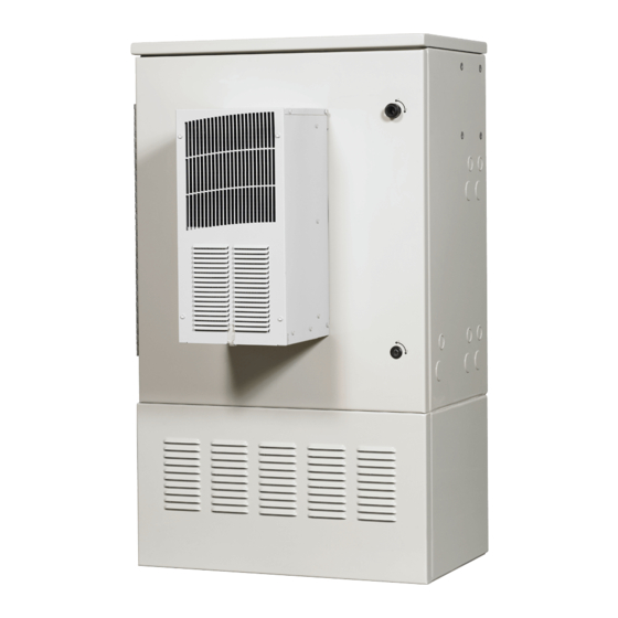
2 Product Description 2.1 General The XTE 601E Series 84” equipment enclosures are designed to house DC power, network electronics and battery backup equipment in a single enclosure. See Figure 2.1 for overall views of the enclosure. Figure 2.1 Overall Views of Enclosure... -
Page 10: Part Numbers
F2019016 support 1-battery string, NiCd Only 2.3 Application The XTE 601E Series 84” equipment enclosure is a full featured outdoor enclosure ideal for use in macro cell site and C-RAN applications. The XTE 601E Series 84" equipment enclosure... • provides a stable, secure, and water-tight environment for a -48 VDC power system, RAN equipment, outside plant equipment, and batteries supporting wireless telecommunications applications. -
Page 11: Safety Listed Ac Components
Vertiv™ XTE 601E Series Equipment Enclosures Description and Installation Manual 2.6 Safety Listed AC Components A typical XTE 601E Series 84" equipment enclosure includes the following listed or recognized components for United States: • GFI AC Receptacle: Legrand Pass & Seymour 1594-I / 1595-I - UL File E42190 Leviton 6599-I / 7599-I / 8599-I - UL File E48380 2.7 Commercial AC Service... -
Page 12: Typical Pad-Mount Overhead View
Vertiv™ XTE 601E Series Equipment Enclosures Description and Installation Manual NOTE! Typical battery weights… SAFT Tel.X+180, 180 Ah battery: 361 lbs (164kg) each -48V string. • Color: cool-white. • Finish: Finished in multistage dry powder polyester paint for maximum durability and performance against corrosion. - Page 13 Vertiv™ XTE 601E Series Equipment Enclosures Description and Installation Manual Figure 2.3 F2019016 Enclosure Dimensions 29.56 84.06 33.74 36.02 43.07 52.83 43.07 120° 65.32 Notes: 1. All dimensions are in inches, unless otherwise specified. 2. Minimum clearance of approximately 12 inches is required for airflow intake and exhaust.
- Page 14 Vertiv™ XTE 601E Series Equipment Enclosures Description and Installation Manual Figure 2.4 Equipment Mounting Rails Identification and Locations 12 RU 23” Equipment Note: (1) 4 RU 19” conversion bracket is included in the enclosure and can be used to adapt this 12 RU 23” section to 8 RU 23”.
- Page 15 Vertiv™ XTE 601E Series Equipment Enclosures Description and Installation Manual Figure 2.5 Enclosure Base Dimensions 28.82 4.00 4.50 4.00 4.00 4.00 4.16 4.16 3.86 3.60 4.84 3.60 F2019015 21.73 0.75 Dia. (4-places) 14.67 Front Enclosure Bottom View 28.82 4.00 4.50 4.00...
- Page 16 Vertiv™ XTE 601E Series Equipment Enclosures Description and Installation Manual Figure 2.6 Pad Mounting Rubber Barrier Pad (P/N 145396) Front Note: Enclosure Bottom View Dimensions are in inches. Proprietary and Confidential © 2022 Vertiv Group Corp.
- Page 17 Vertiv™ XTE 601E Series Equipment Enclosures Description and Installation Manual Figure 2.7 Optional Re-Usable Pad Mounting Drill Template (P/N F1010584 [145344]) Front Note: Enclosure Bottom View Dimensions are in inches. Proprietary and Confidential © 2022 Vertiv Group Corp.
- Page 18 Vertiv™ XTE 601E Series Equipment Enclosures Description and Installation Manual Figure 2.8 Optional Pour-in-Place Mounting Template (P/N F1010585 [554917]) Notes: 1. Dimensions are in inches. 2. “E” size hole position for mounting enclosure to pad. (Hilti Item # 00371808 Desc: HSL - 3 - B M 12/25)
-
Page 19: Enclosure Features And Options
Vertiv™ XTE 601E Series Equipment Enclosures Description and Installation Manual 2.9 Enclosure Features and Options Perspective Views: Refer to Figure 2.9, Figure 2.10, and Figure 2.11 for enclosure perspective views with major features identified Mounting Options: The enclosure is designed to be pad or platform mounted. It is to be lifted into place using the lifting eyebolts provided on the top of the enclosure. - Page 20 Vertiv™ XTE 601E Series Equipment Enclosures Description and Installation Manual • Door-activated convenience light. • Intrusion and light switches. • Alarm block. Grounding: The 10-position enclosure principal ground bar (alias Master Ground Bar [MGB]) is located at the rear of the primary equipment compartment.
- Page 21 Vertiv™ XTE 601E Series Equipment Enclosures Description and Installation Manual • Over and Under Temperature Conditions. • Primary Equipment Compartment Intrusion. • Fan Control Logic: The ECU controls provide independent control of the internal and external HX fans, adapting to the environment and equipment loads, and responding to faults, intrusions, etc.
- Page 22 Vertiv™ XTE 601E Series Equipment Enclosures Description and Installation Manual Figure 2.9 Front and Rear Perspective Views with Door Open and Major Features Identified 3500 W Equipment Heat Exchanger Compartment Front Rear String 2 String 1 F2019015 Battery Battery HVAC 4kW 48VDC W/500W Heater...
- Page 23 Vertiv™ XTE 601E Series Equipment Enclosures Description and Installation Manual Figure 2.10 F2019015 Perspective Views of Enclosure with Features LED Light Fixture (inside top of enclosure) Equipment GFCI Protected Compartment Convenience Outlet Alarm Blocks Intrusion Switch LED Light Switch Environmental...
- Page 24 Vertiv™ XTE 601E Series Equipment Enclosures Description and Installation Manual Figure 2.11 F2019016 Perspective Views of Enclosure with Features LED Light Fixture Equipment (inside top of enclosure) GFCI Protected Compartment Convenience Outlet Intrusion Switch LED Light Switch Front 250 A...
-
Page 25: Sequence Of Procedures
Vertiv™ XTE 601E Series Equipment Enclosures Description and Installation Manual 3 Sequence of Procedures 3.1 General The procedures listed in Table 3.1 are required to be performed in the order listed to fully install the enclosure. Other practices and manufacturer’s documents will be required to complete the installation of the system. This includes, but is not limited to: •... -
Page 26: Front Door, Locks, And Removable Panels
Vertiv™ XTE 601E Series Equipment Enclosures Description and Installation Manual 4 Front Door, Locks, and Removable Panels 4.1 Safety Precautions DANGER! RISK OF ELECTRICAL SHOCK, AC Proper actions, include, but not limited to: • Verify before contacting the enclosure that no current leakage or ground fault condition is present. - Page 27 Vertiv™ XTE 601E Series Equipment Enclosures Description and Installation Manual While holding the door closed, rotate and lower the swing-latch into the lock bed. See Figure 4.1. If required, replace padlock. Figure 4.1 Front Door Swing-Latch Figure 4.2 Front Door Wind Latch Wind Latch 90°...
-
Page 28: Intrusion Alarm
Vertiv™ XTE 601E Series Equipment Enclosures Description and Installation Manual 4.4 Intrusion Alarm The enclosure is equipped with a front door intrusion alarm switch. 4.4.1 F2019015 The intrusion alarm switch is connected to the ECU. The ECU sends an alarm signal to the alarm block whenever the front door is opened. - Page 29 Vertiv™ XTE 601E Series Equipment Enclosures Description and Installation Manual Figure 4.3 Intrusion Alarm and Light Switches Switch View Door Activated Intrusion Alarm Switch Door Activated Light Switch to ECU F2019015 Alarm Block F2019016 Note: This wiring of the intrusion switch results in a Normally Closed (open on alarm) circuit.
-
Page 30: Removing/Installing Rear Access Panels
Vertiv™ XTE 601E Series Equipment Enclosures Description and Installation Manual 4.6 Removing/Installing Rear Access Panels CAUTION! Spring loaded locking rods prevent opening the rear panels without performing “Opening the Front Door” on page 18, first. There are three rear access panels. - Page 31 Vertiv™ XTE 601E Series Equipment Enclosures Description and Installation Manual Figure 4.4 Removing/Installing Rear Access Panels These rods must be disengaged from the top rear access panel 1/4-turn lock (both sides) before removing the top rear access panel. Front View Un-hook safety chain from this bracket.
-
Page 32: Reversing The Hinge Side Of The Enclosure's Front Door
Vertiv™ XTE 601E Series Equipment Enclosures Description and Installation Manual 4.7 Reversing the Hinge Side of the Enclosure’s Front Door Refer to Method of Procedure (MOP13). 5 Installation Considerations NOTE! If holes are drilled into the exterior of this enclosure and not filled using a seal tight connector, the manufacturer’s warranty will be void. - Page 33 Vertiv™ XTE 601E Series Equipment Enclosures Description and Installation Manual • Torque wrench, 1/2" drive, recommended • Ratchet, 1/2" drive, 3/8" drive and 1/4" drive • Socket, 3/4" deep, 1/2" drive • Socket set, range from 1/4” to 1" •...
-
Page 34: Materials Required For Installation
Vertiv™ XTE 601E Series Equipment Enclosures Description and Installation Manual 5.4 Materials Required for Installation The following materials are required to install the enclosure. Table 5.1 Materials Required for Installation Description Part Number Quantity Comments 1/2" - 13 x 3.0 Lg... -
Page 35: Enclosure Placement
Vertiv™ XTE 601E Series Equipment Enclosures Description and Installation Manual 6 Enclosure Placement 6.1 Overview This section contains the procedures required for physical installation of the enclosure. 6.2 Site Selection The enclosure may be installed on a new or existing concrete pad, roof top, or metal platform. Obtain rights-of-way and other permits (building permit, electrical permit, etc.), depending on local codes and authorities, prior to installing the enclosure. -
Page 36: Site Ground
Vertiv™ XTE 601E Series Equipment Enclosures Description and Installation Manual 6.3 Site Ground DANGER! RISK OF ELECTRICAL SHOCK, GENERAL All enclosure grounding and ground ring must be installed and verified prior to connecting any power cables (AC or DC) and turning-up of enclosure. -
Page 37: Concrete Foundation Pad
Vertiv™ XTE 601E Series Equipment Enclosures Description and Installation Manual 6.4 Concrete Foundation Pad CAUTION! The compression strength of the concrete pad used must be a minimum of 4000 psi as determined by ASTM C39 test of compression strength of concrete cylinders. - Page 38 Vertiv™ XTE 601E Series Equipment Enclosures Description and Installation Manual Figure 6.2 Pad Sizing (from outside perimeter of enclosure to pad edge) = W + 48” (122 cm) (MINIMUM Pad Design) Proprietary and Confidential © 2022 Vertiv Group Corp.
-
Page 39: Form Preparation
Vertiv™ XTE 601E Series Equipment Enclosures Description and Installation Manual Figure 6.3 Ground Level View of Typical Pad Construction (w/out pour-in-place pad template) CABLE CONDUITS 2" (5.08 cm) ABOVE CONCRETE PAD WOODEN FORM 6" (15.24 cm) (2 x 6) TYPICAL CONCRETE PAD 2"... - Page 40 Vertiv™ XTE 601E Series Equipment Enclosures Description and Installation Manual • Backfill and tamp the trench(s) so the conduits remain in their position. • Remove the template(s) and fasten wooden stakes onto them to reposition them in the form area later.
-
Page 41: Transportation And Storage
Vertiv™ XTE 601E Series Equipment Enclosures Description and Installation Manual 6.6 Transportation and Storage DANGER! RISK OF ELECTRICAL SHOCK, GENERAL Do not install equipment showing any physical damage. If packaging is damaged, do not accept receipt from the shipper. CAUTION! PREVENT EQUIPMENT DAMAGE, PROPER HANDLING Do not stack nor lay the enclosure on its side. -
Page 42: Preparing The Enclosure
Vertiv™ XTE 601E Series Equipment Enclosures Description and Installation Manual Check the packing slip to make sure all components ordered were received. If there are missing components, notify your supervisor for further instructions. Carefully remove all packaging material from around the enclosure. Dispose of the packaging according to local practices. -
Page 43: Preparing The Concrete Pad
Vertiv™ XTE 601E Series Equipment Enclosures Description and Installation Manual 6.9 Preparing the Concrete Pad Procedure Clean all debris from the concrete pad or the platform where the enclosure will be placed. If still present, remove any jig alignment tool, bolts, etc. -
Page 44: Preparing To Lift The Enclosure
Vertiv™ XTE 601E Series Equipment Enclosures Description and Installation Manual 6.10 Preparing to Lift the Enclosure WARNING! PREVENT INJURIES, FROM LIFTING THE ENCLOSURE Follow all local safety practices while lifting the enclosure. Wear all locally approved safety gear. All persons working with lifting equipment must wear standard safety headgear, eye protection, and (when required) gloves. -
Page 45: Lifting The Enclosure
Vertiv™ XTE 601E Series Equipment Enclosures Description and Installation Manual 6.11 Lifting the Enclosure ALERT! Do not lift the enclosure with batteries, rectifiers, or converters installed. Procedure Ensure the front door is closed and latched. Inspect the lifting eyebolts and ensure eyebolts and roof are free of damage. -
Page 46: Placing The Enclosure
Vertiv™ XTE 601E Series Equipment Enclosures Description and Installation Manual Figure 6.5 Lifting the Enclosure eyebolts Typical sling arrangement Never use the sling without clevises or shackles as this may break the eyebolts Direction of pull Shackle The angle between the sling... - Page 47 Vertiv™ XTE 601E Series Equipment Enclosures Description and Installation Manual Figure 6.6 Attaching Enclosure to Optional Pour-in-Place Pad Template Note: Center mounting holes not used. Pad Mounting Rubber Barrier Pad (furnished with enclosure) Rear Optional Pour-in-Place Mounting Template Front Concrete Pad...
- Page 48 Vertiv™ XTE 601E Series Equipment Enclosures Description and Installation Manual Tap enclosure anchors loosely into position, leaving about 3/4" above the enclosure’s mounting surface. If a battery box is installed, align and loosely set the rear set of anchors first, then go to the front of the lowest battery box. Remove the L- shaped covers that hide the front anchor positions (refer to Figure 6.7) and tap enclosure anchors loosely into position.
- Page 49 Vertiv™ XTE 601E Series Equipment Enclosures Description and Installation Manual Figure 6.7 Enclosure Front Anchor Battery Box Covers Front “L” Shaped Front Anchor Position Access Covers “L” Shaped Front Anchor Position Access Covers Proprietary and Confidential © 2022 Vertiv Group Corp.
-
Page 50: Sealing Primary Equipment Compartment Cable Entries
Vertiv™ XTE 601E Series Equipment Enclosures Description and Installation Manual 7 Sealing Primary Equipment Compartment Cable Entries In keeping with local practices, seal all cable grommets and cable entry points. It is extremely important to maintain a well-sealed enclosure primary equipment compartment. Failure to do so can jeopardize the enclosure sensitive electronics, as well as the proper functioning of enclosure systems. - Page 51 Vertiv™ XTE 601E Series Equipment Enclosures Description and Installation Manual Figure 8.1 Enclosure Ground Ring Termination Block Locations Rear Ground Ring Termination Blocks (1/4-20 Studs on 5/8” centers) Proprietary and Confidential © 2022 Vertiv Group Corp.
-
Page 52: Ac Power
Vertiv™ XTE 601E Series Equipment Enclosures Description and Installation Manual 9 AC Power 9.1 Safety Precautions DANGER! RISK OF ELECTRICAL SHOCK, GENERAL All ground connections must be installed and verified, prior to connecting any power cables (AC or DC) and turning-up of enclosure. -
Page 53: Ac Input Connections
Vertiv™ XTE 601E Series Equipment Enclosures Description and Installation Manual 9.3 AC Input Connections Important Safety Instructions DANGER! Adhere to the “Important Safety Instructions” presented at the front of this document. The enclosure requires separate AC feeds for the GFCI outlet and optional AC battery heater kit (p/n 565616). The AC feed is connected directly to the GFCI outlet. - Page 54 Vertiv™ XTE 601E Series Equipment Enclosures Description and Installation Manual Figure 9.1 AC Input Knockout Locations 2.5 Conduit Rear Knockouts F2019015 2.5 Conduit Knockouts Junction Box Rear 2 Conduit Knockouts 2 Conduit Knockouts F2019016 Proprietary and Confidential © 2022 Vertiv Group Corp.
- Page 55 Vertiv™ XTE 601E Series Equipment Enclosures Description and Installation Manual Figure 9.2 AC Input Terminations Location JUNCTION BOX TO 120VAC, 15A SOURCE 15A GFI OUTLET Proprietary and Confidential © 2022 Vertiv Group Corp.
-
Page 56: Dc Power
Vertiv™ XTE 601E Series Equipment Enclosures Description and Installation Manual 10 DC Power 10.1 Safety Precautions DANGER! RISK OF ELECTRICAL SHOCK, GENERAL All ground connections must be installed and verified prior to connecting any power cables (AC or DC) and turning-up of enclosure. -
Page 57: Ecu Power Connectors (F2019015 Only)
Vertiv™ XTE 601E Series Equipment Enclosures Description and Installation Manual 10.5 ECU Power Connectors (F2019015 only) The ECU power connectors are located to the right of the ECU. NOTE! The ECU power connectors are connected at the factory. These connections should be only temporarily broken and made during a service event. -
Page 58: Osp Cables
Vertiv™ XTE 601E Series Equipment Enclosures Description and Installation Manual 11 OSP Cables 11.1 General DANGER! RISK OF ELECTRICAL SHOCK, OSP CABLES If joint buried cables are used, check the cable sheath for voltage in accordance with local standards. If voltage is detected, do not proceed with the installation. -
Page 59: Alarm Wiring
Vertiv™ XTE 601E Series Equipment Enclosures Description and Installation Manual 12 Alarm Wiring 12.1 Connecting External Alarms An alarm block is provided for the following purpose. • Enclosure Alarms Refer to Figure 12.1 and Figure 12.2 for location. F2019015 and F2019016: The alarm block is a 50 Pair split center block. Column A is internally connected to column B and Column C is internally connected to column D. - Page 60 Vertiv™ XTE 601E Series Equipment Enclosures Description and Installation Manual Figure 12.1 Local Alarm Block Schedule (F2019015) (cont’d on next page) R66 BLOCK# 1 CLIP ALARM SOURCE ECU/DOOR DOOR_INTRUSION SWITCH DC POWER FAILURE SYSTEM Alarm Block SURGE_SUPPRESSOR SURGE Location LIGHTNING_ARR ESTE R...
- Page 61 Vertiv™ XTE 601E Series Equipment Enclosures Description and Installation Manual Figure 12.1 Local Alarm Block Schedule (F2019015) (cont’d from previous page) R66 BLOCK# 2 CLIP ALARM SOURCE BUS_BAR_THEFT HIGH_HUMIDITY EXPLOSIVE_GAS HIGH_WATER SUMP_PUMP TOXIC_GAS WHT/ORG2 BATTERY_BREAKER ORG/WHT1 HEATER DC HEATER MINOR DC/DC CONVE RTER Proprietary and Confidential ©...
- Page 62 Vertiv™ XTE 601E Series Equipment Enclosures Description and Installation Manual Figure 12.2 Local Alarm Block Schedule (F2019016) (cont’d on next page) R66 BLOCK# 1 CLIP ALARM SOURCE DOOR_INTRUSION ECU/DOOR SWITCH DC POWER SYSTEM FAILURE Alarm Block Location SURGE SUPPRESSOR RECTIFIER_ FAILURE...
- Page 63 Vertiv™ XTE 601E Series Equipment Enclosures Description and Installation Manual Figure 12.2 Local Alarm Block Schedule (F2019016) (cont’d on next page) R66 BLOCK# 2 CLIP ALARM SOURCE BUS_BAR_THEFT HIGH_HUMIDITY EXPLOSIVE_GAS HIGH_ WATER SUMP_PUMP TOXIC_GAS WHT/ORG2 BATTE RY BATTERY_BREAKER BREAKERS ORG/WHT1...
- Page 64 Vertiv™ XTE 601E Series Equipment Enclosures Description and Installation Manual Figure 12.3 Typical Battery Alarm Wiring Proprietary and Confidential © 2022 Vertiv Group Corp.
-
Page 65: Batteries
Vertiv™ XTE 601E Series Equipment Enclosures Description and Installation Manual 13 Batteries 13.1 Safety Precautions DANGER! RISK OF ELECTRICAL SHOCK, GENERAL All ground connections must be installed and verified prior to connecting any power cables (AC or DC) and turning-up of enclosure. -
Page 66: Battery Boxes
Vertiv™ XTE 601E Series Equipment Enclosures Description and Installation Manual 13.2 Battery Boxes Up to two (2) battery boxes may be installed within the equipment frame. Each battery box houses one (1) -48V string of NiCd batteries. 13.2.1 Battery Boxes Heating The batteries may be heated through use of the optional battery heater kit (p/n 565616). -
Page 67: Battery Installation And Connection
Vertiv™ XTE 601E Series Equipment Enclosures Description and Installation Manual Table 13.1 Supported NiCd Batteries (F2019015, F2019016) Amp Hours Dimensions (inches) Battery per String @ 8 hrs H x W x D SAFT Tel.X+180 180 Ah 10.0 x 20.7 x 25.9 (overall) 13.4 Battery Installation and Connection... -
Page 68: Installing And Connecting Saft Nicd Batteries (F2019015, F2019016)
Vertiv™ XTE 601E Series Equipment Enclosures Description and Installation Manual 13.4.1 Installing and Connecting SAFT NiCd Batteries (F2019015, F2019016) Open the front door of the enclosure. Remove the front braces from each battery box and set braces and hardware aside for later use. - Page 69 Vertiv™ XTE 601E Series Equipment Enclosures Description and Installation Manual Figure 13.2 SAFT NiCd Battery String Layout and Block Mapping Diagram Front Place the battery (+) end (Block 1) with a bar code to the rightmost front position. See Figure 13.3.
- Page 70 Vertiv™ XTE 601E Series Equipment Enclosures Description and Installation Manual Remove all block-end covers (front and back) to access battery block terminals. Figure 13.4 Removing Block-end covers to Expose Terminals Exposed terminals after removing the block end-covers NOTE: The image shown is from other SAF T battery installations.
- Page 71 Vertiv™ XTE 601E Series Equipment Enclosures Description and Installation Manual Supporting the front end of the batteries, install the short interconnecting strap across the terminals on the rear of Blocks 1-2. Install the block end cover, and push both batteries to the rear of the shelf. Perform the same steps for Block 4-5.
- Page 72 Vertiv™ XTE 601E Series Equipment Enclosures Description and Installation Manual Figure 13.7 Measuring Voltage between (+) Terminal and Cable Interconnect Strap Front Block 4 Block 3 (+) Terminal (+) Terminal Connect Blocks 2-3 (short strap) and 3-4 (long strap) and secure with the bolts and wave washers. Re-install block end covers.
- Page 73 Vertiv™ XTE 601E Series Equipment Enclosures Description and Installation Manual Figure 13.8 Measuring Voltage between (+) Terminal 1 and (-) Terminal 5 Front Block 1 Block 5 (+) Terminal (-) Terminal Re-install the battery box front braces re-using hardware that was set aside.
-
Page 74: Initial Power Up
Vertiv™ XTE 601E Series Equipment Enclosures Description and Installation Manual 14 Initial Power Up 14.1 Safety Precautions DANGER! RISK OF ELECTRICAL SHOCK, GENERAL All ground connections must be installed and verified prior to turning-up of enclosure. DANGER! RISK OF ELECTRICAL SHOCK, AC Proper actions, include, but not limited to: Verify before contacting the enclosure that no current leakage or ground fault condition is present. -
Page 75: Climate Control Options (F2019015)
Vertiv™ XTE 601E Series Equipment Enclosures Description and Installation Manual • Use Non-Contact Voltage Detector to verify enclosure is not unsafe. • Close the circuit breaker in the power system supplying power to the ECU. • Allow ECU (if so equipped) a few minutes to complete start-up sequence. -
Page 76: Overview Diagrams
Vertiv™ XTE 601E Series Equipment Enclosures Description and Installation Manual 15.1.2 Overview Diagrams Figure 15.1 ECU and Thermal Components Overview Diagram (cont’d on next page) ECU (Environmental Control Unit) (see next sheet for connections) Heat Exchanger Equipment Compartment (Heat Exchanger) Battery Boxes Proprietary and Confidential ©... - Page 77 Vertiv™ XTE 601E Series Equipment Enclosures Description and Installation Manual Figure 15.1 ECU and Thermal Components Overview Diagram (cont’d from previous page, cont’d on next page) Main Compartment Thermister (TH1) Thermister J4 (Unused) (TH2) Unused Thermister (TH3) J7 (Alarm Relay...
- Page 78 Vertiv™ XTE 601E Series Equipment Enclosures Description and Installation Manual Figure 15.1 ECU and Thermal Components Overview Diagram (cont’d from previous page) ERROR CODES UP - Controller OK d01, d02 - Door Open, Ajar d03 - Maintenance Mode E01 - Therm 1 Fail (J1), Internal...
-
Page 79: Ecu Power Connector
Vertiv™ XTE 601E Series Equipment Enclosures Description and Installation Manual 15.1.3 ECU Power Connector The ECU power connectors are located to the right of the ECU. The ECU power connectors are pre-connected at the factory. These connections should only be temporarily broken and made during a service event. -
Page 80: Ecu Display Codes And Alarm Relays
Vertiv™ XTE 601E Series Equipment Enclosures Description and Installation Manual 15.3.2 ECU Display Codes and Alarm Relays Refer to Table 15.2. NOTE! Relay #1 activates where “1” has fault. Relay #2 activates where “2” has fault. Relay #3 activates where “3” has fault. - Page 81 Vertiv™ XTE 601E Series Equipment Enclosures Description and Installation Manual • External intrusion alarm (if silenced) re-activates. • All fans turn on. • Thermal control is restored. Table 15.1 ECU Display Codes and Alarm Relays Description External Alarm Relay ECU Display Code...
-
Page 82: Maintenance Mode
Vertiv™ XTE 601E Series Equipment Enclosures Description and Installation Manual 15.3.6 Maintenance Mode The system can be placed into the Maintenance Mode to perform such tasks as fan replacement. To enter the Maintenance Mode, open the front door and depress the Audible Alarm Cutoff / Maintenance / Reset pushbutton located on the ECU for more than 5 seconds but less than 10 seconds. - Page 83 Vertiv™ XTE 601E Series Equipment Enclosures Description and Installation Manual Figure 15.2 Cooling Zones (F2019015) 4 RU Near-Optimal Cooling 10 RU Ideal Cooling 7 RU Near-Optimal Cooling Proprietary and Confidential © 2022 Vertiv Group Corp.
-
Page 84: Climate Control Options (F2019016)
Vertiv™ XTE 601E Series Equipment Enclosures Description and Installation Manual 16 Climate Control Options (F2019016) NOTE! The F2019016 equipment cabinets are configured for use with Optional Battery Heater Kit. Optional Battery Heater Kit P/N (565616) (ordered separately) can be factory or field installed. -
Page 85: High Temperature Alarm
Vertiv™ XTE 601E Series Equipment Enclosures Description and Installation Manual 16.4 High Temperature Alarm The enclosure is equipped with a high-temperature alarm thermostat. The alarm setting is 65C. 16.5 Optimal Cooling Locations for Rack-Mount Equipment The ideal cooling location in the equipment rack is RU's 10-19 (from bottom of EQ rack). But near-optimal cooling can be achieved in any location RU's 1-19. -
Page 86: Maintenance, Troubleshooting, And Replacement Procedures
Vertiv™ XTE 601E Series Equipment Enclosures Description and Installation Manual 17 Maintenance, Troubleshooting, and Replacement Procedures 17.1 Important Safety Instructions DANGER! Adhere to the “Important Safety Instructions” starting on page vii. 17.2 Contact Information Refer to Section 4154 (provided with your customer documentation) for support contact information. -
Page 87: Battery Replacement
Vertiv™ XTE 601E Series Equipment Enclosures Description and Installation Manual Inspect the battery terminals. Make sure that the battery terminals are clean and the connections are tight. If necessary, clean and tighten the terminals in accordance with local practices, using approved cleaning solution. Reapply antioxidant compound (NO-OX-ID-A or equivalent). -
Page 88: Troubleshooting
Vertiv™ XTE 601E Series Equipment Enclosures Description and Installation Manual • use of an open flame, or any device that may create an open spark, and • use of de-icing fluid(s). 17.5 Troubleshooting 17.5.1 DC Power System Refer to the documentation furnished with the power system 17.5.2 Batteries... - Page 89 Vertiv™ XTE 601E Series Equipment Enclosures Description and Installation Manual When you open the front door and observe the ECU, you will see the d02 code displayed. This also indicates that there is a wiring issue with the intrusion switch somewhere.
-
Page 90: Replacement Procedures
Vertiv™ XTE 601E Series Equipment Enclosures Description and Installation Manual 17.6 Replacement Procedures 17.6.1 LED Light Replacement Procedure Unplug the LED unit that needs to be replaced. See Figure 17.1. Refer to Figure 17.2 and remove the nut securing the LED unit that needs to be replaced. -
Page 91: Heat Exchanger Internal And External Fan Replacement
Vertiv™ XTE 601E Series Equipment Enclosures Description and Installation Manual Figure 17.2 LED Light Replacement LED Light Bracket LED Unit Remove nut to replace LED unit. LED Light Fixture (inside top of enclosure) Front 17.6.2 Heat Exchanger Internal and External Fan Replacement DANGER! ELECTRICAL HAZARD/MECHANICAL HAZARD Risk of electric shock or being cut by moving fan blades. - Page 92 Vertiv™ XTE 601E Series Equipment Enclosures Description and Installation Manual Replacing an Internal or External Heat Exchanger Fan Perform the following steps to replace an internal or external heat exchanger fan. Remove the padlock from the enclosure door, if present.
- Page 93 Vertiv™ XTE 601E Series Equipment Enclosures Description and Installation Manual For an internal fan, perform the following steps. Save all hardware for re-use. Remove the top (3) and bottom (3) sets of bolts and lock washers from the fan outer mounting plate. Refer to Figure 17.4.
- Page 94 Vertiv™ XTE 601E Series Equipment Enclosures Description and Installation Manual Separate the defective fan from the fan inner mounting plate by removing the (4) sets of screws and star washers. Discard the defective fan. See Figure 17.5. Figure 17.5 Removing the Fan Inner Mounting Plate...
- Page 95 Vertiv™ XTE 601E Series Equipment Enclosures Description and Installation Manual Figure 17.6 Removing the Fan Shroud and Defective Fan (4 sets per fan) - 1/4-20 Rubberized Washers - 1/4 Flat Washers - 1/4-20 Hex Nut 1/4-20 Machine Screws Fan Shroud...
-
Page 96: Configured Equipment
17.7 Configured Equipment Equipment from Vertiv and 3rd-party manufacturers may be furbished and factory-installed in the XTE 601E 84" equipment enclosure. This may include equipment for DC power and distribution, AC power and backup (UPS), site management, RAN surge suppression, DC voltage up conversion, fiber connectivity, etc. -
Page 97: Accessories And Replacement Parts
Vertiv™ XTE 601E Series Equipment Enclosures Description and Installation Manual 18 Accessories and Replacement Parts Refer to Table 18.1 for list of accessories (AC) and replacement parts (RP). Table 18.1 Accessories and Replacement Parts Part Number Description 145396 Pad Mounting Rubber Barrier Pad (RP) - Page 98 Vertiv™ XTE 601E Series Equipment Enclosures Description and Installation Manual This page intentionally left blank. Proprietary and Confidential © 2022 Vertiv Group Corp.
- Page 99 Vertiv™ XTE 601E Series Equipment Enclosures Description and Installation Manual Connect with Vertiv on Social Media https://www.facebook.com/vertivI https://www.instagram.com/vertiv/ https://www.linkedin.com/company/vertiv/ https://www.twitter.com/vertiv/ Proprietary and Confidential © 2022 Vertiv Group Corp.
- Page 100 Vertiv.com | Vertiv Headquarters, 1050 Dearborn Drive, Columbus, OH, 43085, USA © 2022 Vertiv Group Corp. All rights reserved. Vertiv™ and the Vertiv logo are trademarks or registered trademarks of Vertiv Group Corp. All other names and logos referred to are trade names, trademarks or registered trademarks of their respective owners. While every precaution has been taken to ensure accuracy and completeness here, Vertiv Group Corp.
Need help?
Do you have a question about the XTE 601E Series and is the answer not in the manual?
Questions and answers