
Related Manuals for Vertiv XTE 802 Series


Summary of Contents for Vertiv XTE 802 Series
- Page 1 XTE 802G Generator Room Walk-In-Cabinet Description and Installation Manual Specification Number: F2019014...
- Page 2 The information contained in this document is subject to change without notice and may not be suitable for all applications. While every precaution has been taken to ensure the accuracy and completeness of this document, Vertiv assumes no responsibility and disclaims all liability for damages resulting from use of this information or for any errors or omissions.
-
Page 3: Table Of Contents
Vertiv™ XTE 802G Generator Room Walk-In-Cabinet Description and Installation Manual TABLE OF CONTENTS Admonishments Used in this Document .......................... v Important Safety Instructions ............................vi 1 Purpose of this Document ............................... 1 2 Product Description ................................1 2.1 General ........................................................1 2.2 Part Numbers .................................................... - Page 4 Vertiv™ XTE 802G Generator Room Walk-In-Cabinet Description and Installation Manual 9.2 Safety Precautions ................................................... 46 9.3 General ........................................................ 46 9.4 Master Ground Bar (MGB) ............................................... 46 9.5 Ground Bar (Interior) ................................................46 10 DC Power ................................... 52 10.1 Important Safety Instructions ............................................52 10.2 Safety Precautions ..................................................
-
Page 5: Admonishments Used In This Document
Vertiv™ XTE 802G Generator Room Walk-In-Cabinet Description and Installation Manual Admonishments Used in this Document will likely DANGER! Warns of a hazard the reader be exposed to that will result in death or serious injury if not avoided. (ANSI, OSHA) -
Page 6: Important Safety Instructions
Vertiv™ XTE 802G Generator Room Walk-In-Cabinet Description and Installation Manual Important Safety Instructions Safety Admonishments Definitions Definitions of the safety admonishments used in this document are listed under “Admonishments Used in this Document” on page v. You Must Follow Approved Safety Procedures DANGER! Performing the following procedures may expose you to hazards. - Page 7 Vertiv™ XTE 802G Generator Room Walk-In-Cabinet Description and Installation Manual General Safety Precautions The following precautions shall be observed at all time when handling and installing the enclosure: • Observe all safety precautions against personal injury and equipment damage. •...
- Page 8 Vertiv™ XTE 802G Generator Room Walk-In-Cabinet Description and Installation Manual Specific Safety Precautions DANGER! ELECTRICAL HAZARD The equipment shall be installed and serviced by trained service personnel in accordance with the applicable requirements of the current edition of the American National Standards Institute (ANSI) approved National Fire Protection Association's (NFPA) National Electrical Code (NEC) (NFPA 70) or Canadian Electrical Code;...
- Page 9 Vertiv™ XTE 802G Generator Room Walk-In-Cabinet Description and Installation Manual WARNING! PREVENT INJURIES, FROM LIFTING THE ENCLOSURE Follow all local safety practices while lifting the enclosure. Safety equipment, signage, traffic control and all required Personal Protective Equipment (PPE) shall be used.
- Page 10 Vertiv™ XTE 802G Generator Room Walk-In-Cabinet Description and Installation Manual This page intentionally left blank.
-
Page 11: Purpose Of This Document
Vertiv™ XTE 802G Generator Room Walk-In-Cabinet Description and Installation Manual 1 Purpose of this Document This document provides description and installation instructions for the XTE 802G Generator Room; Spec. No. F2019014, including associated foundation kits and platforms. Procedures related to the provisioning, start-up, and acceptance of the generator and associated equipment are not covered in this document. -
Page 12: Part Numbers
Vertiv™ XTE 802G Generator Room Walk-In-Cabinet Description and Installation Manual Figure 2-2: Illustration of XTE 802G Generator Room Mounted Next to an XTE 802 Walk-In-Cabinet (WIC) Front 2.2 Part Numbers Refer to Table 2-1 for applicable product part numbers. Table 2-1: XTE 802G Generator Room Part Numbers and Descriptions... -
Page 13: Application
Vertiv™ XTE 802G Generator Room Walk-In-Cabinet Description and Installation Manual 2.3 Application The XTE 802G Generator Room is designed to house and protect a Kohler 20 kW diesel generator. • The XTE 802G Generator Room is designed to provide secure and water-tight housing for the generator and associated equipment including the generator battery. -
Page 14: Dimensions, Weights, And Physical Specifications
Vertiv™ XTE 802G Generator Room Walk-In-Cabinet Description and Installation Manual 2.6 Dimensions, Weights, and Physical Specifications Dimensions • See Figure 2-3 for overall dimensions. • See Figure 2-4 for mounting hole dimensions without corner plates and Figure 2-5 for mounting hole dimensions with corner plates. - Page 15 Vertiv™ XTE 802G Generator Room Walk-In-Cabinet Description and Installation Manual Figure 2-3: Overall Dimensions Rear 80.00 Front Notes: 1. All dimensions are in inches, unless otherwise specified. 113.06 80.00 Right Side Left Side...
- Page 16 Vertiv™ XTE 802G Generator Room Walk-In-Cabinet Description and Installation Manual Figure 2-4: Mounting Hole Dimensions (without corner plates) 80.26 50.00 6.07 9.06 9.06 5.14 10.00 Bottom View 49.97 80.26 0.81 10.00 2.00 Front Notes: 1. All dimensions are in inches,...
- Page 17 Vertiv™ XTE 802G Generator Room Walk-In-Cabinet Description and Installation Manual Figure 2-5: Mounting Hole Dimensions (with corner plates) 82.99 7.07 68.85 7.07 Bottom View 68.85 82.99 1.13 2.43 Front Notes: 1. All dimensions are in inches, unless otherwise specified.
- Page 18 Vertiv™ XTE 802G Generator Room Walk-In-Cabinet Description and Installation Manual Figure 2-6: Working Space Clearances 80.00 Working Space Notes: 1. All dimensions are in inches, unless otherwise specified. Working Space 80.00 Top View Figure 2-7: Base Dimensions Notes: 1. All dimensions are in inches, Base unless otherwise specified.
- Page 19 Vertiv™ XTE 802G Generator Room Walk-In-Cabinet Description and Installation Manual Figure 2-8: Conduit Knockout Locations in Base Pan Bottom View Typ. Conduit Knockout (see Detail B) 20X Detail B Front Notes: 1. All dimensions are in inches, unless otherwise specified.
- Page 20 Vertiv™ XTE 802G Generator Room Walk-In-Cabinet Description and Installation Manual Figure 2-9: Base Side Plate Conduit Knockout Dimensions See Detail C See Detail A See Detail B 2X Detail A 2X Detail B Detail C Notes: 1. All dimensions are in mm [inches].
-
Page 21: Features And Options
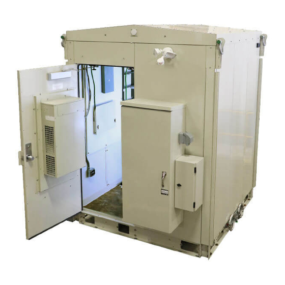
Vertiv™ XTE 802G Generator Room Walk-In-Cabinet Description and Installation Manual 2.7 Features and Options Perspective Views For illustrations of the XTE 802G, refer to the following. • Refer to Figure 2-10 for perspective views with major features identified. • Refer to Figure 2-11 for wall detail views. - Page 22 Vertiv™ XTE 802G Generator Room Walk-In-Cabinet Description and Installation Manual Access Door and Hardware • Type: 16 gauge galvanized steel commercial grade insulated door. • Size: 48" x 84" outward opening. • Frame: 16 gauge galvanized steel frame. • Door Lock: KABA Simplex L1000 Series, Model 1021B, Mechanical w/Best core.
- Page 23 Vertiv™ XTE 802G Generator Room Walk-In-Cabinet Description and Installation Manual Working Space Requirements See Figure 2-6 on page 8 for working space requirements. Foundation Options Helical Foundation Kit - Single Point Leveling (P/N D1000-0000-0101) (for Mounting XTE 802G Separate from the XTE 802) (Two Required) Consists of four (4) self drilling helicals, four (4) corner plates, leveling hardware, and stairs.
- Page 24 Vertiv™ XTE 802G Generator Room Walk-In-Cabinet Description and Installation Manual Figure 2-10: Perspective Views with Major Features Identified Lifting Hinges (4) Insulated Roof Wide Door E-Stop Switch Access Panels Intake Front Front WIC Interconnect Panels and Exterior Ground Bar Hardware...
- Page 25 Vertiv™ XTE 802G Generator Room Walk-In-Cabinet Description and Installation Manual Figure 2-11: Wall Detail Views (cont’d on next page)
- Page 26 Vertiv™ XTE 802G Generator Room Walk-In-Cabinet Description and Installation Manual Figure 2-11: Wall Detail Views (cont’d from previous page, cont’d on next page)
- Page 27 Vertiv™ XTE 802G Generator Room Walk-In-Cabinet Description and Installation Manual Figure 2-11: Wall Detail Views (cont’d from previous page, cont’d on next page)
- Page 28 Vertiv™ XTE 802G Generator Room Walk-In-Cabinet Description and Installation Manual Figure 2-11: Wall Detail Views (cont’d from previous page)
- Page 29 Vertiv™ XTE 802G Generator Room Walk-In-Cabinet Description and Installation Manual Figure 2-12: Top View of Floor and Floor Cable Entry Ports Roxtec Conduit Plate Generator Battery Front Door Front Door With Generator Installed Empty Figure 2-13: Door Intrusion Switch Location...
-
Page 30: Sequence Of Procedures
Vertiv™ XTE 802G Generator Room Walk-In-Cabinet Description and Installation Manual 3 Sequence of Procedures 3.1 General Perform the procedures in Table 3-1 (in the order listed) to fully install the XTE 802G. Other practices and manufacturer’s documents will be required to complete the installation of the system. This includes, but is not limited to: •... -
Page 31: Front Door
Vertiv™ XTE 802G Generator Room Walk-In-Cabinet Description and Installation Manual 4 Front Door 4.1 Safety Precautions DANGER! RISK OF ELECTRICAL SHOCK, AC Proper actions, include, but not limited to: • Verify before contacting the XTE 802G that no current leakage or ground fault condition is present. -
Page 32: Installation Considerations
Vertiv™ XTE 802G Generator Room Walk-In-Cabinet Description and Installation Manual 5 Installation Considerations NOTE! If holes are drilled into the exterior of this XTE 802G and not filled using a seal tight connector, the manufacturer’s warranty will be void. 5.1 Important Safety Instructions DANGER! Adhere to the “Important Safety Instructions”... -
Page 33: Tools And Test Equipment Required For Installation
Vertiv™ XTE 802G Generator Room Walk-In-Cabinet Description and Installation Manual 5.3 Tools and Test Equipment Required for Installation The following tools, test equipment and materials are required for the physical installation of the XTE 802G: • Non-contact voltage detector •... -
Page 34: Xte 802G Placement
Vertiv™ XTE 802G Generator Room Walk-In-Cabinet Description and Installation Manual 6 XTE 802G Placement 6.1 Overview This section contains the procedures required for physical installation of the XTE 802G. 6.2 Site Selection Obtain rights-of-way and other permits (building permit, electrical permit, etc.), depending on local codes and authorities, prior to installing the XTE 802G. -
Page 35: Foundation Kit Installation
Vertiv™ XTE 802G Generator Room Walk-In-Cabinet Description and Installation Manual 6.3 Foundation Kit Installation 6.3.1 Helical Foundation Kit Installation (P/N D1000-0000-0101) Helical Foundation Kit Installation Procedure Assemble the universal driving tool on the correct Kelly bar adapter. Connect Kelly bar adapter to Kelly bar on the drive head. - Page 36 Vertiv™ XTE 802G Generator Room Walk-In-Cabinet Description and Installation Manual Repeat steps 3 through 9 for all helicals paying attention to helical plate orientations and to accomplish 68.85 inch centers between all four helicals. See Figure 6-2. Figure 6-2: Helical Plate Orientations and Center to Center Adjustments Install leveling hardware in the center on each helical.
- Page 37 Vertiv™ XTE 802G Generator Room Walk-In-Cabinet Description and Installation Manual Install the four corner plates on the leveling hardware, one in each corner. See Figure 6-4. Figure 6-4: Install Four Corner Plates Level and secure all the leveling hardware on the corner plates and helicals, paying attention to 68.85 inch centers. The leveling hardware should not be installed outside the 3 inch radius of the helical pipe.
-
Page 38: Combo Platform Installation
NOTE! If more than one helical is unable to be driven to the required depth, please consult Vertiv engineering. For grounding purposes, NEC requires a minimum of 10 vertical feet of helical in the ground. Consult the NEC to determine if a ground ring is required for your installation. - Page 39 NOTE! If more than one helical is unable to be driven to the required depth, please consult Vertiv engineering. For grounding purposes, NEC requires a minimum of 10 vertical feet of helical in the ground. Consult the NEC to determine if a...
- Page 40 Vertiv™ XTE 802G Generator Room Walk-In-Cabinet Description and Installation Manual Figure 6-6: XTE 802 and XTE 802G Combo Helical Platform...
-
Page 41: Combo Concrete / Gravity Platform Installation (P/N D1000-0010-0179)
Vertiv™ XTE 802G Generator Room Walk-In-Cabinet Description and Installation Manual 6.4.2 Combo Concrete / Gravity Platform Installation (P/N D1000-0010-0179) Combo Concrete Platform This platform is designed to be set on concrete piers or pad and it accommodates both the XTE 802 and XTE 802G. The default location for the XTE 802G is to the right of the XTE 802 next to the ATS but the XTE 802G can be mounted on either side of the XTE 802 to support any site layout. - Page 42 Vertiv™ XTE 802G Generator Room Walk-In-Cabinet Description and Installation Manual Combo Concrete / Gravity Platform Installation Procedure The On The Ground (Gravity) Foundation Kit ships assembled so lift and set it on grade or concrete in desired location. Level the platform by adjusting the leveling hardware between the frame and the nine leveling points. Start by leveling the four corners first then adjust the remaining leveling points.
- Page 43 Vertiv™ XTE 802G Generator Room Walk-In-Cabinet Description and Installation Manual Figure 6-7: Combo Concrete Platform...
- Page 44 Vertiv™ XTE 802G Generator Room Walk-In-Cabinet Description and Installation Manual Figure 6-8: Combo Gravity Platform...
-
Page 45: Transportation And Storage
Vertiv™ XTE 802G Generator Room Walk-In-Cabinet Description and Installation Manual 6.5 Transportation and Storage Safety Precautions WARNING! PREVENT INJURIES, FROM LIFTING THE XTE 802G Follow all local safety practices while lifting the XTE 802G. Safety equipment, signage, traffic control and all required Personal Protective Equipment (PPE) shall be used. -
Page 46: Unpacking And Preparing The Xte 802G At The Installation Site
Vertiv™ XTE 802G Generator Room Walk-In-Cabinet Description and Installation Manual DANGER! RISK OF ELECTRICAL SHOCK, GENERAL Do not install equipment showing any physical damage. If packaging is damaged, do not accept receipt from the shipper. CAUTION! PREVENT EQUIPMENT DAMAGE, PROPER HANDLING Do not stack nor lay the XTE 802G on its side. -
Page 47: Preparing To Lift The Xte 802G
Vertiv™ XTE 802G Generator Room Walk-In-Cabinet Description and Installation Manual 6.7 Preparing to Lift the XTE 802G General Refer to “Transportation and Storage” on page 35. Required Equipment When Using a Crane: • A crane capable of lifting the shipped weight of the equipped XTE 802G plus a safety margin. - Page 48 Vertiv™ XTE 802G Generator Room Walk-In-Cabinet Description and Installation Manual Figure 6-9: Removing Base Cable Entry Covers Removable Base Cable Entry Covers...
-
Page 49: Lifting The Xte 802G
Vertiv™ XTE 802G Generator Room Walk-In-Cabinet Description and Installation Manual 6.8 Lifting the XTE 802G Safety Precautions DANGER! The maximum XTE 802G weight when lifted shall not exceed equipment ratings! Procedure (When Using a Crane) Close and latch all doors before lifting and placing the XTE 802G. - Page 50 Vertiv™ XTE 802G Generator Room Walk-In-Cabinet Description and Installation Manual Figure 6-10: Lifting the XTE 802G Lifting Brackets and Shackles (4 places) Typical sling arrangement Never use the sling without Direction clevises or shackles as this of pull may break the eyebolts...
-
Page 51: Placing The Xte 802G
Vertiv™ XTE 802G Generator Room Walk-In-Cabinet Description and Installation Manual 6.9 Placing the XTE 802G 6.9.1 On Approved Foundation Kit Approved Foundation Kits: • WIC Helical Foundation Kit • Combo Helical Platform • Combo Concrete / On The Ground Platform The following is a typical guide. - Page 52 Vertiv™ XTE 802G Generator Room Walk-In-Cabinet Description and Installation Manual Figure 6-11: Bolting XTE 802G to Pier WIC Mounting Plates and Hardware Sandwich WIC Mounting Plate Between Top Sets of Washers and Nuts Sandwich Pier Top Plate Between Bottom Sets of Washers and Nuts...
-
Page 53: Installing Interconnect Frame
Vertiv™ XTE 802G Generator Room Walk-In-Cabinet Description and Installation Manual 7 Installing Interconnect Frame A sheet metal frame is furnished to fill in the gap between the installed XTE 802 and XTE 802G. Refer to Figure 7-1 for assembly details. - Page 54 Vertiv™ XTE 802G Generator Room Walk-In-Cabinet Description and Installation Manual Figure 7-1: Interconnect Frame (cont’d from previous page)
-
Page 55: Sealing Cable Entries And Openings With Factory Cover-Plates
Vertiv™ XTE 802G Generator Room Walk-In-Cabinet Description and Installation Manual 8 Sealing Cable Entries and Openings with Factory Cover- Plates 8.1 General In keeping with best industry practices, seal all cable grommets penetrations against weather, rodent and insect intrusions. It is extremely important to maintain a well-sealed XTE 802G. Failure to do so can jeopardize the enclosed electronic equipment, as well as the proper functioning of the XTE 802G systems. -
Page 56: Grounding The Xte 802G
Vertiv™ XTE 802G Generator Room Walk-In-Cabinet Description and Installation Manual 9 Grounding the XTE 802G 9.1 Important Safety Instructions DANGER! Adhere to the “Important Safety Instructions” starting on page vi. 9.2 Safety Precautions DANGER! RISK OF ELECTRICAL SHOCK, GENERAL All XTE 802G grounding must be installed and verified prior to connecting any power cables (AC or DC) and turning-up of the XTE 802G. - Page 57 Vertiv™ XTE 802G Generator Room Walk-In-Cabinet Description and Installation Manual Figure 9-1: XTE 802G Master Ground Bar (MGB) Location Front Master Ground Bar (MGB) Location 24.00 1.48 11X .920 .910 4.00 2.44 2.00 1.56 .438 Master Ground Bar (MGB) .438 24X .438 x .688 OBROUND...
- Page 58 Vertiv™ XTE 802G Generator Room Walk-In-Cabinet Description and Installation Manual Figure 9-2: XTE 802G Ground Bar (Interior) Location Ground Bar Front...
- Page 59 Vertiv™ XTE 802G Generator Room Walk-In-Cabinet Description and Installation Manual Figure 9-3: XTE 802G Site Grounding Scheme (Helical Foundation) XTE 802G Site Grounding (Helical Foundation) Front Master Ground Bar (right side) (Contractor Installed) Terminate one provided #2 AWG solid pre-lugged...
- Page 60 Vertiv™ XTE 802G Generator Room Walk-In-Cabinet Description and Installation Manual Figure 9-4: Combo Site Grounding Scheme (Helical Foundation) XTE 802 and XTE 802G Combo Site Grounding (Helical Foundation) Front Master Ground Bar (right side) (Contractor Installed) Terminate one provided Helical...
- Page 61 Vertiv™ XTE 802G Generator Room Walk-In-Cabinet Description and Installation Manual Figure 9-5: Combo Site Grounding Scheme (Concrete / On the Ground Platform Foundation) XTE 802 and XTE 802G Combo Site Grounding (Concrete / On the Ground Platform Foundation) Front Master Ground Bar...
-
Page 62: Dc Power
Vertiv™ XTE 802G Generator Room Walk-In-Cabinet Description and Installation Manual 10 DC Power 10.1 Important Safety Instructions DANGER! Adhere to the “Important Safety Instructions” starting on page vi. 10.2 Safety Precautions DANGER! RISK OF ELECTRICAL SHOCK, GENERAL All ground connections must be installed and verified prior to connecting any power cables (AC or DC) and turning-up of the XTE 802G. - Page 63 Vertiv™ XTE 802G Generator Room Walk-In-Cabinet Description and Installation Manual Figure 10-1: Interior Lights Wiring Block...
-
Page 64: Optional +24 Vdc Smoke Detector Wiring Junction Box
Vertiv™ XTE 802G Generator Room Walk-In-Cabinet Description and Installation Manual 10.5 Optional +24 VDC Smoke Detector Wiring Junction Box Connect +24 VDC to the optional smoke detector wiring junction box as shown in Figure 10-2. Figure 10-2: Smoke Detector Wiring Junction Box... -
Page 65: Osp Cables
Vertiv™ XTE 802G Generator Room Walk-In-Cabinet Description and Installation Manual 11 OSP Cables 11.1 Important Safety Instructions DANGER! Adhere to the “Important Safety Instructions” starting on page vi. 11.2 Safety Precautions DANGER! RISK OF ELECTRICAL SHOCK, OSP CABLES If buried cables are used, check the cable sheath for voltage in accordance with local standards. If voltage is detected, do not proceed with the installation. -
Page 66: Alarm Wiring
Vertiv™ XTE 802G Generator Room Walk-In-Cabinet Description and Installation Manual 12 Alarm Wiring The XTE 802G is equipped with a door intrusion alarm switch. This switch can be wired to the alarm block located on the XTE 802. See Figure 12-1. Refer also to the XTE 802 documentation. - Page 67 Vertiv™ XTE 802G Generator Room Walk-In-Cabinet Description and Installation Manual This page intentionally left blank.
-
Page 68: Dc Power, Outdoor Enclosure & Service Contacts
Vertiv™ XTE 802G Generator Room Walk-In-Cabinet Description and Installation Manual 13 DC Power, Outdoor Enclosure & Service Contacts CUSTOMER SERVICE (PRE-SHIPMENT) Email CustomerService.ESNA@Vertiv.com Call Customer Service for purchase order status, expediting requests and order tracking. Phone 1.800.800.1280 option 1 CUSTOMER SUPPORT CENTER (POST-SHIPMENT) Email ESNACustomerSupportCenter@Vertiv.com... - Page 69 Vertiv™ XTE 802G Generator Room Walk-In-Cabinet Description and Installation Manual Connect with Vertiv on Social Media https://www.facebook.com/vertivI https://www.instagram.com/vertiv/ https://www.linkedin.com/company/vertiv/ https://www.twitter.com/vertiv/...
- Page 70 Vertiv.com | Vertiv Headquarters, 1050 Dearborn Drive, Columbus, OH, 43085, USA © 2020 Vertiv Group Corp. All rights reserved. Vertiv™ and the Vertiv logo are trademarks or registered trademarks of Vertiv Group Corp. All other names and logos referred to are trade names, trademarks or registered trademarks of their respective owners. While every precaution has been taken to ensure accuracy and completeness here, Vertiv Group Corp.
Need help?
Do you have a question about the XTE 802 Series and is the answer not in the manual?
Questions and answers