Table of Contents
Advertisement
Quick Links
- 1 Part Numbers
- 2 Wic Dimensions, Weights, and Physical Specifications
- 3 Wic Helical Foundation Kit Installation (P/N D1000-0000-0101)
- 4 Wic and Generator Combo Platform Installation
- 5 Elevated Wic and Generator Platform Installation (P/N D1000-0010- 0089-04, P/N D1000-0010-0089-06, P/N D1000-0010-0089-08, P/N D1000-0010-0089-10, P/N D1000-0010-0089-12)
- Download this manual
Advertisement
Table of Contents

Related Manuals for Vertiv XTE 801 Series


Summary of Contents for Vertiv XTE 801 Series
- Page 1 XTE 802 Series Walk-In-Cabinet (WIC) Description and Installation Manual (631-205-434), Revision D Specification Number: F2018009...
- Page 2 Vertiv Group Corporation is strictly prohibited. Vertiv and the Vertiv logo are trademarks or registered trademarks of Vertiv Co. All other names and logos referred to are trade names, trademarks or registered trademarks of their respective owners.
-
Page 3: Table Of Contents
WIC and Generator Placement ................50 Overview ..................................50 Site Selection ................................50 WIC Foundation Kit Installation ......................51 WIC Helical Foundation Kit Installation (P/N D1000-0000-0101) ......51 Vertiv | XTE 802 Series Walk-In-Cabinet (WIC) Description & Installation Manual (631-205-434) | Rev. D... - Page 4 AC Input Connections to Power Transfer Load Center (PTLC) E/W Automatic Transfer Switch (ATS) ..................... 92 DC Power ........................ 101 Important Safety Instructions ......................101 Safety Precautions ............................101 General ..................................101 Vertiv | XTE 802 Series Walk-In-Cabinet (WIC) Description & Installation Manual (631-205-434) | Rev. D...
- Page 5 Direct Air Cooling (DAC) and HVAC ..............111 Description ................................111 General Operation .............................. 111 Controller ...................................114 DC Power, Outdoor Enclosure & Service Contacts ........123 Vertiv | XTE 802 Series Walk-In-Cabinet (WIC) Description & Installation Manual (631-205-434) | Rev. D...
-
Page 6: Admonishments Used In This Document
SAFETY! Informs the reader of general safety information, reminders, precautions, or policies not related to a particular source of hazard or to fire safety. (ISO, ANSI, OSHA) Vertiv | XTE 802 Series Walk-In-Cabinet (WIC) Description & Installation Manual (631-205-434) | Rev. D... -
Page 7: Important Safety Instructions
• Ensure that all personnel on site are familiar with the first-aid kit location and emergency procedures in the event of an injury. • Never leave the WIC unattended. If leaving the site, close and secure the WIC. Vertiv | XTE 802 Series Walk-In-Cabinet (WIC) Description & Installation Manual (631-205-434) | Rev. D... -
Page 8: Voltages
Observe all battery safety precautions in this manual and in the battery instruction manual. These precautions should be followed implicitly at all times. Vertiv | XTE 802 Series Walk-In-Cabinet (WIC) Description & Installation Manual (631-205-434) | Rev. D... - Page 9 • If battery acid enters your eye, immediately flush your eye with running cold water for at least 15 minutes. Get medical attention immediately. • If battery acid contacts skin or clothing, wash immediately with soap and water. Vertiv | XTE 802 Series Walk-In-Cabinet (WIC) Description & Installation Manual (631-205-434) | Rev. D...
-
Page 10: Specific Safety Precautions
Work in a ventilated area and follow all safety procedures. At a minimum, wear safety glasses and gloves when working with batteries. Do not smoke. Vertiv | XTE 802 Series Walk-In-Cabinet (WIC) Description & Installation Manual (631-205-434) | Rev. D... - Page 11 Only properly trained operators shall operate the forklift. Do not exceed the lifting capacity of the forklift. Forklifts shall have a minimum fork length of 72 inches (183 cm). Vertiv | XTE 802 Series Walk-In-Cabinet (WIC) Description & Installation Manual (631-205-434) | Rev. D...
- Page 12 (a wrist strap for example) that is properly connected to a designated antistatic grounding point (on a framework, on an anti-static floor mat, etc.). ESD-protective packaging material shall also be used when carrying/shipping equipment containing static sensitive components. Vertiv | XTE 802 Series Walk-In-Cabinet (WIC) Description & Installation Manual (631-205-434) | Rev. D...
-
Page 13: Personal Protective Equipment (Ppe)
NOTE! When performing any step in procedures that requires removal of existing hardware, retain all hardware for use in subsequent steps, unless otherwise directed. Vertiv | XTE 802 Series Walk-In-Cabinet (WIC) Description & Installation Manual (631-205-434) | Rev. D... -
Page 14: Static Warning
If necessary to repair equipment containing static sensitive components, wear an appropriately grounded wrist strap, work on a conductive surface, use a grounded soldering iron, and use grounded test equipment. Vertiv | XTE 802 Series Walk-In-Cabinet (WIC) Description & Installation Manual (631-205-434) | Rev. D... -
Page 15: Purpose Of This Document
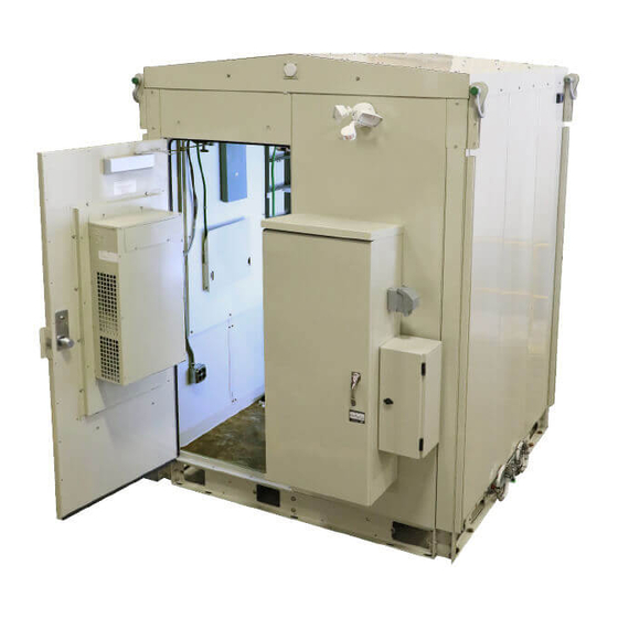
See Figure 1 for overall views of the XTE 802 Series Walk-In-Cabinet (WIC). Figure 1: Overall Views of XTE 802 Series Walk-In-Cabinet (WIC) Front Rear Vertiv | XTE 802 Series Walk-In-Cabinet (WIC) Description & Installation Manual (631-205-434) | Rev. D... -
Page 16: Part Numbers
VAC) controlled HVAC unit. (Vertiv P/N 151903.) ECUA18ACA036S-A5-299- 1.5 TON WALL MOUNTED HVAC, with controller, supply and VAR-0018 return grills and remote sensor (Vertiv P/N 151916). WIC Foundation Options D1000-0000-0101 WIC Helical Foundation Kit – (4) WIC Corner Plates, (1) Two NEQ.19785... - Page 17 Elevated WIC Generator Platform - This foundation kit is used Request in flood zones and areas where the site needs to be elevated. quote for elevations over 12' up to 20'. Vertiv | XTE 802 Series Walk-In-Cabinet (WIC) Description & Installation Manual (631-205-434) | Rev. D...
-
Page 18: Application
• Power Transfer Load Center (PTLC) – constructed in accordance with UL 67 Standard for Panelboards. Suitable for use as Service Entrance. • Automatic Power Transfer Switch: UL Listed to UL 1008, Standard for Transfer Switching Equipment. Vertiv | XTE 802 Series Walk-In-Cabinet (WIC) Description & Installation Manual (631-205-434) | Rev. D... -
Page 19: Safety Listed Ac Or Dc Components
States and/or Canada. The following examples of these may or may not be included in the WIC: • AC Terminal Blocks • Liquid Tight Flexible Metallic Conduit • GFI AC Receptacle • AC-DC Rectifiers • AC or DC Circuit Breakers Vertiv | XTE 802 Series Walk-In-Cabinet (WIC) Description & Installation Manual (631-205-434) | Rev. D... -
Page 20: Commercial Ac Service
Finish (all interior and exterior surfaces): Textured polyester powder coat, pebble gray (RAL 7032). • Alarms – Utility Loss Alarm Monitoring, SPD Fail, and generator Vertiv | XTE 802 Series Walk-In-Cabinet (WIC) Description & Installation Manual (631-205-434) | Rev. D... -
Page 21: Wic Dimensions, Weights, And Physical Specifications
• Fold down laptop desk. • Externally mounted color matched unistrut channels on each lifting strap for mounting external equipment. • Externally mounted GPS antenna mounting brackets. Vertiv | XTE 802 Series Walk-In-Cabinet (WIC) Description & Installation Manual (631-205-434) | Rev. D... - Page 22 86.50 Notes: 1. All dimensions are in inches, unless otherwise specified. Front 79.76 82.99 113.30 18.11 15.32 115.67 113.00 7.59 Left Side Right Side 79.74 Vertiv | XTE 802 Series Walk-In-Cabinet (WIC) Description & Installation Manual (631-205-434) | Rev. D...
- Page 23 80.26 50.00 6.07 9.06 9.06 5.14 10.00 Bottom View 80.26 49.97 0.81 10.00 2.00 Notes: 1. All dimensions are in inches, unless otherwise specified. Front Vertiv | XTE 802 Series Walk-In-Cabinet (WIC) Description & Installation Manual (631-205-434) | Rev. D...
- Page 24 Mounting Hole Dimensions (with corner plates) 82.99 7.07 68.85 7.07 Bottom View 68.85 82.99 1.13 2.43 Front Notes: 1. All dimensions are in inches, unless otherwise specified. Vertiv | XTE 802 Series Walk-In-Cabinet (WIC) Description & Installation Manual (631-205-434) | Rev. D...
- Page 25 Top View Space Figure 6: Base Dimensions Base 7.59 Front Left Side 79.74 79.76 Notes: 1. All dimensions are in inches, unless otherwise specified. 82.99 Vertiv | XTE 802 Series Walk-In-Cabinet (WIC) Description & Installation Manual (631-205-434) | Rev. D...
- Page 26 See Detail A 37.84 2x 9.92 2x 0.29 14.73 2x 12.34 2x 3.70 6.40 3x 3.70 6.40 1.85 1.85 Bottom Cover Panel Conduit Knockout Locations and Dimensions Vertiv | XTE 802 Series Walk-In-Cabinet (WIC) Description & Installation Manual (631-205-434) | Rev. D...
- Page 27 See Detail B 2X Detail A 2X Detail B Detail C Notes: 1. All dimensions are in mm [inches]. 2. All dimensions are to outside surface. Vertiv | XTE 802 Series Walk-In-Cabinet (WIC) Description & Installation Manual (631-205-434) | Rev. D...
-
Page 28: Wic Features And Options
• Base includes steel cover plates front and back to accommodate cabling. Interior Finish • Walls: White-textured Melamine panels over 5/8" gypsum board (1-hour fire-rated). Vertiv | XTE 802 Series Walk-In-Cabinet (WIC) Description & Installation Manual (631-205-434) | Rev. D... - Page 29 The base is also equipped with fork lift pockets that allow the use of a forklift to offload and lower to the mounting base at the site. Vertiv | XTE 802 Series Walk-In-Cabinet (WIC) Description & Installation Manual (631-205-434) | Rev. D...
- Page 30 Air conditioners are AC powered, and are refrigerant-based vapor compression devices. The heaters are electric strip type, integral to the a/c unit. Thermal Controller Marvair CoolLink. Vertiv | XTE 802 Series Walk-In-Cabinet (WIC) Description & Installation Manual (631-205-434) | Rev. D...
- Page 31 NOTE! Two (2) hole lugs are required on all ground bar terminations. Working Space Requirements See Figure 5 on page 25 for working space requirements. Vertiv | XTE 802 Series Walk-In-Cabinet (WIC) Description & Installation Manual (631-205-434) | Rev. D...
- Page 32 The stairs will then be attached to the WIC. This foundation kit is for use on top of grade. Vertiv | XTE 802 Series Walk-In-Cabinet (WIC) Description & Installation Manual (631-205-434) | Rev. D...
- Page 33 Each of the feet use single bolt leveling for adjustments. The generator will be anchored to the platform using the appropriate provided hardware. NOTE! For grounding purposes, ground generator platform to the WIC ground bar. Vertiv | XTE 802 Series Walk-In-Cabinet (WIC) Description & Installation Manual (631-205-434) | Rev. D...
- Page 34 10 feet in length. Each helical will be drilled into the ground to around 3 inches of grade or as low as desired. Confirm helical tops are level. Install the extensions on top of the helicals. Confirm extension tops are level. Vertiv | XTE 802 Series Walk-In-Cabinet (WIC) Description & Installation Manual (631-205-434) | Rev. D...
- Page 35 Elevated WIC and Generator Platform (Custom Item) Elevated Platforms above 12 feet up to 20 feet do not currently have ATT item numbers and therefore must be quoted. Vertiv | XTE 802 Series Walk-In-Cabinet (WIC) Description & Installation Manual (631-205-434) | Rev. D...
- Page 36 PTLC (Power Transfer Load Center) (Marvair DAC) E/W Automatic Transfer Switch (ATS) (Intersect) LED Outside Motion Light Motorized Exhaust Louver (DAC) Rear Back-Up HVAC (Marvair 1.5-Ton) Vertiv | XTE 802 Series Walk-In-Cabinet (WIC) Description & Installation Manual (631-205-434) | Rev. D...
- Page 37 NetSure 7100 Power System 24-Port Roxtec Assembly (24.24 EZ Entry) (5-places) Interior LED Lighting Smoke Detector (located in ceiling, (located in ceiling) 4-places) Vertiv | XTE 802 Series Walk-In-Cabinet (WIC) Description & Installation Manual (631-205-434) | Rev. D...
- Page 38 Figure 11: WIC Wall Detail Views (cont’d on next page) Vertiv | XTE 802 Series Walk-In-Cabinet (WIC) Description & Installation Manual (631-205-434) | Rev. D...
- Page 39 Figure 11: WIC Wall Detail Views (cont’d from previous page, cont’d on next page) Vertiv | XTE 802 Series Walk-In-Cabinet (WIC) Description & Installation Manual (631-205-434) | Rev. D...
- Page 40 Figure 11: WIC Wall Detail Views (cont’d from previous page, cont’d on next page) Vertiv | XTE 802 Series Walk-In-Cabinet (WIC) Description & Installation Manual (631-205-434) | Rev. D...
- Page 41 Figure 11: WIC Wall Detail Views (cont’d from previous page) Vertiv | XTE 802 Series Walk-In-Cabinet (WIC) Description & Installation Manual (631-205-434) | Rev. D...
- Page 42 Figure 12: Top View of WIC Floor Vertiv | XTE 802 Series Walk-In-Cabinet (WIC) Description & Installation Manual (631-205-434) | Rev. D...
- Page 43 Figure 13: WIC AC Conduit Routing Vertiv | XTE 802 Series Walk-In-Cabinet (WIC) Description & Installation Manual (631-205-434) | Rev. D...
- Page 44 Figure 14: WIC DC Panduit Routing Vertiv | XTE 802 Series Walk-In-Cabinet (WIC) Description & Installation Manual (631-205-434) | Rev. D...
- Page 45 Roxtec EzEntry 24/24 Equipment Bays Cable Entry Ports Cable Entry Ports Roxtec EzEntry 24/24 Roxtec EzEntry 24/24 Power System Front Components removed in illustration for clarity only. Vertiv | XTE 802 Series Walk-In-Cabinet (WIC) Description & Installation Manual (631-205-434) | Rev. D...
-
Page 46: Sequence Of Procedures
Describes the power up sequence for the AC power, the DC power, Initial Power Up and the batteries. Direct Air Cooling Describes the WIC thermal components. (DAC) and HVAC Vertiv | XTE 802 Series Walk-In-Cabinet (WIC) Description & Installation Manual (631-205-434) | Rev. D... -
Page 47: Front Door
Figure 17: Intrusion Alarm Switch Note: This wiring of the intrusion switch results in a Normally Closed (open on alarm) circuit. Front Door Intrusion Switch View Vertiv | XTE 802 Series Walk-In-Cabinet (WIC) Description & Installation Manual (631-205-434) | Rev. D... -
Page 48: Installation Considerations
• Route, splice, and verify the OSP cables. • Install and verify the alarm cables. • Install and verify the batteries. • Turn-up, verify, and adjust the system. Vertiv | XTE 802 Series Walk-In-Cabinet (WIC) Description & Installation Manual (631-205-434) | Rev. D... -
Page 49: Tools And Test Equipment Required For Installation
Outside the scope of this document, are the tools to fish, splice and terminate OSP Cables and laptop to setup the power system controller. Equipment associated with lifting the WIC by the eyebolts is listed separately, in a subsequent section. Vertiv | XTE 802 Series Walk-In-Cabinet (WIC) Description & Installation Manual (631-205-434) | Rev. D... -
Page 50: Wic And Generator Placement
• Use public road and street rights of way only where there is enough space to place the WIC and Generator and provide safe working conditions. The WIC and Generator should be easily accessible with Vertiv | XTE 802 Series Walk-In-Cabinet (WIC) Description & Installation Manual (631-205-434) | Rev. D... -
Page 51: Wic Foundation Kit Installation
Drive the helical until the helical plate is 11 inches above grade orientated as shown in Figure 18. Stop the driving tool assembly. Disconnect the universal driving tool from the helical plate. Vertiv | XTE 802 Series Walk-In-Cabinet (WIC) Description & Installation Manual (631-205-434) | Rev. D... - Page 52 Repeat steps 3 through 9 for all helicals paying attention to helical plate orientations and to accomplish 67.125 inch centers between all four helicals. See Figure 19. Figure 19: Helical Plate Orientations and Center to Center Adjustments Vertiv | XTE 802 Series Walk-In-Cabinet (WIC) Description & Installation Manual (631-205-434) | Rev. D...
- Page 53 The corner plates have elongated holes for 2 inches of play. There is a lot of room for adjustments to accomplish the 67.125 inch centers. See Figure 19 and Figure 22. Vertiv | XTE 802 Series Walk-In-Cabinet (WIC) Description & Installation Manual (631-205-434) | Rev. D...
- Page 54 Cut the helical at the appropriate height and install a fitted cap plate onto helical. Holes will need to be drilled to secure the cap plate to the helical. Vertiv | XTE 802 Series Walk-In-Cabinet (WIC) Description & Installation Manual (631-205-434) | Rev. D...
- Page 55 67.125 inch centers. See Figure 23. The top of the extensions are the same as the helicals, so see Figure 19 through Figure 22 for additional explanation. Vertiv | XTE 802 Series Walk-In-Cabinet (WIC) Description & Installation Manual (631-205-434) | Rev. D...
- Page 56 Once all hardware is installed connecting the WIC base to all corner plates, tighten and secure all the hardware. Install the WIC stairs using the provided hardware. Vertiv | XTE 802 Series Walk-In-Cabinet (WIC) Description & Installation Manual (631-205-434) | Rev. D...
-
Page 57: Wic On The Ground (Gravity) Foundation Kit Installation
Once all hardware is installed connecting the WIC base to the frame, tighten and secure the hardware. Install the WIC stairs using the provided hardware. Vertiv | XTE 802 Series Walk-In-Cabinet (WIC) Description & Installation Manual (631-205-434) | Rev. D... -
Page 58: Generator Foundation Kit Installation
Lift and set the generator, up to 20 KW, onto the platform and rodent guard then anchor in place. Connect all conduits and cabling to generator. Connect a ground cable from the generator platform to the WIC ground bar. Vertiv | XTE 802 Series Walk-In-Cabinet (WIC) Description & Installation Manual (631-205-434) | Rev. D... - Page 59 Cut the helical at the appropriate height and install a fitted cap plate onto helical. Holes will need to be drilled to secure the cap plate to the helical. Figure 25: Generator Helical Foundation Kit Up to 20 KW Vertiv | XTE 802 Series Walk-In-Cabinet (WIC) Description & Installation Manual (631-205-434) | Rev. D...
-
Page 60: All Generators Up To 30 Kw Helical Foundation Kit Installation (P/N D1000-0010-0109, Two Required)
Lift and set the generator, up to 30 KW, onto the platform and rodent guard then anchor in place. Connect all conduits and cabling to generator. Connect a ground cable from the generator platform to the WIC ground bar. Vertiv | XTE 802 Series Walk-In-Cabinet (WIC) Description & Installation Manual (631-205-434) | Rev. D... - Page 61 Cut the helical at the appropriate height and install a fitted cap plate onto helical. Holes will need to be drilled to secure the cap plate to the helical. Figure 26: Generator Helical Foundation Kit Up to 30 KW Vertiv | XTE 802 Series Walk-In-Cabinet (WIC) Description & Installation Manual (631-205-434) | Rev. D...
-
Page 62: All Generators Up To 30 Kw On The Ground (Gravity) Foundation Kit Installation (P/N D1001-0020-0062)
Connect all conduits and cabling to generator. Connect a ground cable from the generator platform to the WIC ground bar. Figure 27: Generators On the Ground (Gravity) Foundation Kit Vertiv | XTE 802 Series Walk-In-Cabinet (WIC) Description & Installation Manual (631-205-434) | Rev. D... -
Page 63: Wic And Generator Combo Platform Installation
Install the WIC stairs on the WIC using the provided hardware. Install the stairs for the generator area of the platform using the provided hardware. Vertiv | XTE 802 Series Walk-In-Cabinet (WIC) Description & Installation Manual (631-205-434) | Rev. D... - Page 64 Cut the helical at the appropriate height and install a fitted cap plate onto helical. Holes will need to be drilled to secure the cap plate to the helical. Vertiv | XTE 802 Series Walk-In-Cabinet (WIC) Description & Installation Manual (631-205-434) | Rev. D...
- Page 65 Figure 28: WIC and Generator Combo Helical Platform Vertiv | XTE 802 Series Walk-In-Cabinet (WIC) Description & Installation Manual (631-205-434) | Rev. D...
-
Page 66: Wic And Generator Combo Concrete/Gravity Platform Installation
Concrete area should be a minimum of 134" x 184" if above grade to accommodate for the stairs. WIC fully loaded is 6500 lbs. Platform is 2050 lbs. Heaviest Generator with full tank is 4436 lbs. Generator Wing Kit is 207 lbs. Vertiv | XTE 802 Series Walk-In-Cabinet (WIC) Description & Installation Manual (631-205-434) | Rev. D... - Page 67 Lift and set the generator, up to 30 KW, onto the platform and rodent guard then anchor in place. Connect all conduits and cabling. Figure 29: WIC and Generator Combo Concrete/Gravity Platform Vertiv | XTE 802 Series Walk-In-Cabinet (WIC) Description & Installation Manual (631-205-434) | Rev. D...
-
Page 68: Generator Wings Installation (P/N D1000-0020-0032)
Cut and layout rodent guard on the platform to fit generator foot print. Lift and set the generator, up to 30 KW, onto the platform and rodent guard then anchor in place. Connect all conduits and cabling. Vertiv | XTE 802 Series Walk-In-Cabinet (WIC) Description & Installation Manual (631-205-434) | Rev. D... - Page 69 Figure 30: Generator Wings Helical Foundation Kit Vertiv | XTE 802 Series Walk-In-Cabinet (WIC) Description & Installation Manual (631-205-434) | Rev. D...
- Page 70 Figure 31: Generator Wings Gravity or Concrete Mount Foundation Kit Vertiv | XTE 802 Series Walk-In-Cabinet (WIC) Description & Installation Manual (631-205-434) | Rev. D...
-
Page 71: Elevated Wic And Generator Platform Installation (P/N D1000-0010- 0089-04, P/N D1000-0010-0089-06, P/N D1000-0010-0089-08, P/N D1000-0010-0089-10, P/N D1000-0010-0089-12)
Drive the helical until the helical plate is 8 inches above grade, stop the driving tool assembly. Disconnect the universal driving tool from the helical plate. Vertiv | XTE 802 Series Walk-In-Cabinet (WIC) Description & Installation Manual (631-205-434) | Rev. D... - Page 72 WIC on the frame. See “WIC Lifting and Placement Procedures” starting on page 77. Lift and set generator on elevated platform in the designated location. Vertiv | XTE 802 Series Walk-In-Cabinet (WIC) Description & Installation Manual (631-205-434) | Rev. D...
-
Page 73: Transportation And Storage
Only properly trained operators shall operate the forklift. Do not exceed the lifting capacity of the forklift. Forklifts shall have a minimum fork length of 72 inches (183 cm). Vertiv | XTE 802 Series Walk-In-Cabinet (WIC) Description & Installation Manual (631-205-434) | Rev. D... -
Page 74: Unpacking And Preparing The Wic At The Installation Site
WARNING! Do not open any doors on the WIC unless it is secured in its mounted position, or securely restrained against unexpected movement or tipping. Vertiv | XTE 802 Series Walk-In-Cabinet (WIC) Description & Installation Manual (631-205-434) | Rev. D... -
Page 75: Preparing To Lift The Wic
If WIC base cable entry covers are installed, remove the bolts from the WIC base cable entry covers and set aside the covers and hardware for later re-use. See Figure 33. Vertiv | XTE 802 Series Walk-In-Cabinet (WIC) Description & Installation Manual (631-205-434) | Rev. D... - Page 76 Figure 33: Removing Base Cable Entry Covers Removable Base Cable Entry Covers Vertiv | XTE 802 Series Walk-In-Cabinet (WIC) Description & Installation Manual (631-205-434) | Rev. D...
-
Page 77: Lifting The Wic
Never work under the WIC while it is suspended above the ground. Lift the WIC off the truck and place it into its mounted position. Continue with the “Placing the WIC” procedure on 79. Vertiv | XTE 802 Series Walk-In-Cabinet (WIC) Description & Installation Manual (631-205-434) | Rev. D... - Page 78 Shackle The angle Shackle between the sling cables and the top of the cabinet shall not be less than 45° Top of WIC Vertiv | XTE 802 Series Walk-In-Cabinet (WIC) Description & Installation Manual (631-205-434) | Rev. D...
-
Page 79: Placing The Wic
VAC 150 W incandescent lamps inside the WIC to prevent condensation. Suspend lamps from cable racks to prevent contact with any structures or equipment inside the WIC. Vertiv | XTE 802 Series Walk-In-Cabinet (WIC) Description & Installation Manual (631-205-434) | Rev. D... - Page 80 Sandwich WIC Mounting Plate Between Top Sets of Washers and Nuts Sandwich Pier Top Plate Between Bottom Sets of Washers and Nuts Threaded Rod into Pier Vertiv | XTE 802 Series Walk-In-Cabinet (WIC) Description & Installation Manual (631-205-434) | Rev. D...
-
Page 81: Sealing Cable Entries
Replace port covers, Roxtec port frames and any other material removed during installation. Verify that cables are routed as required and that all cable entries are properly sealed. Vertiv | XTE 802 Series Walk-In-Cabinet (WIC) Description & Installation Manual (631-205-434) | Rev. D... -
Page 82: Grounding The Wic
If generator is being installed on a platform. The generator platform must have a 2 gauge ground wire run from it to a WIC exterior ground bar. Vertiv | XTE 802 Series Walk-In-Cabinet (WIC) Description & Installation Manual (631-205-434) | Rev. D... -
Page 83: Master Ground Bar (Mgb)
Ground Bar Location Location 24.00 1.48 11X .920 .910 4.00 2.44 2.00 1.56 Exterior Ground Bar .438 .438 24X .438 x .688 OBROUND 2X .56 Vertiv | XTE 802 Series Walk-In-Cabinet (WIC) Description & Installation Manual (631-205-434) | Rev. D... - Page 84 Termination locations space horizontally for 4/0 cable lugs of 1.200” maximum width allow for 0.125” minimum space between adjacent lugs. Busbar mounting detail omitted for clarity. Vertiv | XTE 802 Series Walk-In-Cabinet (WIC) Description & Installation Manual (631-205-434) | Rev. D...
- Page 85 Figure 37: Typical Master Ground Bar Terminations (cont’d from previous page) Vertiv | XTE 802 Series Walk-In-Cabinet (WIC) Description & Installation Manual (631-205-434) | Rev. D...
- Page 86 Figure 38: WIC Site Grounding Scheme (Helical Foundation) Vertiv | XTE 802 Series Walk-In-Cabinet (WIC) Description & Installation Manual (631-205-434) | Rev. D...
- Page 87 Figure 39: WIC Site Grounding Scheme (Concrete Mount Foundation Kit) Vertiv | XTE 802 Series Walk-In-Cabinet (WIC) Description & Installation Manual (631-205-434) | Rev. D...
- Page 88 Figure 40: WIC Site Grounding Scheme (Gravity Mount Foundation Kit and Elevated Platforms) Vertiv | XTE 802 Series Walk-In-Cabinet (WIC) Description & Installation Manual (631-205-434) | Rev. D...
- Page 89 Figure 41: WIC and Generator Combo Site Grounding Scheme (Helical Foundation) Vertiv | XTE 802 Series Walk-In-Cabinet (WIC) Description & Installation Manual (631-205-434) | Rev. D...
- Page 90 Figure 42: WIC and Generator Combo Site Grounding Scheme (Concrete Mount Foundation Kit) Vertiv | XTE 802 Series Walk-In-Cabinet (WIC) Description & Installation Manual (631-205-434) | Rev. D...
-
Page 91: Ac Power
Refer to “Grounding the WIC” on page 82 for information on WIC grounding. WIC AC Schematic The complete system schematics are included with each WIC. Vertiv | XTE 802 Series Walk-In-Cabinet (WIC) Description & Installation Manual (631-205-434) | Rev. D... -
Page 92: Ac Input Connections To Power Transfer Load Center (Ptlc) E/W Automatic Transfer Switch (Ats)
Torque the fasteners as required. Test the lead connections by gently pulling on them. After cables are installed, refer to the “Sealing Cable Entries” on page 81 and seal all cable entries and conduits. Vertiv | XTE 802 Series Walk-In-Cabinet (WIC) Description & Installation Manual (631-205-434) | Rev. D... - Page 93 Figure 43: Power Transfer Load Center (Reference Only) Vertiv | XTE 802 Series Walk-In-Cabinet (WIC) Description & Installation Manual (631-205-434) | Rev. D...
- Page 94 Figure 44: Typical Power Transfer Load Center (PTLC) Wiring Diagram Vertiv | XTE 802 Series Walk-In-Cabinet (WIC) Description & Installation Manual (631-205-434) | Rev. D...
- Page 95 This page is intentionally blank. Vertiv | XTE 802 Series Walk-In-Cabinet (WIC) Description & Installation Manual (631-205-434) | Rev. D...
- Page 96 Figure 45: AC Input and PTLC Internal Layout (Reference Only) Vertiv | XTE 802 Series Walk-In-Cabinet (WIC) Description & Installation Manual (631-205-434) | Rev. D...
- Page 97 This page is intentionally blank. Vertiv | XTE 802 Series Walk-In-Cabinet (WIC) Description & Installation Manual (631-205-434) | Rev. D...
- Page 98 This page is intentionally blank. Vertiv | XTE 802 Series Walk-In-Cabinet (WIC) Description & Installation Manual (631-205-434) | Rev. D...
- Page 99 This page is intentionally blank. Vertiv | XTE 802 Series Walk-In-Cabinet (WIC) Description & Installation Manual (631-205-434) | Rev. D...
- Page 100 This page is intentionally blank. Vertiv | XTE 802 Series Walk-In-Cabinet (WIC) Description & Installation Manual (631-205-434) | Rev. D...
-
Page 101: Dc Power
Refer to the schematic diagram provided with the WIC. Battery Installation and Wiring Refer to the DC power system instruction manual(s) for information regarding the installation and wiring of the batteries. Vertiv | XTE 802 Series Walk-In-Cabinet (WIC) Description & Installation Manual (631-205-434) | Rev. D... -
Page 102: External Dc Generator Wiring
Refer to the DC power system instruction manual(s) for information regarding the powering and operation of the power system. Refer to Figure 48 for a profile illustration of the power system. Vertiv | XTE 802 Series Walk-In-Cabinet (WIC) Description & Installation Manual (631-205-434) | Rev. D... - Page 103 Bottom adjacent wall, then transition to the DC Generator ceiling ladder rack, and then down into Cable Entrance the NetSure Power System. Vertiv | XTE 802 Series Walk-In-Cabinet (WIC) Description & Installation Manual (631-205-434) | Rev. D...
- Page 104 Apply electrical anti-oxidation compound to busbar mating surfaces. Components removed in illustration for clarity only. Generator Input Circuit Breaker Front NetSure Power System Distribution Cabinet Vertiv | XTE 802 Series Walk-In-Cabinet (WIC) Description & Installation Manual (631-205-434) | Rev. D...
- Page 105 (1RU = 1.75”) (accepts #12 hardware) 3.25 20.09 Top View 9.00 11.09 25.80 26.25 (15U) 7.00 (4U) Left Side View Front View Right Side View Vertiv | XTE 802 Series Walk-In-Cabinet (WIC) Description & Installation Manual (631-205-434) | Rev. D...
-
Page 106: Osp Cables
After cables are installed, refer to “Sealing Cable Entries” on page 81 and seal all cable entries. Installing Fiber Cables Install fiber cables using a 1.5" x 1.5" fiber routing duct provided along the length of cable rack for fiber management. Vertiv | XTE 802 Series Walk-In-Cabinet (WIC) Description & Installation Manual (631-205-434) | Rev. D... -
Page 107: Alarm Wiring
Equipment and connection for alarm collection and aggregation or multiplexing for remote reporting to a customer Network Operations Center (NOC) shall be specified and installed by the customer as required for the specific site capabilities and installation. Vertiv | XTE 802 Series Walk-In-Cabinet (WIC) Description & Installation Manual (631-205-434) | Rev. D... - Page 108 Figure 49: Alarm Block Wiring Vertiv | XTE 802 Series Walk-In-Cabinet (WIC) Description & Installation Manual (631-205-434) | Rev. D...
-
Page 109: Initial Power Up
Verify that the WIC has an approved connection to the local utility power supply. CAUTION! Prevent Equipment Damage: connect only 200 A, 240 VAC, 1-PH, 3 wire supply. Vertiv | XTE 802 Series Walk-In-Cabinet (WIC) Description & Installation Manual (631-205-434) | Rev. D... -
Page 110: Initial Power Up Sequence
CAUTION! Always allow components like rectifiers and the RA-ECU a few minutes to complete their start-up sequences. Refer to the power system instruction manual(s) supplied with the WIC or by the manufacturer for field- installed systems. Vertiv | XTE 802 Series Walk-In-Cabinet (WIC) Description & Installation Manual (631-205-434) | Rev. D... -
Page 111: Direct Air Cooling (Dac) And Hvac
WIC. Any time the air conditioner is providing mechanical cooling, the DAC is turned off and all louvers are closed. Vertiv | XTE 802 Series Walk-In-Cabinet (WIC) Description & Installation Manual (631-205-434) | Rev. D... - Page 112 Figure 50: F2018009 Direct Air Cooling (DAC) and HVAC Schematic Diagram (cont’d on next page) Vertiv | XTE 802 Series Walk-In-Cabinet (WIC) Description & Installation Manual (631-205-434) | Rev. D...
- Page 113 Figure 50: F2018009 Direct Air Cooling (DAC) and HVAC Schematic Diagram (cont’d from previous page) Vertiv | XTE 802 Series Walk-In-Cabinet (WIC) Description & Installation Manual (631-205-434) | Rev. D...
-
Page 114: Controller
From the main web page you can determine the status of the system, manually control the HVAC equipment, review the alarm information, review and upload event logs, and download software updates. Vertiv | XTE 802 Series Walk-In-Cabinet (WIC) Description & Installation Manual (631-205-434) | Rev. D... - Page 115 Figure 51: Controller Connection Sequence Vertiv | XTE 802 Series Walk-In-Cabinet (WIC) Description & Installation Manual (631-205-434) | Rev. D...
- Page 116 This page is intentionally blank. Vertiv | XTE 802 Series Walk-In-Cabinet (WIC) Description & Installation Manual (631-205-434) | Rev. D...
- Page 117 This page is intentionally blank. Vertiv | XTE 802 Series Walk-In-Cabinet (WIC) Description & Installation Manual (631-205-434) | Rev. D...
- Page 118 This page is intentionally blank. Vertiv | XTE 802 Series Walk-In-Cabinet (WIC) Description & Installation Manual (631-205-434) | Rev. D...
- Page 119 This page is intentionally blank. Vertiv | XTE 802 Series Walk-In-Cabinet (WIC) Description & Installation Manual (631-205-434) | Rev. D...
- Page 120 This page is intentionally blank. Vertiv | XTE 802 Series Walk-In-Cabinet (WIC) Description & Installation Manual (631-205-434) | Rev. D...
- Page 121 This page is intentionally blank. Vertiv | XTE 802 Series Walk-In-Cabinet (WIC) Description & Installation Manual (631-205-434) | Rev. D...
- Page 122 This page is intentionally blank. Vertiv | XTE 802 Series Walk-In-Cabinet (WIC) Description & Installation Manual (631-205-434) | Rev. D...
-
Page 123: Dc Power, Outdoor Enclosure & Service Contacts
Answers technical product and system questions; determines status of warranties and OSP.TAC@VertivCo.com contractual agreements for repair. Phone 1.800.800.5260 [1] Contact Account Management for custom configurations. [2] Contact Spare Parts for parts and accessories. Vertiv | XTE 802 Series Walk-In-Cabinet (WIC) Description & Installation Manual (631-205-434) | Rev. D... - Page 124 VertivCo.com | Vertiv Headquarters, 1050 Dearborn Drive, Columbus, OH, 43085, USA 631-205-434 (RD 02/19)
Need help?
Do you have a question about the XTE 801 Series and is the answer not in the manual?
Questions and answers