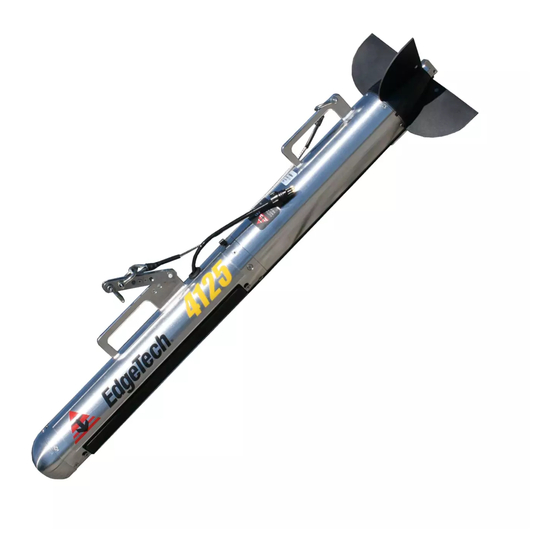
Edgetech 4125 User Manual
Side scan sonar system
Hide thumbs
Also See for 4125:
- User hardware manual (129 pages) ,
- Addendum (31 pages) ,
- Quick start manual (17 pages)

Related Manuals for Edgetech 4125


Summary of Contents for Edgetech 4125
- Page 1 4125 SIDE SCAN SONAR SYSTEM U S E R H A R D W A R E M A N U A L 0004823_REV_F October 2016 EdgeTech 4 Little Brook Road West Wareham, MA 02576 Tel: (508) 291-0057 Fax: (508) 291-2491...
- Page 2 The information, figures, and specifications in this manual are proprietary and are issued in strict confidence on condition that they not be copied, reprinted, or disclosed to a third party, either wholly or in part, without the prior, written consent of EdgeTech. Any reproduction of EdgeTech supplied software or file sharing is strictly prohibited.
-
Page 3: Attention - Read This First
ATTENTION – READ THIS FIRST! All personnel involved with the installation, operation, or maintenance of the equipment described in this manual should read and understand the warnings and cautions provided below. CAUTION! This equipment contains devices that are extremely sensitive to static electricity. -
Page 4: Hardware Variations And Compatibility
HARDWARE VARIATIONS AND COMPATIBILITY The 4125 Side Scan Sonar System contains both standard and proprietary hardware. At times, EdgeTech may change the standard components due to their availability or performance improvements. Although the component manufacturers—along with their models and styles—may change from unit to unit, replacement parts will generally be interchangeable. -
Page 5: About This Document
ABOUT THIS DOCUMENT We, the employees at EdgeTech, would like to thank you for purchasing 4125 Side Scan Sonar System. At EdgeTech, it is our policy to provide high-quality, cost-effective products and support services that meet or exceed your requirements. We also strive to deliver them on-time, and to continuously look for ways to improve them. -
Page 6: Revision History
Revision History REVISION DESCRIPTION DATE APPROVAL Update specifications 01/02/2011 Updated formatting/specs 01/21/2014 Updated specifications 05/03/2016 Updated for new tail cone 07/07/2016 and vertical scan ability Updated specifications and 10/28/2016 drawings 4125 SIDE SCAN SONAR SYSTEM 0004823_REV_F... -
Page 7: Warranty Statement
All equipment manufactured by EdgeTech is warranted against defective components and workmanship for a period of one year after shipment. Warranty repair will be done by EdgeTech free of charge. Shipping costs are to be borne by the customer. Malfunction due to improper use is not covered in the warranty, and EdgeTech disclaims any liability for consequential damage resulting from defects in the performance of the equipment. -
Page 8: Software Service Overview
Software Updates and Enhancements EdgeTech customers can download new software releases with all modifications and enhancements from the EdgeTech ftp site. Major software issues, should they occur, will be reported directly to the customer. New software releases consist of the following: ... -
Page 9: Returned Material Authorization
RETURNED MATERIAL AUTHORIZATION Prior to returning any equipment to EdgeTech, a Returned Material Authorization (RMA) number must be obtained. The RMA will help us identify your equipment when it arrives at our receiving dock and track the equipment while it is at our facility. The material should be shipped to the address provided in the section. - Page 10 5. If the equipment is the property of EdgeTech (formerly EG&G Marine Instruments Division), please insure for full value. 6. Fax one invoice, packing list, and a copy of the airway bill to EdgeTech upon shipment. 4125 SIDE SCAN SONAR SYSTEM...
-
Page 11: Customer Service
CUSTOMER SERVICE Customer service personnel at EdgeTech are always eager to hear from users of our products. Your feedback is welcome, and is a valuable source of information which we use to continually improve these products. Therefore, we encourage you to contact EdgeTech Customer Service to offer any suggestions... -
Page 12: Company Background
USBL positioning systems, and bathymetric systems—that have become standards in the industry. EdgeTech has also consistently anticipated and responded to future needs through an active research and development program. Current efforts are focused on the application of cutting-edge CHIRP and acoustic technology. -
Page 13: Table Of Contents
LIST OF TABLES ..........................xxi OVERVIEW ..........................1-1 4125 Series Applications ......................1-1 Main System Components ......................1-1 4125-P Portable Topside Processor ................... 1-1 4125 Rack Mount Topside ......................1-3 Towfish ............................1-3 Tow Cable ..........................1-4 Optional Equipment ........................1-5 1.7.1... - Page 14 3.11 System Activation and Test ..................... 3-17 3.11.1 Preparing a Wired ETHERNET LAN Connection ..............3-17 3.11.2 Preparing a Wireless ETHERNET LAN Connection (4125-P Only) ........3-18 3.11.3 Activating the 4125 Series System ..................3-18 3.12 Performing Pre-deployment Checks ..................3-19...
- Page 15 Config. 4: 4125, 23080 Cable - 300m Long ................C-7 C.1.3 Config. 6: 4125 + 15 lb. Keel Weight, 23080 Cable - 100m Long .......... C-8 C.1.4 Config. 8: 4125 + 15 lb. Keel Weight, 23080 Cable - 300m Long .......... C-9 C.1.5...
- Page 16 C.1.14 Config. 28: 4125 + Depressor Wing, A304874 Cable - 300m* Long ........C-19 C.1.15 Config. 30: 4125 + 15 lb. Keel Wt. + Dep. Wing, A304874 Cable - 100m ......C-20 C.1.16 Config. 32: 4125 + 15 lb. Keel Weight + Dep. Wing, A304874 Cable - 300m* ....C-21 C.1.17 Config.
- Page 17 xvii...
-
Page 18: List Of Figures
Figure 1-4: Optional Depressor Wing ......................1-6 Figure 1-5: Optional Inverted HullScan Bracket ..................1-6 Figure 2-1: 4125 Series Dual Frequency Side Scan Sonar System Overall Block Diagram (Wireless for Portable Topside Only) ..........................2-4 Figure 2-2: 4125-P Portable Case ICD Drawing ..................2-5 Figure 2-3: 4125-P Portable Topside Processor Wiring Diagram ............... - Page 19 Figure 3-12: Cable grip attached to Depressor Wing Mounting Point............ 3-14 Figure 3-13: Towfish with Tow Cable Connected and Attached .............. 3-15 Figure 3-14: DISCOVER 4125 Towfish Control Tab .................. 3-19 Figure 3-15: Performing a Rub Test ......................3-20 Figure 3-16: Rub Test Screen Shot ......................
- Page 20 4125 SIDE SCAN SONAR SYSTEM 0004823_REV_F...
-
Page 21: List Of Tables
Table 5-1: Topside Processor System Troubleshooting Guide ..............5-19 Table 5-2: 4125 Towfish Troubleshooting Guide ..................5-21 Table 5-3: Part Numbers for Major 4125-P Topside Processor Components .......... 5-24 Table 5-4: Part Numbers for Major 4125 Towfish Components ..............5-2... -
Page 23: Overview
1.2 Main System Components The 4125 Series Dual-frequency Side Scan Sonar System is composed a 4125-P Portable Topside Processor or 4125 Rack Mount Topside, a 4125 Towfish (commonly called a Towfish), and a tow cable. 1.3 4125-P Portable Topside Processor The 4125-P Portable Topside Processor is shown in 1-1. -
Page 24: Figure 1-1: 4125 Laptop And Portable Topside Processor
1.0 OVERVIEW The topside unit includes a laptop computer with Windows 7 and the EdgeTech DISCOVER 4125 Side Scan Sonar software preinstalled. DISCOVER 4125 provides control, storage, and display of the sonar data. The data can be stored in XTF and JSF formats. -
Page 25: 4125 Rack Mount Topside
1.4 4125 Rack Mount Topside The 4125 system can also be ordered with a 19” 2U rack mount option instead of the portable topside. This version of the processor is intended for permanent mounting in a sheltered section of the survey vessel. -
Page 26: Tow Cable
Tow cable is a RG58 coax cable which includes a single conductor and shield. Up to 600 meters of coax cable can be used. Contact EdgeTech Customer Service for available cable lengths other than the supplied 50-meter cable. A cable grip is also included for attaching the tow cable to a shackle on the towing arm of the towfish. -
Page 27: Optional Equipment
Figure 1-3: 4125 Tow Cable 1.7 Optional Equipment Optional equipment that can be installed and used with a 4125 Series Dual-frequency Side Scan Sonar System includes: Keel Weight Kit (Part Number 0008464) Depressor Wing Kit (Part Number 0007860) ... -
Page 28: Keel Weight
In this configuration the towfish can be used to scan the hulls of ships. Installation of the HullScan Kit option is in sub-section 3.9.1: I Kit. NSTALLING THE Figure 1-5: Optional Inverted HullScan Bracket 4125 SIDE SCAN SONAR SYSTEM 0004823_REV_F... -
Page 29: Specifications
NOTE: All specifications are subject to change without notice. 2.1 4125 Topside Processor Specs The specifications for the 4125-P Portable and 4125 Rack Mount Topside Processor are shown below: 4125 PORTABLE TOPSIDE 4125 RACK MOUNT TOPSIDE 19.0 cm (7.3 in.) high 8.3 cm (3.25 in.) high... -
Page 30: Technical Descriptions Of Internal Components
This section provides an overall general description of the hardware elements comprising the 4125-P Portable and 4125 Rack Mount Topside Processors of the 4125 Series Dual-frequency Side Scan Sonar System. This information, which includes printed circuit board summary descriptions, chassis photos, component call-outs, and a wiring diagram, can be useful for troubleshooting purposes and installing optional equipment. - Page 31 However, an overall block diagram of the system is shown 2-1. IGURE An ICD case drawing and a wiring diagram of the 4125-P Portable Topside Processor are shown in IGURE 2-3, respectively. The electronics chassis is shown in 2-4.
-
Page 32: Figure 2-1: 4125 Series Dual Frequency Side Scan Sonar System Overall Block Diagram (Wireless For Portable Topside Only)
Figure 2-1: 4125 Series Dual Frequency Side Scan Sonar System Overall Block Diagram (Wireless for Portable Topside Only) -
Page 33: Figure 2-2: 4125-P Portable Case Icd Drawing
Figure 2-2: 4125-P Portable Case ICD Drawing... -
Page 34: Figure 2-3: 4125-P Portable Topside Processor Wiring Diagram
Figure 2-3: 4125-P Portable Topside Processor Wiring Diagram... -
Page 35: Figure 2-4: 4125 Portable Topside Processor Chassis
Power Supply Wireless Bridge / ETHERNET Switch board AC Line Filter (under panel) 15-amp fuse Power board Power Separation VDSL Modem (under panel) board board Figure 2-4: 4125 Portable Topside Processor Chassis... -
Page 36: Figure 2-5: 4125 Rack Mount Topside Processor Wiring Diagram
Figure 2-5: 4125 Rack Mount Topside Processor Wiring Diagram... -
Page 37: Figure 2-6: 4125 Rack Mount Processor Chassis
VDSL Modem board Power Supply Power board Power Separation board Figure 2-6: 4125 Rack Mount Processor Chassis... - Page 38 2-10 2.0 SPECIFICATIONS The main hardware elements in the 4125-P Portable and 4125 Rack Mount Topside Processors include the following components and circuit boards: Power board. The Power board inputs +24 VDC on J2 from the 24 VDC Power Supply and generates the 75 VDC towfish power, which is output on J5 to the Power Separation board, and from this board to the towfish.
-
Page 39: 4125 Towfish
2-11 2.2 4125 Towfish The specifications for the 4125 Towfish are shown below, and an ICD array drawing is provided in IGURE 2-7. Also, a drawing of the Towfish connected to an optional Depressor Wing is provided in Figure 2-8:... -
Page 40: Table 2-2: Towfish Specifications
0.5% of depth when calibrated for 0 m Pressure sensor working depth: 0–200 m Pressure sensor tolerance: >200 m Navigation interfaces: RS-232, NMEA0183 Keel Weight Kit Depressor Wing Kit Options: HullScan Kit VerticalScan Kit Magnetometer Interface Table 2-2: Towfish Specifications 4125 SIDE SCAN SONAR SYSTEM 0004823_REV_F... -
Page 41: Figure 2-7: 0010482, Doc Drawing Icd Ss Array 4125
Figure 2-7: 0010482, DOC Drawing ICD SS Array 4125... -
Page 42: Figure 2-8: Depressor Wing Icd Drawing
Figure 2-8: Depressor Wing ICD Drawing... -
Page 43: Cables
2-15 2.3 Cables Outline drawings of the supplied cables are listed below along with their corresponding figure numbers. 2-9: K IGURE EVLAR EINFORCED ABLE ELEMETRY 2-10: AC P IGURE OWER ABLE 2-11: DC P IGURE OWER ABLE ... - Page 44 Figure 2-9: Kevlar Reinforced Tow Cable, Telemetry...
- Page 45 Figure 2-10: AC Power Cable...
-
Page 46: Figure 2-11: Dc Power Cable For Portable Topside
Figure 2-11: DC Power Cable for Portable Topside... -
Page 47: Figure 2-12: Ethernet Cable
Figure 2-12: ETHERNET Cable... -
Page 49: Setup And Activation
If the shipping containers appear free of damage, carefully unpack the components and inspect them for damage as well. Also check the packing list, verifying that all the items on the list are included. Again, if any damage is found, report it to the carrier and to EdgeTech. If any items are missing, immediately contact . -
Page 50: Power Requirements
3.0 SETUP AND ACTIVATION 3.2 Power Requirements The power requirements for the 4125-P Portable Topside Processor are 90–260 VAC, 50/60 Hz or 12–24 VDC. 3.2.1 Use of an Uninterrupted Power Supply The AC power source should be continuously free of high-amplitude, high-frequency transients, as this type of interference could cause degraded performance or damage to the equipment. -
Page 51: Placement Of The Topside Processor
4125 Rack Mount Topside Processor The 4125 Rack Mount Topside Processor should be installed in a sheltered 19” rack where it will not be exposed to precipitation, sea spray, or extreme temperatures. It is also important that the unit be located in a place where direct communication with the deck crew operating the towfish is possible. -
Page 52: Figure 3-1: 4125-P Portable Topside Processor Side Panel
POWER 5A/250V TOWCABLE ETHERNET AC INPUT DC INPUT switch fuse connector connector connector connector LINK POWER FISH POWER indicator indicator indicator indicator Figure 3-1: 4125-P Portable Topside Processor Side Panel... -
Page 53: 4125 Rack Mount Topside Controls And Indicators
The 4125-P Portable Topside Processor controls and indicators are the following: POWER Toggle switch. Turns on the 4125-P Portable Topside Processor. (Switch) POWER Red indicator. Illuminated when the 4125-P Portable Topside (Indicator) Processor is on. FISH POWER: Red indicator. Illuminated when the 4125-P Portable Topside Processor is on and the towfish is properly connected to it. -
Page 54: Figure 3-2: 4125 Rack Mount Front Panel-Controls And Indicators
FISH POWER POWER POWER indicator indicator indicator indicator switch Figure 3-2: 4125 Rack Mount Front Panel—Controls and Indicators DATA SEA CABLE POWER connection (to PC) connection (to fish) connection & switch Figure 3-3: 4125 Rack Mount Back Panel—Controls and Connections... -
Page 55: Topside Processor Connections
However, should any of these devices be replaced, or if upgrades are later installed, it may be required that the TCP/IP addresses be reconfigured. In addition, any computer that is to be connected to the 4125-... -
Page 56: Assembling The 4125 Towfish
The factory IP address setting of the wired ETHERNET connection for the laptop computer included with the 4125-P Portable Topside Processor is 192.9.0.99, and for the wireless ETHERNET connection, the factory setting is 192.9.0.100. For a list of the topside processor ETHERNET devices and their TCP/IP addresses, along with that of the Towfish CPU, refer to 3-2. -
Page 57: Installing Optional Equipment
3.9 Installing Optional Equipment This sub section describes how to install some of the 4125 optional equipment. Users that do not have these options, or do not wish to configure their towfish with them at this time, can proceed to sub-section 3.10: C... -
Page 58: Figure 3-6: Vertical Hullscan Bracket Attached
3. Attach Tow arm to Hull scan bracket. 4. Attach Hull scan recovery cable to Hull scan bracket and Tow arm as pictured in 3-7. IGURE 5. Tighten and seize shackles with wire ties or seizing wire. 4125 SIDE SCAN SONAR SYSTEM 0004823_REV_F... -
Page 59: Installing The Depressor Wing
3-11 Figure 3-7: Connected Towfish (Horizontal Hull Scan Shown) NOTE: Because the Tow fish is now inverted the Starboard and Port will be reversed in the waterfall display. If desired the tow fish forward and aft housings can be disassembled and the port and starboard array connectors reversed so that the Hull scan data appears on the correct side. -
Page 60: Figure 3-8: Depressor Wing Bracket Shown Attached To Tow Fish Bracket
5. Verify that the tow cable connector on the towfish and the mating female connector on the tow cable are free of corrosion or dirt. 6. Apply a thin film of silicone grease to the pins of the tow cable connector on the towfish. 4125 SIDE SCAN SONAR SYSTEM 0004823_REV_F... -
Page 61: Figure 3-10: Tow Cable Shown Routed Through Depressor Wing Top Hole
3-13 7. Pass the tow cable through the hole on the top of the depressor wing from the top as shown. Figure 3-10: Tow cable shown Routed through Depressor Wing Top Hole. 8. Connect the tow cable connector to the tow fish connector and secure the connector locking sleeve. -
Page 62: Connecting The System Components
Figure 3-12: Cable grip attached to Depressor Wing Mounting Point. 3.10 Connecting the System Components Most of the system components connect to the 4125-P Portable or 4125-RM Topsides directly. Optional components, such as a printer, navigation system, and cable counters connect to the supplied laptop. -
Page 63: Figure 3-13: Towfish With Tow Cable Connected And Attached
To connect and attach the tow cable to the towfish: 1. Verify that the tow cable is not connected to the 4125 Portable Topside Processor. 2. Verify that the tow cable connector on the towfish and the mating female connector on the tow cable are free of corrosion or dirt. -
Page 64: Connecting The Topside
3.10.2.1 Connecting the 4125-P Portable Topside Processor To connect the 4125-P Portable Topside Processor: 1. Verify that the 4125-P Portable Topside Processor is not connected to AC power. 2. Verify that the tow cable is properly connected and attached to the towfish, and then connect the tow cable to the TOW CABLE connector. -
Page 65: System Activation And Test
3.11.1 Preparing a Wired ETHERNET LAN Connection The wired ETHERNET LAN connection is made by connecting the supplied ETHERNET cable from the 4125- P Portable Topside Processor to the laptop computer. If an ETHERNET Category 5 cable greater than 10 meters is connected instead, the Network Adapter on the laptop computer should be set to 10 Mbit/s, Full Duplex. -
Page 66: Preparing A Wireless Ethernet Lan Connection (4125-P Only)
Wireless Networking is enabled. 3. Turn on the POWER switch on the side panel of the 4125-P Portable Topside Processor or the front of the 4125-RM Topside (ensure the rear toggle switch is also on). -
Page 67: Performing Pre-Deployment Checks
Do not allow the transducer arrays on the towfish to continuously transmit in air for an extended period as damage to the transducer arrays could occur. 2. In the DISCOVER 4125 Main window, click the Towfish Control tab on the Lower Control panel. This tab is shown in 3-14. -
Page 68: Figure 3-15: Performing A Rub Test
Heading, Pitch, and Roll displays in the Lower Indicator bar in the DISCOVER 4125 Main window. 8. Verify that the Pressure display indication is at or nearly zero. The pressure sensor can be zeroed on deck in DISCOVER 4125 software under External Device Controls. 4125 SIDE SCAN SONAR SYSTEM 0004823_REV_F... -
Page 69: Towfish Deployment
3-21 3.13 Towfish Deployment The 4125 Towfish can be towed at speeds of up to 4.8 knots while still meeting NOAA and IHO-44S specifications of 3 pings on a 1-meter cubed target at 100 meters. Shown in 3-15 is a 4125 Towfish IGURE being deployed. -
Page 70: Figure 3-17: 4125 Towfish Being Deployed
1: For detailed towing characteristics for several tow cable lengths and towfish speeds, refer to C.0 TOWING CHARACTERISTICS. NOTE 2: For detailed information about the EdgeTech DISCOVER 4125 Side Scan Sonar software, including how to record data, refer to the DISCOVER 4125 Side Scan Processor Software User’s Manual. NOTE... -
Page 71: Towfish Recovery
3-23 3. Click the Towfish Control tab and select the range for each frequency. This tab is shown in IGURE 3-14. 4. Click the Bottom Track tab on the Lower Control panel. This tab is shown in 3-18. IGURE Figure 3-18: Bottom Track Tab 5. - Page 72 6. Disconnect the tow cable from the tow cable connector. 7. Install the dummy plug on the tow cable connector. Refer to 4.0 MAINTENANCE on for instructions on how to clean and inspect the towfish, tow cable, and the underwater connectors after use. 4125 SIDE SCAN SONAR SYSTEM 0004823_REV_F...
-
Page 73: Maintenance
However, to ensure long-lasting, reliable service, some periodic maintenance is recommended. Maintenance on the 4125 Series Dual-frequency Side Scan Sonar System should be performed on a regular basis, or as often as necessary, depending on use. However, most of the maintenance is performed after each deployment and recovery cycle of the towfish. -
Page 74: Re-Arming The Towfish
Always check the female tow cable connector and tow fish connector for any evidence of damager prior to rearming the towfish. If any oxidation is present, the tow cable may have to be re-terminated. 4125 SIDE SCAN SONAR SYSTEM 0004823_REV_F... -
Page 75: Troubleshooting
Turn off the topside processor and disconnect the tow cable before disassembling the towfish. CAUTION! Opening the electronics chassis may void the user’s warranty unless preapproved by EdgeTech. Contact EdgeTech Customer Service before opening the chassis. 5.2.1 Disassembly To disassemble the towfish: 1. -
Page 76: Figure 5-1: Towfish Parts Of Note
3. Pull the two sections apart far enough to be able to access the connectors inside. NOTE: Separating the two halves further than needed will make re- assembly difficult Figure 5-2: Electronics Bottle and Transducer Array Sections Separated 4125 SIDE SCAN SONAR SYSTEM 0004823_REV_F... -
Page 77: Figure 5-3: Cables Disconnected From The Electronics Bottle
4. Disconnect the three cables from the electronics bottle. Figure 5-3: Cables Disconnected from the Electronics Bottle 5. Remove the two Phillips head screws from the electronics bottle. These screws are located under the “Void if Removed” labels. -
Page 78: Figure 5-4: Removing The Phillips Head Screws From The Electronics Bottle
7. Lay the electronics chassis on a clean, flat surface. 8. If it is desired to reconnect the tow cable connector for troubleshooting and test purposes, place the electronics chassis alongside the transducer array of the towfish and reconnect the connectors. 4125 SIDE SCAN SONAR SYSTEM 0004823_REV_F... -
Page 79: Reassembly
To reassemble the towfish, reverse the disassembly procedure. 5.3 Calibrating the Compass The compass is calibrated at the EdgeTech manufacturing facility. Should the compass in the towfish lose its calibration for any reason in the field, it may be necessary to recalibrate it. This is accomplished by... -
Page 80: Figure 5-6: Remote Desktop Icon
1. Power up the topside and computer with towfish connected. 2. Click on the Remote Desktop icon 5-6) and click Connect on the splash screen 5-7). IGURE IGURE Figure 5-6: Remote Desktop Icon Figure 5-7: Remote Desktop Splash Screen 4125 SIDE SCAN SONAR SYSTEM 0004823_REV_F... -
Page 81: Figure 5-8: Remote Desktop Warning Screen
3. If a warning pops up as shown in 5-8, click Yes before proceeding. IGURE Figure 5-8: Remote Desktop Warning Screen 4. In the remote desktop program, the embedded Windows installation in the towfish will become accessible. Shut down the Sonar.exe application running (see below): IGURE... -
Page 82: Figure 5-9: Closing Sonar.exe
5.0 TROUBLESHOOTING Figure 5-9: Closing Sonar.exe 5. On this desktop, click on the Tera Term command console icon 5-10). At the splash screen IGURE 5-11), click OK. IGURE Figure 5-10: Tera Term Icon 4125 SIDE SCAN SONAR SYSTEM 0004823_REV_F... -
Page 83: Figure 5-11: Tera Term Splash Screen
Figure 5-11: Tera Term Splash Screen... -
Page 84: Figure 5-12. Terra Term Port Set-Up
5-10 5.0 TROUBLESHOOTING 6. Establish communications with the SSAHRS and verify via a serial console. Figure 5-12. Terra Term Port Set-up Figure 5-13. Motion Sensor Serial Output 4125 SIDE SCAN SONAR SYSTEM 0004823_REV_F... -
Page 85: Figure 5-14. Motion Sensor Calibration Result
5-11 7. Stop the device and retrieve the current level 2 (factory) calibration using the following two commands. stop <CR> getLevel2CompassCalibration <CR> 8. Ensure that the points are 0, the error percentage is 100.0%, the hard iron values are all 0.0, and that the soft iron values are an identity matrix (see 5-14). -
Page 86: Figure 5-15. Motion Sensor Serial Output
10. Slowly move the vehicle around in such a fashion as to position the compass in as many possible orientations as possible for pitch, roll and heading directions. a. UUT in neutral position : Pitch/Roll ~0 degrees, rotate device thru 360 degrees of heading (10 times) Figure 5-16: Tilt 0 degrees 4125 SIDE SCAN SONAR SYSTEM 0004823_REV_F... -
Page 87: Figure 5-17: Tilt -90 Degrees
5-13 b. UUT in Pitch/Roll ~-90 degrees, rotate device thru 360 degrees of heading (10 times) Figure 5-17: Tilt -90 degrees c. UUT in Pitch/Roll ~+90 degrees, rotate device thru 360 degrees of heading (10 times) Figure 5-18: Tilt +90 degrees 11. -
Page 88: Changing The Angle Of Declination
Changing the Angle of Declination The compass' angle of declination is set to true north at the EdgeTech facility. However, to provide a more accurate target location, it is necessary to enter the known magnetic declination for the survey location into the compass as follows: 1. - Page 89 5-15 Figure 5-20 2. Verify current Declination Angle of Deviation using the following command: getDeclination <CR> Figure 5-21 3. Enter the set declination command to get help for command:...
-
Page 90: Figure 5-22: Magnetic Declination Estimated Value Screen
Here is an example of how using this website can help you to determine your angle of deviation: Zipcode 02360 was inserted, then "Get & Add Lat/Lon" was selected: Figure 5-22: Magnetic Declination Estimated Value Screen 4125 SIDE SCAN SONAR SYSTEM 0004823_REV_F... -
Page 91: Figure 5-23: Angle Of Declination Calculated
5-17 "Calculate" is then selected: Figure 5-23: Angle of Declination Calculated The Declination Angle received was 14.47 degrees. This is the angle that will be entered into the TeraTerm command screen. 4. Enter the Declination Angle using the command: setDeclination, 14.47 <CR>... -
Page 92: General Troubleshooting
Figure 5-24 5.4 General Troubleshooting Should some operational or performance problems occur with the 4125 Series Dual-frequency Side Scan Sonar System, it may be possible to correct them using the troubleshooting guides in the following pages. For the 4125-P Portable Topside Processor, a tabular troubleshooting guide is provided in... -
Page 93: 4125-P Portable Topside Processor Troubleshooting
Verify that all the cables on the topside processor and the towfish are mated and are not loose or damaged. Most causes of operational or performance problems are a result of poor connections. 5.5 4125-P Portable Topside Processor Troubleshooting SYMPTOM PROBABLE CAUSE... - Page 94 9. Poor Data Environmental Quality Try alternate survey area. Issues Faulty Tow Fish Verify with other Tow Fish. 10. Discover Diag. Many possibilities Contact EdgeTech Customer Service with error. Window opens Check using terminal emulator. 4125 SIDE SCAN SONAR SYSTEM 0004823_REV_F...
-
Page 95: Tow Cable Inspection
Inspect whether any part of cable was bent beyond the allowable radius. The minimum bending radius of tow cable used with the 4125 Series Dual-frequency Side Scan Sonar System is 6 inches. The cable may suffer damage when the cable is wound or twisted with less than this radius. -
Page 96: Locating A Shorted Conductor
Most breaks occur around the tow cable termination, or where a previous repair has been made. A cable break may be found or confirmed by laying out the cable and then attaching an ohmmeter across each 4125 SIDE SCAN SONAR SYSTEM 0004823_REV_F... -
Page 97: Locating A Resistance Breakdown
Should this happen, the tow cable will require re-termination. 5.8 Part Numbers for Major Topside Components The major 4125-P Portable Topside Processor components and their part numbers are listed below: DESCRIPTION, PART NUMBER ASSY POWER BOARD 4125 MOD MODEM, 0009300... -
Page 98: Part Numbers For Major Towfish Components
ASSY SUB CABLE POWER AC 4125P, 0002868 (DWG. B958608) ASSY CABLE 4125 DC POWER, 0014945 LAPTOP PC DI EDGETECH, 0009897 ASSY SUB CABLE 4125 PORTABLE RJ45 (IP67) TO RJ45 (STD) 10FT, 0014950 PCB ASSY TOP POWER SEP 4125 TOPSIDE, 0008564 MODEM VDSL2 4125 TOPSIDE, 0009238 Table 5-3: Part Numbers for Major 4125-P Topside Processor Components 5.9 Part Numbers for Major Towfish Components... -
Page 99: Table 5-4: Part Numbers For Major 4125 Towfish Components
5.0 TROUBLESHOOTING Table 5-4: Part Numbers for Major 4125 Towfish Components 4125 SIDE SCAN SONAR SYSTEM 0004823_REV_F... -
Page 101: System Restore
A.0 SYSTEM RESTORE The following section outlines the procedures for backing up and restoring the system drive. CAUTION! All data will be lost upon restoring the system to factory settings. Be sure to backup all data before preforming the procedure below. -
Page 103: Printers
B.0 PRINTERS Printers connect to the 4125 Rack Mount Topside Processor and 4125-P Portable Topside Processor via an ETHERNET cable. The user-supplied computer connects to the printer via ETHERNET. The following ETHERNET-only printers work well with the 4125 Series system: ... -
Page 105: Towing Characteristics
C.0 TOWING CHARACTERISTICS This section includes graphical plots representing the towing characteristics of the 4125 Towfish for various cable lengths, towfish speeds, and towfish depths. These plots are available for equipment selection purposes only. In addition, when selecting a particular plot, it should be verified prior to being used for detailed survey planning. - Page 106 4125 + Depressor Wing 23080 4125 + Depressor Wing 23080 4125 + Depressor Wing 23080 4125 + 15 lb. Keel Weight + Depressor 23080 Wing 4125 + 15 lb. Keel Weight + Depressor 23080 Wing 4125 SIDE SCAN SONAR SYSTEM...
- Page 107 CONFIGURATION # TOWFISH CABLE TYPE LENGTH (M) 4125 + 15 lb. Keel Weight + Depressor 23080 Wing 4125 + 15 lb. Keel Weight + Depressor 23080 Wing A304874 4125 (.25” Armored) 4125 A304874 4125 A304874 4125 A304874 4125 + 15 lb. Keel Weight A304874 4125 + 15 lb.
- Page 108 4125 + Depressor Wing A320327 4125 + Depressor Wing A320327 4125 + Depressor Wing A320327 4125 + 15 lb. Keel Weight + Depressor A320327 Wing 4125 + 15 lb. Keel Weight + Depressor A320327 Wing 4125 + 15 lb. Keel Weight + Depressor...
- Page 109 4125 + Depressor Wing A302799 4125 + Depressor Wing A302799 4125 + Depressor Wing A302799 4125 + 15 lb. Keel Weight + Depressor A302799 Wing 4125 + 15 lb. Keel Weight + Depressor A302799 Wing 4125 + 15 lb. Keel Weight + Depressor...
-
Page 110: Config. 2: 4125, 23080 Cable - 100M Long
C.0 TOWING CHARACTERISTICS C.1.1 Config. 2: 4125, 23080 Cable - 100m Long Tow Cable Shape & Tow Fish Position 6 kts 5 kts 4 kts 3 kts Kevlar Tow Cable - p/n 23080, 2 kts Length - 100m Tow Fish - 4125 Telemetry... -
Page 111: Config. 4: 4125, 23080 Cable - 300M Long
C.1.2 Config. 4: 4125, 23080 Cable - 300m Long Tow Cable Shape & Tow Fish Position 6 kts 5 kts 4 kts 3 kts Kevlar Tow Cable - p/n 23080, Length - 300m Tow Fish - 4125 Telemetry 2 kts... -
Page 112: Config. 6: 4125 + 15 Lb. Keel Weight, 23080 Cable - 100M Long
C.0 TOWING CHARACTERISTICS C.1.3 Config. 6: 4125 + 15 lb. Keel Weight, 23080 Cable - 100m Long Tow Cable Shape & Tow Fish Position 6 kts 5 kts 4 kts 3 kts Kevlar Tow Cable - p/n 23080, Length - 100m Tow Fish - 4125 Telemetry + 15lbf. -
Page 113: Config. 8: 4125 + 15 Lb. Keel Weight, 23080 Cable - 300M Long
C.1.4 Config. 8: 4125 + 15 lb. Keel Weight, 23080 Cable - 300m Long Tow Cable Shape & Tow Fish Position 6 kts 5 kts 4 kts 3 kts Kevlar Tow Cable - p/n 23080, Length - 300m -100 Tow Fish - 4125 Telemetry + 15 lbf Wt. -
Page 114: Config. 10: 4125 + Depressor Wing, 23080 Cable - 100M Long
C-10 C.0 TOWING CHARACTERISTICS C.1.5 Config. 10: 4125 + Depressor Wing, 23080 Cable - 100m Long Tow Cable Shape & Tow Fish Position 6 kts 5 kts 4 kts 3 kts Kevlar Tow Cable - p/n 23080, Length - 100m... -
Page 115: Config. 12: 4125 + Depressor Wing, 23080 Cable - 300M Long
C-11 C.1.6 Config. 12: 4125 + Depressor Wing, 23080 Cable - 300m Long Tow Cable Shape & Tow Fish Position 6 kts 5 kts 4 kts 3 kts Kevlar Tow Cable - p/n 23080, Length - 300m Tow Fish - 4125 Telemetry + Depressor... -
Page 116: Config. 14: 4125 + 15 Lb. Keel Wt. + Depressor Wing, 23080 Cable - 100M
C-12 C.0 TOWING CHARACTERISTICS C.1.7 Config. 14: 4125 + 15 lb. Keel Wt. + Depressor Wing, 23080 Cable – 100m Tow Cable Shape & Tow Fish Position 6 kts 5 kts 4 kts 3 kts Kevlar Tow Cable - p/n 23080, Length - 100m Tow Fish - 4125 Telemetry + 15 lbf Wt. -
Page 117: Config. 16: 4125 + 15 Lb. Keel Wt. + Depressor Wing, 23080 Cable - 300M
C-13 C.1.8 Config. 16: 4125 + 15 lb. Keel Wt. + Depressor Wing, 23080 Cable – 300m Tow Cable Shape & Tow Fish Position 6 kts 5 kts 4 kts 3 kts Kevlar Tow Cable - p/n 23080, -100 Length - 300m Tow Fish - 4125 Telemetry + 15 lbf Wt. -
Page 118: Config. 18: 4125, A304874 Cable - 100M Long
C-14 C.0 TOWING CHARACTERISTICS C.1.9 Config. 18: 4125, A304874 Cable - 100m Long Tow Cable Shape & Tow Fish Position 6 kts 5 kts 4 kts 3 kts Tow Cable - p/n A304874, Length - 100m Tow Fish - 4125 Telemetry... -
Page 119: Config. 20: 4125, A304874 Cable - 300M* Long
Tow Cable - p/n A304874, -140 Length - 300m Tow Fish - 4125 Telemetry -160 2 kts -180 Cable Length (m) *The maximum length for this type of cable that can be used with the 4125 telemetry system is 250m. -
Page 120: Config. 22: 4125 + 15 Lb. Keel Weight, A304874 Cable - 100M Long
C-16 C.0 TOWING CHARACTERISTICS C.1.11 Config. 22: 4125 + 15 lb. Keel Weight, A304874 Cable - 100m Long Tow Cable Shape & Tow Fish Position 6 kts 5 kts 4 kts 3 kts Tow Cable - p/n A304874, Length - 100m Tow Fish - 4125 Telemetry + 15 lbf Wt. -
Page 121: Config. 24: 4125 + 15 Lb. Keel Weight, A304874 Cable - 300M* Long
Tow Cable - p/n A304874, Length - 300m Tow Fish - 4125 Telemetry + 15 lbf Wt. -160 2 kts -180 Cable Length (m) *The maximum length for this type of cable that can be used with the 4125 telemetry system is 250m. -
Page 122: Config. 26: 4125 + Depressor Wing, A304874 Cable - 100M Long
C-18 C.0 TOWING CHARACTERISTICS C.1.13 Config. 26: 4125 + Depressor Wing, A304874 Cable - 100m Long Tow Cable Shape & Tow Fish Position 6 kts 5 kts 4 kts 3 kts Tow Cable - p/n A304874, Length - 100m Tow Fish - 4125 Telemetry + Depressor... -
Page 123: Config. 28: 4125 + Depressor Wing, A304874 Cable - 300M* Long
Tow Cable - p/n A304874, -140 Length - 300m Tow Fish - 4125 Telemetry + Depressor -160 2 kts -180 Cable Length (m) *The maximum length for this type of cable that can be used with the 4125 telemetry system is 250m. -
Page 124: Config. 30: 4125 + 15 Lb. Keel Wt. + Dep. Wing, A304874 Cable - 100M
C-20 C.0 TOWING CHARACTERISTICS C.1.15 Config. 30: 4125 + 15 lb. Keel Wt. + Dep. Wing, A304874 Cable - 100m Tow Cable Shape & Tow Fish Position 6 kts 5 kts 4 kts 3 kts 2 kts Tow Cable - p/n A304874,... -
Page 125: Config. 32: 4125 + 15 Lb. Keel Weight + Dep. Wing, A304874 Cable - 300M
Length - 300m Tow Fish - 4125 Telemetry + Depressor -180 + 15 lbf Wt. 2 kts -200 Cable Length (m) *The maximum length for this type of cable that can be used with the 4125 telemetry system is 250m. -
Page 126: Config. 34: 4125, A320327 Cable - 100M Long
C-22 C.0 TOWING CHARACTERISTICS C.1.17 Config. 34: 4125, A320327 Cable - 100m Long Tow Cable Shape & Tow Fish Position 6 kts 5 kts 4 kts 3 kts Tow Cable - p/n A320327, Length - 100m Tow Fish - 4125 Telemetry... -
Page 127: Config. 37: 4125, A320327 Cable - 400M Long
C-23 C.1.18 Config. 37: 4125, A320327 Cable - 400m Long Tow Cable Shape & Tow Fish Position 6 kts -100 5 kts 4 kts -150 3 kts Tow Cable - p/n A320327, Length - 400m Tow Fish - 4125 Telemetry... -
Page 128: Config. 39: 4125 + 15 Lb. Keel Weight, A320327 Cable - 100M Long
C-24 C.0 TOWING CHARACTERISTICS C.1.19 Config. 39: 4125 + 15 lb. Keel Weight, A320327 Cable - 100m Long Tow Cable Shape & Tow Fish Position 6 kts 5 kts 4 kts 3 kts Tow Cable - p/n A320327, Length - 100m Tow Fish - 4125 Telemetry + 15 lbf Wt. -
Page 129: Config. 42: 4125 + 15 Lb. Keel Weight, A320327 Cable - 400M Long
C-25 C.1.20 Config. 42: 4125 + 15 lb. Keel Weight, A320327 Cable - 400m Long Tow Cable Shape & Tow Fish Position 6 kts -100 5 kts 4 kts -150 3 kts Tow Cable - p/n A320327, Length - 400m Tow Fish - 4125 Telemetry + 15 lbf Wt. -
Page 130: Config. 44: 4125 + Depressor Wing, A320327 Cable - 100M Long
C-26 C.0 TOWING CHARACTERISTICS C.1.21 Config. 44: 4125 + Depressor Wing, A320327 Cable - 100m Long Tow Cable Shape & Tow Fish Position 6 kts 5 kts 4 kts 3 kts Tow Cable - p/n A320327, Length - 100m Tow Fish - 4125 Telemetry + Depressor... -
Page 131: Config. 47: 4125 + Depressor Wing, A320327 Cable - 400M Long
C-27 C.1.22 Config. 47: 4125 + Depressor Wing, A320327 Cable - 400m Long Tow Cable Shape & Tow Fish Position 6 kts -100 5 kts 4 kts -150 3 kts Tow Cable - p/n A320327, Length - 400m Tow Fish - 4125 Telemetry + Depressor... -
Page 132: Config. 49: 4125 + 15 Lb. Keel Wt. + Dep. Wing, A320327 Cable - 100M
C-28 C.0 TOWING CHARACTERISTICS C.1.23 Config. 49: 4125 + 15 lb. Keel Wt. + Dep. Wing, A320327 Cable – 100m Tow Cable Shape & Tow Fish Position 6 kts 5 kts 4 kts 3 kts Tow Cable - p/n A320327,... -
Page 133: Config. 52: 4125 + 15 Lb. Keel Wt. + Dep. Wing, A320327 Cable - 400M
C-29 C.1.24 Config. 52: 4125 + 15 lb. Keel Wt. + Dep. Wing, A320327 Cable - 400m Tow Cable Shape & Tow Fish Position 6 kts -100 5 kts 4 kts -150 3 kts Tow Cable - p/n A320327, Length - 400m... -
Page 134: Config. 54: 4125, A302799 Cable - 100M Long
C-30 C.0 TOWING CHARACTERISTICS C.1.25 Config. 54: 4125, A302799 Cable - 100m Long Tow Cable Shape & Tow Fish Position 6 kts 5 kts 4 kts 3 kts Tow Cable - p/n A302799, Length - 100m 2 kts Tow Fish - 4125 Telemetry... -
Page 135: Config. 57: 4125, A302799 Cable - 400M Long
C-31 C.1.26 Config. 57: 4125, A302799 Cable - 400m Long Tow Cable Shape & Tow Fish Position 6 kts -100 5 kts 4 kts -150 3 kts Tow Cable - p/n A302799, -200 Length - 400m Tow Fish - 4125 Telemetry... -
Page 136: Config. 59: 4125, A302799 Cable - 600M Long
C-32 C.0 TOWING CHARACTERISTICS C.1.27 Config. 59: 4125, A302799 Cable - 600m Long Tow Cable Shape & Tow Fish Position -100 6 kts -150 5 kts 4 kts -200 -250 3 kts Tow Cable - p/n A302799, -300 Length - 600m... -
Page 137: Config. 61: 4125 + 15 Lb. Keel Weight, A302799 Cable - 100M Long
C-33 C.1.28 Config. 61: 4125 + 15 lb. Keel Weight, A302799 Cable - 100m Long Tow Cable Shape & Tow Fish Position 6 kts 5 kts 4 kts 3 kts Tow Cable - p/n A302799, Length - 100m Tow Fish - 4125 Telemetry + 15 lbf Wt. -
Page 138: Config. 64: 4125 + 15 Lb. Keel Weight, A302799 Cable - 400M Long
C-34 C.0 TOWING CHARACTERISTICS C.1.29 Config. 64: 4125 + 15 lb. Keel Weight, A302799 Cable - 400m Long Tow Cable Shape & Tow Fish Position 6 kts -100 5 kts 4 kts -150 3 kts Tow Cable - p/n A302799,... -
Page 139: Config. 66: 4125 + 15 Lb. Keel Weight, A302799 Cable - 600M Long
C-35 C.1.30 Config. 66: 4125 + 15 lb. Keel Weight, A302799 Cable - 600m Long Tow Cable Shape & Tow Fish Position -100 6 kts -150 5 kts 4 kts -200 -250 3 kts Tow Cable - p/n A302799, Length - 600m -300 Tow Fish - 4125 Telemetry + 15 lbf Wt. -
Page 140: Config. 68: 4125 + Depressor Wing, A302799 Cable - 100M Long
C-36 C.0 TOWING CHARACTERISTICS C.1.31 Config. 68: 4125 + Depressor Wing, A302799 Cable - 100m Long Tow Cable Shape & Tow Fish Position 6 kts 5 kts 4 kts 3 kts Tow Cable - p/n A302799, Length - 100m Tow Fish - 4125 Telemetry + Depressor... -
Page 141: Config. 71: 4125 + Depressor Wing, A302799 Cable - 400M Long
C-37 C.1.32 Config. 71: 4125 + Depressor Wing, A302799 Cable - 400m Long Tow Cable Shape & Tow Fish Position 6 kts -100 5 kts 4 kts -150 3 kts Tow Cable - p/n A302799, -200 Length - 400m Tow Fish - 4125 Telemetry + Depressor... -
Page 142: Config. 73: 4125 + Depressor Wing, A302799 Cable - 600M Long
C-38 C.0 TOWING CHARACTERISTICS C.1.33 Config. 73: 4125 + Depressor Wing, A302799 Cable - 600m Long Tow Cable Shape & Tow Fish Position -100 6 kts -150 5 kts -200 4 kts -250 3 kts Tow Cable - p/n A302799,... -
Page 143: Config. 75: 4125 + 15 Lb. Keel Wt. + Dep. Wing, A302799 Cable - 100M
C-39 C.1.34 Config. 75: 4125 + 15 lb. Keel Wt. + Dep. Wing, A302799 Cable – 100m Tow Cable Shape & Tow Fish Position 6 kts 5 kts 4 kts 3 kts Tow Cable - p/n A302799, Length - 100m Tow Fish - 4125 Telemetry + Depressor + 15 lbf Wt. -
Page 144: Config. 78: 4125 + 15 Lb. Keel Wt. + Dep. Wing, A302799 Cable - 400M
C-40 C.0 TOWING CHARACTERISTICS C.1.35 Config. 78: 4125 + 15 lb. Keel Wt. + Dep. Wing, A302799 Cable - 400m Tow Cable Shape & Tow Fish Position 6 kts -100 5 kts 4 kts -150 3 kts Tow Cable - p/n A302799,... -
Page 145: Config. 80: 4125 + 15 Lb. Keel Weight + Dep. Wing, A302799 Cable - 600M
C-41 C.1.36 Config. 80: 4125 + 15 lb. Keel Weight + Dep. Wing, A302799 Cable - 600m Tow Cable Shape & Tow Fish Position -100 6 kts -150 5 kts -200 4 kts -250 3 kts Tow Cable - p/n A302799,...
Need help?
Do you have a question about the 4125 and is the answer not in the manual?
Questions and answers