
Related Manuals for Edgetech 4125I


Summary of Contents for Edgetech 4125I
- Page 1 4125I/4125 SIDE SCAN SONAR SYSTEM U S E R H A R D W A R E M A N U A L 0004823_REV_G August 2020 EdgeTech 4 Little Brook Road West Wareham, MA 02576 Tel: (508) 291-0057 Fax: (508) 291-2491...
- Page 2 The information, figures, and specifications in this manual are proprietary. They are issued in strict confidence on condition that they not be copied, reprinted, or disclosed to a third party, either wholly or in part, without the prior written consent of EdgeTech. Any reproduction of EdgeTech supplied software or file sharing is strictly prohibited.
-
Page 3: Attention - Read This First
ATTENTION – READ THIS FIRST! All personnel involved with the installation, operation, or maintenance of the equipment described in this manual should read and understand the warnings and cautions provided below. CAUTION! This equipment contains devices that are extremely sensitive to static electricity. -
Page 4: Hardware Variations And Compatibility
4125 SAR Side Scan Sonar Systems are the current standard hardware configurations. The 4125 (no i) is a legacy system that was replaced by the 4125i. Each variant in the series has its own set of options. The 4125i is an improved version of the legacy 4125 system that replaces the obsolete xDSL towfish and topside modems in the system. -
Page 5: About This Document
ABOUT THIS DOCUMENT We, the employees at EdgeTech, would like to thank you for purchasing the 4125i Side Scan Sonar System. At EdgeTech, it is our policy to provide high-quality, cost-effective products and support services that meet or exceed your requirements. We also strive to deliver them on-time and to look for ways to improve them continuously. -
Page 6: Revision History
Update specifications 01/02/2011 Updated formatting/specs 01/21/2014 Updated specifications 05/03/2016 Updated for new tail cone 07/07/2016 and vertical scanability Updated specifications and 10/28/2016 drawings Added 4125 Info, Specs, and Drawings. Pictures, Tables, 08/19/2020 and Formatting updated. 4125i/4125 SIDE SCAN SONAR SYSTEM 0004823_REV_G... -
Page 7: Warranty Statement
All equipment manufactured by EdgeTech is warranted against defective components and workmanship for a period of one year after shipment. Warranty repair will be done by EdgeTech free of charge. Shipping costs are to be borne by the customer. Malfunction due to improper use is not covered in the warranty, and EdgeTech disclaims any liability for consequential damage resulting from defects in the performance of the equipment. -
Page 8: Software Service Overview
EdgeTech provides software services free of charge. This software agreement does not address customer- specified modifications or enhancements. These services may be ordered separately. Furthermore, EdgeTech software upgrades are meant for the sole use of EdgeTech customers. Any reproduction of EdgeTech-supplied software or file sharing is strictly prohibited. -
Page 9: Returned Material Authorization
Please refer to the RMA number on all documents and USTOMER ERVICE correspondences as well. All returned materials must be shipped prepaid. Freight collect shipments will not be accepted. EdgeTech will pay freight charges on materials going back to the customer after they have been evaluated and/or repaired. CAUTION! - Page 10 5. If the equipment is the property of EdgeTech (formerly EG&G Marine Instruments Division), please insure for full value. 6. Fax one invoice, packing list, and a copy of the airway bill to EdgeTech upon shipment. 4125i/4125 SIDE SCAN SONAR SYSTEM...
-
Page 11: Customer Service
CUSTOMER SERVICE Customer service personnel at EdgeTech are always eager to hear from users of our products. Your feedback is welcome and is a valuable source of information which we use to continually improve these products. Therefore, we encourage you to contact EdgeTech Customer Service to offer any suggestions... -
Page 12: Company Background
USBL positioning systems, and bathymetric systems—that have become standards in the industry. EdgeTech has also consistently anticipated and responded to future needs through an active research and development program. Current efforts are focused on the application of cutting-edge CHIRP and acoustic technology. -
Page 13: Table Of Contents
Tow Cable ........................1-4 1.2.5 Optional Equipment ......................1-5 1.2.5.1 Depressor Wing ......................1-5 1.2.5.2 Keel Weight ......................1-6 1.2.5.3 HullScan Kit ......................1-6 SPECIFICATIONS ......................... 2-7 4125i Topside Processor Specifications ................. 2-7 2.1.1 4125i Topside Diagrams and Drawings ................2-8... - Page 14 3.11 System Activation and Test ....................3-39 3.11.1 Preparing a Wired Ethernet LAN Connection ..............3-39 3.11.2 Preparing a Wireless Ethernet LAN Connection (4125i-P Only) ........3-39 3.11.3 Activating the 4125i Series System ................. 3-40 4125i/4125 SIDE SCAN SONAR SYSTEM...
- Page 15 3.14.1.14 Config. 28: 4125i + Depressor Wing, A304874 Cable - 300m* Long ......3-64 3.14.1.15 Config. 30: 4125i + 15 lb. Keel Wt. + Dep. Wing, A304874 Cable - 100m ....3-65 3.14.1.16 Config. 32: 4125i + 15 lb. Keel Weight + Dep. Wing, A304874 Cable - 300m* ..3-66 3.14.1.17 Config.
- Page 16 3.14.1.33 Config. 73: 4125i + Depressor Wing, A302799 Cable - 600m Long ......3-83 3.14.1.34 Config. 75: 4125i + 15 lb. Keel Wt. + Dep. Wing, A302799 Cable – 100m ....3-84 3.14.1.35 Config. 78: 4125i + 15 lb. Keel Wt. + Dep. Wing, A302799 Cable - 400m ....3-85 3.14.1.36 Config.
-
Page 17: List Of Figures
Figure 1-4: Optional Depressor Wing ....................1-6 Figure 1-5: Optional Inverted HullScan Bracket ..................1-6 Figure 2-1: 4125i Series Block Diagram (Wireless for Portable Topside Only) ........2-9 Figure 2-2: 4125i-P Case ICD Drawing ....................2-10 Figure 2-3: 4125i-RM Topside Processor ..................... 2-11 Figure 2-4: 4125i-RM Topside Processor with Hobbs Meter .............. - Page 18 Figure 3-14: Discover 4125 Towfish Control Tab ................. 3-41 Figure 3-15: Performing a Rub Test ..................... 3-41 Figure 3-16: Rub Test Screenshot......................3-42 Figure 3-17: 4125 Towfish being Deployed ..................3-44 Figure 3-18: Bottom Track Tab ......................3-45 Figure 3-19: Tow Vessel Direction vs. Ocean Current ................3-47 Figure 5-1: Towfish Parts of Note ......................
- Page 19 Table 2-2: 4205i Towfish Specifications ....................2-14 Table 3-1: AC Power Cord Wiring ......................3-24 Table 3-2: 4125i-P Processor Controls and Indicator Lights ..............3-27 Table 3-3: 4125i Rackmount Controls and Indicator Lights ..............3-27 Table 3-4: Ethernet Devices TCP/IP Addresses ..................3-30 Table 3-5: Towfish vs.
-
Page 20: Overview
Standard system components include a lightweight hydrodynamic towfish that mounts a dual 400/900 kHz or 600/1600 kHz side scan sonar subsystem and is delivered with a portable (4125i-P) or rack-mounted (4125i-RM) topside processor, a tow cable, and an EdgeTech or user-provided Windows laptop with EdgeTech’s Discover 4125 Software installed on it. - Page 21 10BaseT connection that uses VDSL modems in both the towfish and the topside processor. The 4125i towfish is shipped with a choice of dual side scan sonar subsystems with two frequency configurations, 400/900 kHz or 600/1600 kHz. The 400/900 kHz option is the best choice for general survey work providing good range and resolution.
-
Page 22: 4125I-P Topside Processor
The data can be stored in XTF and JSF formats. The 4125i-P Topside Processor interfaces with the towfish using a high bit-rate digital subscriber line (VDSL) modems. The topside unit also interfaces with a global positioning system (GPS) over a USB to serial or RS-232 serial interface. -
Page 23: 4125I-Rm Topside Processor
This system configuration includes towfish and DC power supplies, ADSL modem, and an Ethernet switch, all within a single 19-inch 2U rack. The rack mount option interfaces with an EdgeTech or user-supplied computer that has EdgeTech’s Discover 4125 installed on it. Discover controls and monitors the towfish, sonar subsystems, and displays and records surveys. -
Page 24: Optional Equipment
Figure 1-3: Tow Cable 1.2.5 Optional Equipment Optional equipment that can be installed and used with a 4125i Dual-frequency Side Scan Sonar System include: • A Keel Weight Kit (Part Number 0008464). A Depressor Wing Kit (Part Number 0007860). -
Page 25: Keel Weight
In this configuration, the towfish can be used to scan the hulls of ships. 3.9.1: I Installation of the HullScan Kit option is in sub-section Kit. NSTALLING THE Figure 1-5: Optional Inverted HullScan Bracket 4125i/4125 SIDE SCAN SONAR SYSTEM 0004823_REV_G... -
Page 26: Specifications
2.0 SPECIFICATIONS The specifications for the EdgeTech 4125i Series Dual-frequency Side Scan Sonar System include electrical, mechanical, and environmental characteristics for the main system components as follows: • 4125i-P (Portable) or 4125i-RM (Rack Mounted) Topside Processor • 4125i Towfish •... -
Page 27: 4125I Topside Diagrams And Drawings
Windows 10 64-bit Discover 4125 Application software: Discover 4125 (on a user-supplied computer) Display: 14-inch LCD Keyboard: Laptop keyboard Pointing device: Laptop mouse pad Table 2-1: 4125i-P Topside Processor 2.1.1 4125i Topside Diagrams and Drawings 4125i/4125 SIDE SCAN SONAR SYSTEM 0004823_REV_G... -
Page 28: Figure 2-1: 4125I Series Block Diagram (Wireless For Portable Topside Only)
Figure 2-1: 4125i Series Block Diagram (Wireless for Portable Topside Only) -
Page 29: Figure 2-2: 4125I-P Case Icd Drawing
2-10 Figure 2-2: 4125i-P Case ICD Drawing... -
Page 30: Figure 2-3: 4125I-Rm Topside Processor
2-11 Figure 2-3: 4125i-RM Topside Processor... -
Page 31: Figure 2-4: 4125I-Rm Topside Processor With Hobbs Meter
2-12 Figure 2-4: 4125i-RM Topside Processor with Hobbs Meter... -
Page 32: 4125I Towfish Specifications
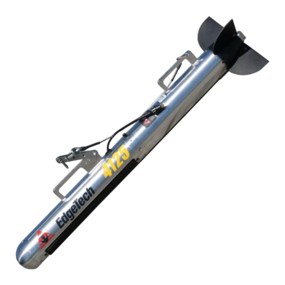
2-13 2.2 4125i Towfish Specifications The specifications for the 4125i Towfish are shown below. SPECIFICATION VALUE Size: 114.8 cm (45.2 in.) long; 9.6 cm (3.75 in.) diameter Weight in air: 20.4 kg (45.0 lbs.) Weight in saltwater: 14.4 kg (31.6 lbs.) -
Page 33: 4125I Towfish Drawings
Pressure sensor working depth: 0–200 m Pressure sensor tolerance: >200 m Navigation interfaces: RS-232, NMEA0183 Keel Weight Kit Depressor Wing Kit Options: Hull Scan Kit Magnetometer Interface Table 2-2: 4205i Towfish Specifications 2.2.1 4125i Towfish Drawings 4125i/4125 SIDE SCAN SONAR SYSTEM 0004823_REV_G... -
Page 34: Figure 2-5: 4125I With Depressor Wing Icd Drawing
2-15 Figure 2-5: 4125i with Depressor Wing ICD Drawing... -
Page 35: Figure 2-6: 0010482, Doc Drawing Icd Ss Array 4125
2-16 Figure 2-6: 0010482, DOC Drawing ICD SS Array 4125... -
Page 36: Figure 2-7 4125 Electronics Bottle
2-17 Figure 2-7 4125 Electronics Bottle... -
Page 37: Cable Drawings
Outline drawings of the supplied cables are listed below, along with their corresponding figure numbers. • 2-8: K IGURE EVLAR EINFORCED ABLE ELEMETRY 2-9: AC P • IGURE OWER ABLE 2-10: DC P • IGURE OWER ABLE 2-11: E • IGURE THERNET ABLE 4125i/4125 SIDE SCAN SONAR SYSTEM 0004823_REV_G... - Page 38 2-19 Figure 2-8: Kevlar Reinforced Tow Cable, Telemetry...
- Page 39 2-20 Figure 2-9: AC Power Cable...
-
Page 40: Figure 2-10: Dc Power Cable For Portable Topside
2-21 Figure 2-10: DC Power Cable for Portable Topside... - Page 41 2-22 Figure 2-11: Ethernet Cable...
-
Page 42: Setup And Activation
3.1 Unpacking and Inspection The towfish is shipped in a foam-lined Pelican Storm Case. The 4125i-P Topside Processor is shipped in a cardboard box with its associated cables, including the tow cable, depending on its length. Before unpacking the system components, inspect the shipping containers for any damage. -
Page 43: Use Of An Uninterrupted Power Supply
Association (NMEA) 0183 message sentence formats from a connected global positioning system (GPS) or integrated navigation system. 3.4 Placement of the Topside Processor The two topside options for the 4125i system have different placement requirements within a vessel, and these are detailed below: 4125i/4125 SIDE SCAN SONAR SYSTEM... -
Page 44: 4125I-P Topside Processor Placement
4125i-P Topside Processor Placement The 4125i-P Topside Processor is designed to be rugged and can be used in an environment prone to mist and sea spray if the cover is kept closed. Otherwise, it should be located and set up in a dry, sheltered area that is protected from weather and water spray, and where the temperature is consistently between 0°–45°C (32°–113°F). -
Page 45: Figure 3-1: 4125-P Topside Processor Side Panel
3-26 POWER 5A/250V TOWCABLE ETHERNET AC INPUT DC INPUT switch connector fuse connector connector connector LINK POWER FISH POWER indicator indicator indicator indicator Figure 3-1: 4125-P Topside Processor Side Panel... -
Page 46: 4125I Rack Mount Topside Controls And Indicators
3-27 The 4125i-P Topside Processor controls and indicators are the following: CONTROL OR INDICATOR DESCRIPTION Power (Switch) Toggle switch. Turns on the 4125i-P Topside Processor. Power (Indicator) Red Indicator. Illuminated when 4125i-P Topside processer is on. Fish Power (Indicator) Red Indicator. Illuminated when the 4125i-P Topside Processor is on. -
Page 47: Figure 3-2: 4125I Rack Mount Front Panel-Controls And Indicators
FISH POWER POWER POWER Indicator Indicator Indicator Indicator switch Figure 3-2: 4125i Rack Mount Front Panel—Controls and Indicators POWER DATA SEA CABLE Connection (to PC) Connection (to fish) Connection & Switch Figure 3-3: 4125i Rack Mount Back Panel—Controls and Connections... -
Page 48: Topside Processor Connections
However, should any of these devices be replaced, or if upgrades are later installed, it may be required that the TCP/IP addresses be reconfigured. In addition, any computer that is to be connected to the 4125i- P Topside Processor must have its IP address set to 192.9.0.nnn, where nnn is any integer from 1 to 100, except for the following reserved addresses: 192.9.0.225... -
Page 49: Assembling The 4125I Towfish
3.9 Installing Optional Equipment This subsection describes how to install some of the 4125i optional equipment. Users that do not have these options, or do not wish to configure their towfish with them at this time, can proceed to sub-section 3.10: C... -
Page 50: Installing The Hull Scan Kit
Installing the Hull Scan Kit The following subsections describe how to install the inverted horizontal and vertical hull scan brackets for the 4125i towfish as described in sub-section 1.2.5.3): 1. Remove the standard tow arm and recovery cable. 2. Attach the bracket to tapped holes on the bottom of towfish for horizontal (inverted) hull... -
Page 51: Figure 3-6: Vertical Hull-Scan Bracket Attached
3. Attach the tow arm to the hull-scan bracket. 4. Attach hull scan recovery cable to hull-scan bracket and tow arm as pictured in 3-7. IGURE 5. Tighten and seize shackles with wire ties or seizing wire. 4125i/4125 SIDE SCAN SONAR SYSTEM 0004823_REV_G... -
Page 52: Installing The Depressor Wing
3-33 Figure 3-7: Connected Towfish (Horizontal Hull-Scan Shown) NOTE: Because the towfish is now inverted, the starboard and port will be reversed in the waterfall display. If desired, the tow fish forward and aft housings can be disassembled, and the port and starboard array connectors reversed so that the hull-scan data appears on the correct side. -
Page 53: Figure 3-8: Depressor Wing Bracket Shown Attached To Tow Fish Bracket
5. Verify that the tow cable connector on the towfish and the connector on the tow cable are free of corrosion or dirt. 6. Apply a thin film of silicone grease to the pins of the tow cable connector on the towfish. 4125i/4125 SIDE SCAN SONAR SYSTEM 0004823_REV_G... -
Page 54: Figure 3-10: Tow Cable Shown Routed Through Depressor Wing Top Hole
3-35 7. Pass the tow cable through the hole on the top of the depressor wing from the top, as shown. Figure 3-10: Tow cable shown Routed through Depressor Wing Top Hole. 8. Connect the tow cable connector to the tow fish connector and secure the connector locking sleeve. -
Page 55: Connecting The System Components
Figure 3-12: Cable grip attached to Depressor Wing Mounting Point. 3.10 Connecting the System Components Most of the system components connect to the 4125i-P or 4125i-RM topsides directly. Optional components, such as a printer, navigation system, and cable counters, connect to the supplied laptop. -
Page 56: Figure 3-13: Towfish With Tow Cable Connected And Attached
To connect and attach the tow cable to the towfish: 1. Verify that the tow cable is not connected to the 4125i Topside Processor. 2. Verify that the tow cable connector on the towfish and the connector on the tow cable are free of corrosion or dirt. -
Page 57: Connecting The Topside
3.10.2.1 Connecting the 4125i-P Topside Processor To connect the 4125i-P Topside Processor: 1. Verify that the 4125i-P Topside Processor is not connected to AC power. 2. Verify that the tow cable is properly connected and attached to the towfish, and then connect the tow cable to the Tow Cable connector. -
Page 58: System Activation And Test
3.11.1 Preparing a Wired Ethernet LAN Connection The wired Ethernet LAN connection is made by connecting the supplied Ethernet cable from the 4125i-P Portable Topside Processor to the laptop computer. If an Ethernet Category 5 cable greater than 10 meters is connected instead, the Network Adapter on the laptop computer should be set to 10 Mbit/s, Full Duplex. -
Page 59: Activating The 4125I Series System
Ethernet LAN is enabled. If the wireless Ethernet connection is being used, verify that the wireless network switch is on and Wireless Networking is enabled. 3. Turn on the Power switch on the side panel of the 4125i-P Topside or the front of the 4125i-RM topside (ensure the rear toggle switch is also on). -
Page 60: Figure 3-14: Discover 4125 Towfish Control Tab
3-41 1. Activate the system as described above. CAUTION! Do not allow the transducer arrays on the towfish to continuously transmit in the air for an extended period as damage to the transducer arrays could occur. 2. In the Discover 4125 Main window, click the Towfish Control tab on the Lower Control panel. This 3-14. -
Page 61: Towfish Deployment
Discover 4125 software under External Device Controls. 3.13 Towfish Deployment The 4125i Towfish can be towed at speeds of up to 4.8 knots while still meeting NOAA and IHO-44S 3-15 specifications of 3 pings on a 1-meter cubed target at 100 meters. Shown in... - Page 62 3-43 CAUTION! The deployment instructions below are only meant as a general guide. Due to varying conditions, exact deployment methods will change, and it is up to the end-user to modify their deployment procedure to match the conditions they are working under. CAUTION! When lowering the towfish in an area where the bottom topography is not known, be careful not to strike the bottom or a...
-
Page 63: Figure 3-17: 4125 Towfish Being Deployed
OWING HARACTERISTICS manual. NOTE 2: For detailed information about the EdgeTech Discover 4125i Side Scan Sonar software, including how to record data, refer to the ISCOVER 4125 S OFTWARE ANUAL NOTE 3: The deployment instructions below assume the deployment testing has been completed, and the towfish is on and transmitting. -
Page 64: Towing Characteristics
The following towfish layback charts are provided to assist in towing. Please consider the following points if they are used: The standard 4125i towfish currently supports depths no greater than 200 meters. • The results listed in these tables are calculated using the Woods Hole WHOI cable program with •... - Page 65 Tow Fish Relative Speed = Tow Vessel Speed - Ocean Current Ex: Tow Vessel Speed - 5kts, Ocean Current 1 kt, ->Tow Fish Relative Speed = 4 kts.; Use the 4 kts. data curve in the graphs listed within. 4125i/4125 SIDE SCAN SONAR SYSTEM 0004823_REV_G...
-
Page 66: Figure 1-1: 4125 Towfish
3-47 Tow Vessel Direction Ocean Current Direction Figure 3-19: Tow Vessel Direction vs. Ocean Current CONFIGURATION # TOWFISH CABLE TYPE LENGTH (M) 4125 23080 (.375” Kevlar) 4125 23080 4125 23080 4125 23080 4125 + 15 lb. Keel Weight 23080 4125 + 15 lb. Keel Weight 23080 4125 + 15 lb. - Page 67 4125 + 15 lb. Keel Weight + Depressor A304874 Wing A320327 4125 (.32” Armored) 4125 A320327 4125 A320327 4125 A320327 4125 A320327 4125 + 15 lb. Keel Weight A320327 4125 + 15 lb. Keel Weight A320327 4125i/4125 SIDE SCAN SONAR SYSTEM 0004823_REV_G...
- Page 68 3-49 CONFIGURATION # TOWFISH CABLE TYPE LENGTH (M) 4125 + 15 lb. Keel Weight A320327 4125 + 15 lb. Keel Weight A320327 4125 + 15 lb. Keel Weight A320327 4125 + Depressor Wing A320327 4125 + Depressor Wing A320327 4125 + Depressor Wing A320327 4125 + Depressor Wing A320327...
-
Page 69: Table 3-5: Towfish Vs. Cable Length Laybacks
4125 + 15 lb. Keel Weight + Depressor A302799 Wing 4125 + 15 lb. Keel Weight + Depressor A302799 Wing 4125 + 15 lb. Keel Weight + Depressor A302799 Wing Table 3-5: Towfish vs. Cable Length Laybacks 4125i/4125 SIDE SCAN SONAR SYSTEM 0004823_REV_G... -
Page 70: Config. 2: 4125I, 23080 Cable - 100M Long
3-51 3.14.1.1 Config. 2: 4125i, 23080 Cable - 100m Long Tow Cable Shape & Tow Fish Position 6 kts 5 kts 4 kts 3 kts Kevlar Tow Cable - p/n 23080, 2 kts Length - 100m Tow Fish - 4125 Telemetry... -
Page 71: Config. 4: 4125I, 23080 Cable - 300M Long
3-52 3.14.1.2 Config. 4: 4125i, 23080 Cable - 300m Long Tow Cable Shape & Tow Fish Position 6 kts 5 kts 4 kts 3 kts Kevlar Tow Cable - p/n 23080, Length - 300m Tow Fish - 4125 Telemetry 2 kts... -
Page 72: Config. 6: 4125I + 15 Lb. Keel Weight, 23080 Cable - 100M Long
3-53 3.14.1.3 Config. 6: 4125i + 15 lb. Keel Weight, 23080 Cable - 100m Long Tow Cable Shape & Tow Fish Position 6 kts 5 kts 4 kts 3 kts Kevlar Tow Cable - p/n 23080, Length - 100m Tow Fish - 4125 Telemetry + 15lbf. Wt. -
Page 73: Config. 8: 4125I + 15 Lb. Keel Weight, 23080 Cable - 300M Long
3-54 3.14.1.4 Config. 8: 4125i + 15 lb. Keel Weight, 23080 Cable - 300m Long Tow Cable Shape & Tow Fish Position 6 kts 5 kts 4 kts 3 kts Kevlar Tow Cable - p/n 23080, Length - 300m -100 Tow Fish - 4125 Telemetry + 15 lbf Wt. -
Page 74: Config. 10: 4125I + Depressor Wing, 23080 Cable - 100M Long
3-55 3.14.1.5 Config. 10: 4125i + Depressor Wing, 23080 Cable - 100m Long Tow Cable Shape & Tow Fish Position 6 kts 5 kts 4 kts 3 kts Kevlar Tow Cable - p/n 23080, Length - 100m Tow Fish - 4125 Telemetry + Depressor... -
Page 75: Config. 12: 4125I + Depressor Wing, 23080 Cable - 300M Long
3-56 3.14.1.6 Config. 12: 4125i + Depressor Wing, 23080 Cable - 300m Long Tow Cable Shape & Tow Fish Position 6 kts 5 kts 4 kts 3 kts Kevlar Tow Cable - p/n 23080, Length - 300m Tow Fish - 4125 Telemetry + Depressor... -
Page 76: Config. 14: 4125I + 15 Lb. Keel Wt. + Depressor Wing, 23080 Cable - 100M
3-57 3.14.1.7 Config. 14: 4125i + 15 lb. Keel Wt. + Depressor Wing, 23080 Cable – 100m Tow Cable Shape & Tow Fish Position 6 kts 5 kts 4 kts 3 kts Kevlar Tow Cable - p/n 23080, Length - 100m Tow Fish - 4125 Telemetry + 15 lbf Wt. -
Page 77: Config. 16: 4125I + 15 Lb. Keel Wt. + Depressor Wing, 23080 Cable - 300M
3-58 3.14.1.8 Config. 16: 4125i + 15 lb. Keel Wt. + Depressor Wing, 23080 Cable – 300m Tow Cable Shape & Tow Fish Position 6 kts 5 kts 4 kts 3 kts Kevlar Tow Cable - p/n 23080, -100 Length - 300m Tow Fish - 4125 Telemetry + 15 lbf Wt. -
Page 78: Config. 18: 4125I, A304874 Cable - 100M Long
3-59 3.14.1.9 Config. 18: 4125i, A304874 Cable - 100m Long Tow Cable Shape & Tow Fish Position 6 kts 5 kts 4 kts 3 kts Tow Cable - p/n A304874, Length - 100m Tow Fish - 4125 Telemetry 2 kts... -
Page 79: Config. 20: 4125I, A304874 Cable - 300M* Long
3-60 3.14.1.10 Config. 20: 4125i, A304874 Cable - 300m* Long Tow Cable Shape & Tow Fish Position 6 kts 5 kts 4 kts -100 3 kts -120 -140 Tow Cable - p/n A304874, Length - 300m Tow Fish - 4125 Telemetry... -
Page 80: Config. 22: 4125I + 15 Lb. Keel Weight, A304874 Cable - 100M Long
3-61 3.14.1.11 Config. 22: 4125i + 15 lb. Keel Weight, A304874 Cable - 100m Long Tow Cable Shape & Tow Fish Position 6 kts 5 kts 4 kts 3 kts Tow Cable - p/n A304874, Length - 100m Tow Fish - 4125 Telemetry + 15 lbf Wt. -
Page 81: Config. 24: 4125I + 15 Lb. Keel Weight, A304874 Cable - 300M* Long
3-62 3.14.1.12 Config. 24: 4125i + 15 lb. Keel Weight, A304874 Cable - 300m* Long Tow Cable Shape & Tow Fish Position 6 kts 5 kts 4 kts -100 -120 3 kts Tow Cable - p/n A304874, Length - 300m -140 Tow Fish - 4125 Telemetry + 15 lbf Wt. -
Page 82: Config. 26: 4125I + Depressor Wing, A304874 Cable - 100M Long
3-63 3.14.1.13 Config. 26: 4125i + Depressor Wing, A304874 Cable - 100m Long Tow Cable Shape & Tow Fish Position 6 kts 5 kts 4 kts 3 kts Tow Cable - p/n A304874, Length - 100m Tow Fish - 4125 Telemetry + Depressor... -
Page 83: Config. 28: 4125I + Depressor Wing, A304874 Cable - 300M* Long
Length - 300m Tow Fish - 4125 Telemetry + Depressor -160 2 kts -180 Cable Length (m) *The maximum length for this type of cable that can be used with the 4125i telemetry system is 250m. 4125i/4125 SIDE SCAN SONAR SYSTEM 0004823_REV_G... -
Page 84: Config. 30: 4125I + 15 Lb. Keel Wt. + Dep. Wing, A304874 Cable - 100M
3-65 3.14.1.15 Config. 30: 4125i + 15 lb. Keel Wt. + Dep. Wing, A304874 Cable - 100m Tow Cable Shape & Tow Fish Position 6 kts 5 kts 4 kts 3 kts 2 kts Tow Cable - p/n A304874, Length - 100m... -
Page 85: Config. 32: 4125I + 15 Lb. Keel Weight + Dep. Wing, A304874 Cable - 300M
Tow Fish - 4125 Telemetry + Depressor -180 + 15 lbf Wt. 2 kts -200 Cable Length (m) *The maximum length for this type of cable that can be used with the 4125i telemetry system is 250m. 4125i/4125 SIDE SCAN SONAR SYSTEM 0004823_REV_G... -
Page 86: Config. 34: 4125I, A320327 Cable - 100M Long
3-67 3.14.1.17 Config. 34: 4125i, A320327 Cable - 100m Long Tow Cable Shape & Tow Fish Position 6 kts 5 kts 4 kts 3 kts Tow Cable - p/n A320327, Length - 100m Tow Fish - 4125 Telemetry 2 kts... -
Page 87: Config. 37: 4125I, A320327 Cable - 400M Long
3-68 3.14.1.18 Config. 37: 4125i, A320327 Cable - 400m Long Tow Cable Shape & Tow Fish Position 6 kts -100 5 kts 4 kts -150 3 kts Tow Cable - p/n A320327, Length - 400m Tow Fish - 4125 Telemetry... -
Page 88: Config. 39: 4125I + 15 Lb. Keel Weight, A320327 Cable - 100M Long
3-69 3.14.1.19 Config. 39: 4125i + 15 lb. Keel Weight, A320327 Cable - 100m Long Tow Cable Shape & Tow Fish Position 6 kts 5 kts 4 kts 3 kts Tow Cable - p/n A320327, Length - 100m Tow Fish - 4125 Telemetry + 15 lbf Wt. -
Page 89: Config. 42: 4125I + 15 Lb. Keel Weight, A320327 Cable - 400M Long
3-70 3.14.1.20 Config. 42: 4125i + 15 lb. Keel Weight, A320327 Cable - 400m Long Tow Cable Shape & Tow Fish Position 6 kts -100 5 kts 4 kts -150 3 kts Tow Cable - p/n A320327, Length - 400m Tow Fish - 4125 Telemetry + 15 lbf Wt. -
Page 90: Config. 44: 4125I + Depressor Wing, A320327 Cable - 100M Long
3-71 3.14.1.21 Config. 44: 4125i + Depressor Wing, A320327 Cable - 100m Long Tow Cable Shape & Tow Fish Position 6 kts 5 kts 4 kts 3 kts Tow Cable - p/n A320327, Length - 100m Tow Fish - 4125 Telemetry + Depressor... -
Page 91: Config. 47: 4125I + Depressor Wing, A320327 Cable - 400M Long
3-72 3.14.1.22 Config. 47: 4125i + Depressor Wing, A320327 Cable - 400m Long Tow Cable Shape & Tow Fish Position 6 kts -100 5 kts 4 kts -150 Tow Cable - p/n A320327, 3 kts Length - 400m Tow Fish - 4125 Telemetry + Depressor... -
Page 92: Config. 49: 4125I + 15 Lb. Keel Wt. + Dep. Wing, A320327 Cable - 100M
3-73 3.14.1.23 Config. 49: 4125i + 15 lb. Keel Wt. + Dep. Wing, A320327 Cable – 100m Tow Cable Shape & Tow Fish Position 6 kts 5 kts 4 kts 3 kts Tow Cable - p/n A320327, Length - 100m Tow Fish - 4125 Telemetry + Depressor + 15lbf Wt. -
Page 93: Config. 52: 4125I + 15 Lb. Keel Wt. + Dep. Wing, A320327 Cable - 400M
3-74 3.14.1.24 Config. 52: 4125i + 15 lb. Keel Wt. + Dep. Wing, A320327 Cable - 400m Tow Cable Shape & Tow Fish Position 6 kts -100 5 kts 4 kts -150 3 kts Tow Cable - p/n A320327, Length - 400m... -
Page 94: Config. 54: 4125I, A302799 Cable - 100M Long
3-75 3.14.1.25 Config. 54: 4125i, A302799 Cable - 100m Long Tow Cable Shape & Tow Fish Position 6 kts 5 kts 4 kts 3 kts Tow Cable - p/n A302799, Length - 100m 2 kts Tow Fish - 4125 Telemetry... -
Page 95: Config. 57: 4125I, A302799 Cable - 400M Long
3-76 3.14.1.26 Config. 57: 4125i, A302799 Cable - 400m Long Tow Cable Shape & Tow Fish Position 6 kts -100 5 kts 4 kts -150 3 kts Tow Cable - p/n A302799, -200 Length - 400m Tow Fish - 4125 Telemetry... -
Page 96: Config. 59: 4125I, A302799 Cable - 600M Long
3-77 3.14.1.27 Config. 59: 4125i, A302799 Cable - 600m Long Tow Cable Shape & Tow Fish Position -100 6 kts -150 5 kts 4 kts -200 -250 3 kts Tow Cable - p/n A302799, -300 Length - 600m Tow Fish - 4125 Telemetry... -
Page 97: Config. 61: 4125I + 15 Lb. Keel Weight, A302799 Cable - 100M Long
3-78 3.14.1.28 Config. 61: 4125i + 15 lb. Keel Weight, A302799 Cable - 100m Long Tow Cable Shape & Tow Fish Position 6 kts 5 kts 4 kts 3 kts Tow Cable - p/n A302799, Length - 100m Tow Fish - 4125 Telemetry + 15 lbf Wt. -
Page 98: Config. 64: 4125I + 15 Lb. Keel Weight, A302799 Cable - 400M Long
3-79 3.14.1.29 Config. 64: 4125i + 15 lb. Keel Weight, A302799 Cable - 400m Long Tow Cable Shape & Tow Fish Position 6 kts -100 5 kts 4 kts -150 3 kts Tow Cable - p/n A302799, -200 Length - 400m Tow Fish - 4125 Telemetry + 15 lbf Wt. -
Page 99: Config. 66: 4125I + 15 Lb. Keel Weight, A302799 Cable - 600M Long
3-80 3.14.1.30 Config. 66: 4125i + 15 lb. Keel Weight, A302799 Cable - 600m Long Tow Cable Shape & Tow Fish Position -100 6 kts -150 5 kts 4 kts -200 -250 3 kts Tow Cable - p/n A302799, Length - 600m -300 Tow Fish - 4125 Telemetry + 15 lbf Wt. -
Page 100: Config. 68: 4125I + Depressor Wing, A302799 Cable - 100M Long
3-81 3.14.1.31 Config. 68: 4125i + Depressor Wing, A302799 Cable - 100m Long Tow Cable Shape & Tow Fish Position 6 kts 5 kts 4 kts 3 kts Tow Cable - p/n A302799, Length - 100m Tow Fish - 4125 Telemetry + Depressor... -
Page 101: Config. 71: 4125I + Depressor Wing, A302799 Cable - 400M Long
3-82 3.14.1.32 Config. 71: 4125i + Depressor Wing, A302799 Cable - 400m Long Tow Cable Shape & Tow Fish Position 6 kts -100 5 kts 4 kts -150 3 kts Tow Cable - p/n A302799, -200 Length - 400m Tow Fish - 4125 Telemetry + Depressor... -
Page 102: Config. 73: 4125I + Depressor Wing, A302799 Cable - 600M Long
3-83 3.14.1.33 Config. 73: 4125i + Depressor Wing, A302799 Cable - 600m Long Tow Cable Shape & Tow Fish Position -100 6 kts -150 5 kts -200 4 kts -250 3 kts Tow Cable - p/n A302799, Length - 600m... -
Page 103: Config. 75: 4125I + 15 Lb. Keel Wt. + Dep. Wing, A302799 Cable - 100M
3-84 3.14.1.34 Config. 75: 4125i + 15 lb. Keel Wt. + Dep. Wing, A302799 Cable – 100m Tow Cable Shape & Tow Fish Position 6 kts 5 kts 4 kts 3 kts Tow Cable - p/n A302799, Length - 100m Tow Fish - 4125 Telemetry + Depressor + 15 lbf Wt. -
Page 104: Config. 78: 4125I + 15 Lb. Keel Wt. + Dep. Wing, A302799 Cable - 400M
3-85 3.14.1.35 Config. 78: 4125i + 15 lb. Keel Wt. + Dep. Wing, A302799 Cable - 400m Tow Cable Shape & Tow Fish Position 6 kts -100 5 kts 4 kts -150 3 kts Tow Cable - p/n A302799, -200... -
Page 105: Config. 80: 4125I + 15 Lb. Keel Weight + Dep. Wing, A302799 Cable - 600M
3-86 3.14.1.36 Config. 80: 4125i + 15 lb. Keel Weight + Dep. Wing, A302799 Cable - 600m Tow Cable Shape & Tow Fish Position -100 6 kts -150 5 kts -200 4 kts -250 3 kts Tow Cable - p/n A302799,... -
Page 106: Towfish Recovery
3-87 3.15 Towfish Recovery CAUTION! The following procedure is only meant as a general guide. Due to varying conditions, exact recovery methods will change, and it is up to the end-user to modify their procedure to match the conditions they are working under. -
Page 107: Maintenance
4.1 Cleaning the 4125i System The 4125i-P and 4125i-RM Topsides require minimal maintenance. However, the Tow Cable / Sea Cable connector should be periodically lubricated, and the other connectors should be inspected regularly. -
Page 108: Rearming The Towfish
4-89 opening of each female socket. Use only a small amount, as packing too much grease will cause a hydraulic lock, preventing the connectors from being properly mated. NOTE: Remember to always install dummy connectors on the connectors of the tow cable and the towfish tow cable connector. 4.2 Rearming the Towfish Should the shear pin snap, it must be replaced. -
Page 109: Troubleshooting
Turn off the topside processor and disconnect the tow cable before disassembling the towfish. CAUTION! Opening the electronics chassis may void the user’s warranty unless preapproved by EdgeTech. Contact EdgeTech Customer Service before opening the chassis. 5.2.1 Disassembly To disassemble the towfish: 1. -
Page 110: Figure 5-1: Towfish Parts Of Note
5-91 Electronics bottle section Transducer array section Screw (8) Figure 5-1: Towfish Parts of Note 3. Pull the two sections apart far enough to be able to access the connectors inside. NOTE: Separating the two halves further than needed will make reassembly difficult Figure 5-2: Electronics Bottle and Transducer Array Sections Separated... -
Page 111: Figure 5-3: Cables Disconnected From The Electronics Bottle
Figure 5-3: Cables Disconnected from the Electronics Bottle 5. Remove the two Phillips head screws from the electronics bottle. These screws are located under the “Void if Removed” labels. Figure 5-4: Removing the Phillips Head Screws from the Electronics Bottle 4125i/4125 SIDE SCAN SONAR SYSTEM 0004823_REV_G... -
Page 112: Figure 5-5: Removing The Electronics Chassis From The Electronics Bottle
5-93 6. Remove the electronics chassis from the electronics bottle by pulling the electronics bottle connector end cap straight out, as shown in 5-4. IGURE NOTE: The use of locking sleeves attached to the connectors will aid in removal. Contact for instructions on USTOMER ERVICE... -
Page 113: Reassembly
To reassemble the towfish, reverse the disassembly procedure. 5.3 Calibrating the Compass The compass is calibrated at the EdgeTech manufacturing facility. Should the compass in the towfish lose its calibration for any reason in the field, it may be necessary to recalibrate it. This is accomplished by accessing the Towfish’s embedded Windows installation with the Windows Remote Desktop Application... -
Page 114: Figure 5-7: Remote Desktop Splash Screen
5-95 Figure 5-7: Remote Desktop Splash Screen 3. If a warning pops up, as shown in 5-8, click Yes before proceeding. IGURE Figure 5-8: Remote Desktop Warning Screen... -
Page 115: Figure 5-9: Closing Sonar.exe
Shut down the Sonar.exe application running (see below): IGURE Figure 5-9: Closing Sonar.exe 5. On this desktop, click on the Tera Term command console icon 5-10). At the splash screen IGURE 5-11), click OK. IGURE Figure 5-10: Tera Term Icon 4125i/4125 SIDE SCAN SONAR SYSTEM 0004823_REV_G... -
Page 116: Figure 5-11: Tera Term Splash Screen
5-97 Figure 5-11: Tera Term Splash Screen... -
Page 117: Figure 5-12. Terra Term Port Set-Up
5-98 6. Establish communications with the SSAHRS and verify via a serial console. Figure 5-12. Terra Term Port Set-up Figure 5-13. Motion Sensor Serial Output 4125i/4125 SIDE SCAN SONAR SYSTEM 0004823_REV_G... -
Page 118: Figure 5-14. Motion Sensor Calibration Result
5-99 7. Stop the device and retrieve the current level 2 (factory) calibration using the following two commands. stop <CR> getLevel2CompassCalibration <CR> 8. Ensure that the points are 0, the error percentage is 100.0%, the hard iron values are all 0.0, and that the soft iron values are an identity matrix (see 5-14). -
Page 119: Figure 5-15. Motion Sensor Serial Output
10. Slowly move the vehicle around in such a fashion as to position the compass in as many possible orientations as possible for pitch, roll, and heading directions. a. UUT in a neutral position: Pitch/Roll ~0 degrees, rotate device thru 360 degrees of heading (10 times) Figure 5-16: Tilt 0 degrees 4125i/4125 SIDE SCAN SONAR SYSTEM 0004823_REV_G... -
Page 120: Figure 5-17: Tilt -90 Degrees
5-101 b. UUT in Pitch/Roll ~-90 degrees rotate device thru 360 degrees of heading (10 times) Figure 5-17: Tilt -90 degrees c. UUT in Pitch/Roll ~+90 degrees rotate device thru 360 degrees of heading (10 times) Figure 5-18: Tilt +90 degrees 11. -
Page 121: Changing The Angle Of Declination
Changing the Angle of Declination The compass angle of declination is set to true north at the EdgeTech facility. However, to provide a more accurate target location, it is necessary to enter the known magnetic declination for the survey location into the compass as follows: 1. -
Page 122: Figure 5-20: Declination Information In Terra Term Vt
5-103 Figure 5-20: Declination Information in Terra Term VT 2. Verify current Declination Angle of Deviation using the following command: getDeclination <CR> Figure 5-21: Using the getDeclination Command in Terra Term VT 3. Enter the set declination command to get help for command:... -
Page 123: Figure 5-22: Magnetic Declination Estimated Value Screen
Here is an example of how using this website can help you to determine your angle of deviation: • Zipcode 02360 was inserted, then “Get & Add Lat/Lon” was selected: Figure 5-22: Magnetic Declination Estimated Value Screen 4125i/4125 SIDE SCAN SONAR SYSTEM 0004823_REV_G... -
Page 124: Figure 5-23: Angle Of Declination Calculated
5-105 • “Calculate” is then selected: Figure 5-23: Angle of Declination Calculated The Declination Angle received was 14.47 degrees. This is the angle that will be entered • into the TeraTerm command screen. 4. Enter the Declination Angle using the command: setDeclination, 14.47 <CR>... -
Page 125: General Troubleshooting
Should some operational or performance problems occur with the 4125 Series Dual-frequency Side Scan Sonar System, it may be possible to correct them using the troubleshooting guides in the following pages. 5-1, and For the 4125i-P Topside Processor, a tabular troubleshooting guide is provided in ABLE ABLE for the towfish. -
Page 126: 4125I-P Topside Processor Troubleshooting
Verify that all the cables on the topside processor and the towfish are mated and are not loose or damaged. Most causes of operational or performance problems are a result of poor connections. 5.5 4125i-P Topside Processor Troubleshooting SYMPTOM PROBABLE CAUSE... - Page 127 Check for other sources of noise. Try an alternate survey area. of noise Distortion or noise in the Tow fins are data damaged or Inspect and replace if needed. missing Excess strumming of Inspect and remove slack from cable. tow cable 4125i/4125 SIDE SCAN SONAR SYSTEM 0004823_REV_G...
-
Page 128: Table 5-2: 4125I Towfish Troubleshooting Guide
Delete the incorrect file and re-open and reconfigure Discover. used .jni file No Depth Display A clogged or Clean depth sensor port with low-pressure air. faulty depth To replace the sensor, Contact CUSTOMER SERVICE. sensor Table 5-2: 4125i Towfish Troubleshooting Guide... -
Page 129: Tow Cable Inspection
Inspect whether any part of cable was bent beyond the allowable radius. The minimum bending radius of tow cable used with the 4125i Series Dual-frequency Side Scan Sonar System is 6 inches. The cable may suffer damage when the cable is wound or twisted with less than this radius. -
Page 130: Locating An Open Conductor
5-111 The distance to the short from end #1 is the ratio of R1/(R1+R2) times the total cable length. Recheck from end #2 that is R2/(R1+R2) times the cable length. 5.7.2 Locating an Open Conductor An open conductor in a tow cable is much more difficult to locate than a short. Therefore, a capacitance bridge is recommended to diagnose this problem. -
Page 131: System Restore
13. Remove the USB3 flash drive and restart the topside. 14. Re-boot and click on the Windows icon and navigate to Control Panel > System. Activate Windows using the supplied key code on the rear of the laptop. 4125i/4125 SIDE SCAN SONAR SYSTEM 0004823_REV_G... -
Page 132: Printers
Ultra 120 • • Ultra 120-HD Ultra 200 HD • EPC 1086 • • EPC 1086 Old Geoprinter 975 • TDU 850 • NOTE: EdgeTech Topsides support the Ethernet-only Printers listed above. Consult manufacturer’s operating manual printer requirements and set up. -
Page 133: 4125I And 4125 Spare Kits
5-114 5.10 4125i AND 4125 SPARE KITS 0022465 ASSY TOP KIT SPARES 4125I-P PORTABLE TOPSIDE PROCESSOR Part Description 0019821 PCB ASSY TOP POWER BOARD 4125P W/ CONTROLLER 0007469 POWER SUPPLY CHASSIS SW AC-DC 88-264 INPUT 24 OUTPUT 13A 312W 0016569... - Page 134 5-115 0022466 ASSY TOP KIT SPARES 4125I 400/900 KHZ TOW FISH PART Description PCB ASSY SUB SONAR ACQUISITION INTERFACE BOARD USB AND DUAL 0013107 LVDS INTERFACE SAIBU 2205 PROGTEST 0016420 PCB ASSY TOP MAIN CSMB3 4125 400-900 KHZ 0022409 ASSY SUB VDSL ETHERNET EXTENSION 4125i...
-
Page 135: Table 5-5: 4125I 400/900 Khz Towfish Spares Kit
5-116 0022466 ASSY TOP KIT SPARES 4125I 400/900 KHZ TOW FISH CONN INLINE 2MM HOUSING 10 POS FEMALE ROHS MILLI-GRID DOUBLE 0003971 ROW POLARIZED 0004188 CONTACT FEMALE CRIMP 24-30 AWG GOLD ROHS MILLI-GRID Table 5-5: 4125i 400/900 kHz Towfish Spares Kit... -
Page 136: Table 5-6: 4125I 600/1600 Khz Towfish Spares Kit
5-117 0022467 ASSY TOP KIT SPARES 4125I 600/1600 KHZ TOW FISH 0014871 BRACKET SUPPORT 4125 CSMB2 AL 0022463 DOC FAT ELECTRONICS HOUSING 4125i LT MEMORY FLASH GENERIC WITH COMPASS R-DRIVE IMAGE KONTRON 0023032 E38XX CPU 0021177 SOFTWARE EDGETECH FOLDER 4125 TOW FISH SONAR2... -
Page 137: Table 5-7: 4125 Electronics 400-900 Khz Spares Kit
DOC FAT 4125 SONARPRO ELECTRONICS ETHERNET / LT 0016184 ASSY SUB CABLE 4125 USB TO ENET 0021177 SOFTWARE EDGETECH FOLDER 4125 TOW FISH SONAR2 MEMORY FLASH GENERIC WITH COMPASS R-DRIVE IMAGE KONTRON 0023032 E38XX CPU Table 5-7: 4125 Electronics 400-900 kHz Spares Kit... -
Page 138: Table 5-8: 4125 Electronics 4125 600-1600 Khz Spares Kit
0015618 DOC FAT 4125 SONARPRO ELECTRONICS ETHERNET / LT 0016184 ASSY SUB CABLE 4125 USB TO ENET 0021177 SOFTWARE EDGETECH FOLDER 4125 TOW FISH SONAR2 MEMORY FLASH GENERIC WITH COMPASS R-DRIVE IMAGE KONTRON 0023032 E38XX CPU 0007548 BRACKET COMPASS 4125 AL... -
Page 139: Table 5-9: 4125 Lt Electronics 400-900 Khz Spares Kit
0014871 BRACKET SUPPORT 4125 CSMB2 AL 0015618 DOC FAT 4125 SONARPRO ELECTRONICS ETHERNET / LT 0021177 SOFTWARE EDGETECH FOLDER 4125 TOW FISH SONAR2 MEMORY FLASH GENERIC WITH COMPASS R-DRIVE IMAGE KONTRON 0023032 E38XX CPU 0007188 HARDWARE WASHER STD INTERNAL TOOTH LOCK 08 400 SS 0005471 HARDWARE SCREW STD MACHINE PAN HD PHILLIPS 8-32 0.25 INCH 18-8 SS... -
Page 140: Table 5-10: 4125 Lt Electronics 600-1600 Khz Spares Kit
BRACKET SUPPORT 4125 CSMB2 AL 0015618 DOC FAT 4125 SONARPRO ELECTRONICS ETHERNET / LT 0021177 SOFTWARE EDGETECH FOLDER 4125 TOW FISH SONAR2 MEMORY FLASH GENERIC WITH COMPASS R-DRIVE IMAGE KONTRON 0023032 E38XX CPU Table 5-10: 4125 LT Electronics 600-1600 KHZ Spares Kit...
Need help?
Do you have a question about the 4125I and is the answer not in the manual?
Questions and answers