
Related Manuals for Edgetech 4600


Summary of Contents for Edgetech 4600
- Page 1 4 Little Brook Road West Wareham, MA 02576 Tel: (508) 291-0057 Fax: (508) 290-2491 4600 Swath Bathymetry and Side Scan Sonar Reference Manual Document No. 0012885 Email: info@edgetech.com REV G Website: http://www.edgetech.com FEB 2013...
- Page 3 EdgeTech. Any reproduction of EdgeTech supplied software or file sharing is strictly prohibited.
- Page 5 4600 Swath Bathymetry and Side Scan Sonar Warning—Read This First! All personnel involved with the installation, operation or maintenance of the equipment described in this manual should read and understand the warnings and recommendations provided below. Static Sensitive Devices This equipment contains devices that are extremely sensitive to static electrical charges.
-
Page 7: Preface
Preface We, the employees at EdgeTech, would like to thank you for purchasing a 4600 Swath Bathymetry and Side Scan Sonar System. At EdgeTech it is our policy to provide high quality, cost effective products and support services that meet or exceed your requirements, to deliver them on time and to continuously look for ways to improve them. -
Page 8: Warnings, Cautions And Notes
4600 Swath Bathymetry and Side Scan Sonar Warnings, Cautions and Notes Where applicable, warnings, cautions and notes are provided in this manual as follows: WARNING Identifies a potential hazard that could cause personal injury or death to yourself or to others. -
Page 9: Liability
4600 Swath Bathymetry and Side Scan Sonar Liability EdgeTech has made every effort to document in this manual the 4600 Swath Bathymetry and Side Scan Sonar System accurately and completely. However, EdgeTech assumes no liability for errors or for any damages that result from the use of this manual or the equipment it documents. -
Page 10: Warranty
All equipment manufactured by EdgeTech is warranted against defective components and workmanship for a period of one year after shipment. Warranty repair will be done by EdgeTech, free of charge. Shipping costs are to be borne by the customer. Malfunction due to improper use is not covered in the warranty and EdgeTech disclaims any liability for consequential damage resulting from defects in the performance of the equipment. -
Page 11: Warning
4600 Swath Bathymetry and Side Scan Sonar Warning This equipment contains static sensitive devices that are extremely sensitive to static electrical charges, which may be developed on the body and the clothing. Extreme care should be taken when handling these devices both in and out of the circuit board. -
Page 12: Software Service Agreement
Furthermore, EdgeTech software upgrades are meant for the sole use of EdgeTech customers that have purchased a system within a year or have an existing SSA. Any reproduction of EdgeTech supplied software or file sharing is strictly prohibited. -
Page 13: Software Telephone, Facsimile And E-Mail Support
Side Scan Sonar Software Telephone, Facsimile and E-mail Support The SSA entitles EdgeTech customers to contact EdgeTech Customer Service by telephone, facsimile or e-mail to report a difficulty, to discuss a problem or to receive advice on the best way to perform a task. When contacted,... -
Page 14: Returned Material Authorization
Authorization (RMA) number is required prior to returning any equipment to EdgeTech. This is to assist EdgeTech in recognizing the returned equipment when it arrives at EdgeTech’s receiving dock, and to assist customer service representatives in tracking the returned equipment while it is at EdgeTech’s facilities. - Page 15 DHL, UPS, Airborne, etc. 5. If the equipment is the property of EdgeTech (formerly EG&G Marine Instruments Division) please insure for full value. 6. Fax one invoice, packing list, and a copy of the airway bill to EdgeTech upon shipment.
-
Page 16: Customer Service
Side Scan Sonar Customer Service Customer service personnel at EdgeTech are always eager to hear from users of our products. Your feedback is welcome and is a valuable source of information which we use to continually improve these products. Therefore we encourage you to contact customer service to offer any suggestions or to request technical support. -
Page 19: Table Of Contents
Optional Equipment ..................3 Software Description ..................6 System Description ..................7 2.1 The 4600 Sonar Head ..................7 2.1.1 Sonar Processor ..................8 2.1.2 Sonar Arrays ..................8 2.1.3 Sound Velocity Sensor ................ - Page 20 4600 Swath Bathymetry and Side Scan Sonar 2.2.1 The 4600 Topside Sonar Interface ............... 9 2.2.2 The 4600 Topside Processor ..............10 Deck Cable ....................10 Product Specifications ................. 11 System Formats and Connections ..............13 ...
- Page 21 4600 Swath Bathymetry and Side Scan Sonar Appendix B ......................1 Performing a Rub Test ................... 1 Appendix C ......................1 Hardware Data Flow Diagram .................. 1 Sonar Interface Box Connections ................2 Bow Mount Example ....................3 ...
-
Page 23: Introduction
Current efforts are focused on the application of cutting edge chirp, DSP, and acoustic technology. 1.2 Product Overview EdgeTech’s 4600 is a combined, fully-integrated, swath bathymetry and side scan sonar system. The 4600 uses eight receive element transducers and one discrete transmit element to produce real-time, high-resolution, 3D maps of the seafloor, while also providing co-registered simultaneous side scan and bathymetric data. -
Page 24: Supplied Components
4600 Swath Bathymetry and Side Scan Sonar The 4600 operates at one of two frequencies, 230 kHz or 540 kHz, depending on the model. The sonar electronics and arrays are mounted onto a streamline body that is deployed over-the-bow (-or side) of a survey vessel. Sonar data is transferred from the transceiver to the processing unit on board, via an Ethernet network interface. -
Page 25: Optional Equipment
4600 Swath Bathymetry and Side Scan Sonar 1.4 Optional Equipment 4600 Mounting Pole (see drawing in Figure 2 on Page 4) Crescent VS111 Series Hemisphere GPS (Figure 3, Page 5) SMC IMU Sensor (Figure 4, Page 5) ... - Page 26 4600 Swath Bathymetry and Side Scan Sonar Optional Mounting Pole Example: Cable Path Protected by Fairing Max Cable Length = 20 m (65 ft) Ø 10 cm (4 in) 1.02 m (3 ft) 10 cm (4 in) Bow of Survey Vessel 2.1 m (7 ft)
- Page 27 4600 Swath Bathymetry and Side Scan Sonar Optional Dual-Headed GPS System Figure 3: Crescent VS111 Series Hemisphere GPS Optional Motion Reference Unit Figure 4: SMC IMU Sensor Please contact EdgeTech for further product and purchasing information. 4600 R REV G EFERENCE ANUAL...
-
Page 28: Software Description
The data is presented on a color waterfall display and is stored in JSF formats on the hard disk of the Topside Processor. (See Chapter 5, Section 2 for more information about Discover 4600) ® ... -
Page 29: System Description
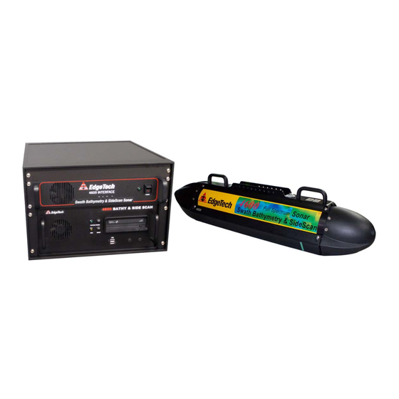
Side Scan Sonar 2. System Description The complete 4600 system consists of a Swath Bathymetry and Side Scan Sonar Head and a Topside Processing Unit. This section describes the two main components that make up the 4600 system and lists its specifications. -
Page 30: Sonar Processor
2.1.3 Sound Velocity Sensor The 4600 Sonar Head has a flooded section in the front that is used to house an OEM version of the AML SV-Xchange sound velocity sensor (SVS) with a 33 mm (1.3 in) x 246 mm (9.5 in) sensor providing a response time of 47 μs, a resolution of 0.001... -
Page 31: Mounting Bracket
Side Scan Sonar 2.1.5 Mounting Bracket The 4600 Mounting Bracket provides the user with an efficient way to carry the system via the two handles at the front and back of the Sonar Head. It also offers a way for the user to secure the 4600 to their deployment mechanism while protecting the 20 m deck cable. -
Page 32: The 4600 Topside Processor
TIA 568-B and is suitable for 10Base-T and 100Base-T. The deck cable is also terminated with a Seacon MINK19-CCP dry mate connector on both ends, has a breaking strength of 545 kg (1200 lbs), and provides power and telemetry to the 4600 system. 4600 R REV G... -
Page 33: Product Specifications
4600 Swath Bathymetry and Side Scan Sonar 2.4 Product Specifications 230 kHz Model 540 kHz Model Physicals Size : 1210 L x 260 W x 230 H (mm) 1210 L x 260 W x 230 H (mm) 47.64 L x 10.13 W x 9.18 H (in) 47.64 L x 10.13 W x 9.18 H (in) - Page 34 4600 Swath Bathymetry and Side Scan Sonar Topside Interface Interface : 100 baseT Ethernet 100 baseT Ethernet Serial RS-232 Serial RS-232 Power Supply : 110/220 VAC Auto-Sensing 110/220 VAC Auto-Sensing Topside Processor Operating System : Windows 7 Windows 7 Interface...
-
Page 35: System Formats And Connections
3.1 Data Formats In order to collect valid survey data, the following is required to support the survey operations and correct processing of the 4600 Bathymetry and Side Scan echo data: a. GPS Position in NMEA format, latitude and longitude b. -
Page 36: System Connections And Data Flow
Side Scan Sonar 3.2 System Connections and Data Flow 3.2.1 Ethernet LAN Connections The Ethernet LAN connection from the Sonar Head to the 4600 Topside Interface is made using a physical wired connection via the standard 20 m deck cable. This cable is fixed to the Sonar Head and provides a Seacon 19 pin connector for direct connection from the Sonar Head to the 4600 Sonar Interface. - Page 37 (Optional) Sonar Processor COM4 Keyboard Track Ball 4600 Sonar Head IP Address: 192.9.0.101 Bathy/Side Scan Arrays (Port and Stbd) Figure 8: Hardware Data Flow Diagram for the 4600 System Figure 9: Sonar Interface Connections 4600 R REV G EFERENCE ANUAL...
- Page 38 4600 Swath Bathymetry and Side Scan Sonar In Figure 8, the 4600 Sonar Interface connects to the Sonar Head via the Seaconn 19 pin connector and Deck Cable. Navigation, heading, roll, pitch, and heave data from the supporting sensors via COM ports 1, 2, and/or 3, are inputted at the Sonar Interface, passed through the Deck Cable, and logged by the Sonar Processor in the Sonar Head.
-
Page 39: Sonar Data Flow
Processor Figure 10: Sonar Data Flow As demonstrated by the flow chart, the 4600 Sonar Interface acquires the heading, position (latitude/longitude), and motion (roll, pitch, and heave) data and relays this information to the 4600 Sonar Head via the Deck Cable. - Page 40 4600 Swath Bathymetry and Side Scan Sonar DISCOVER intakes the raw sonar data and sends it to the Bathymetry Processor, where the raw data is converted to range and angle data. The Bathymetry Processor transmits this range/angle data back to DISCOVER, where it is then displayed on the monitor, packaged with the heading, position, motion, and side scan data, and recorded as a *.JSF file.
-
Page 41: System Assembly And Installation
Again, if any damage is found, please report it to the carrier and to EdgeTech immediately. If any items are missing, please contact EdgeTech using the information provided on page x. - Page 42 Allen wrench. Ensure the connectors are facing the tail section (opposite of the SVS section). The Port and Starboard Arrays are identical but usually EdgeTech designates the array with the lowest serial number as the Port Array. The serial number can be found on the color coded plate in the front of the array (opposite of the connectors).
- Page 43 4600 Swath Bathymetry and Side Scan Sonar couples to the port array’s receivers via the Seacon 19 pin female connector (MINK19-CCP). Port Starboard Figure 12: Sonar Processor Connections on End-Cap 5. Orient the Mounting Bracket on top of the Sonar Processor so that the longest part of the keyway is pointing towards the tail section as shown in Figure 13.
- Page 44 4600 Swath Bathymetry and Side Scan Sonar 7. Ensure the Deck Cable stays within the slotted region of the keyway on the Mounting Bracket and pull the cable towards the tail section (Figure 14). 8. Connect the Deck Cable to the Sonar Processor using the Seacon 16 pin female connector (MINK16-CCP) to J1, as indicated in Figure 12 and Figure 14.
-
Page 45: Positioning The Topside Processing Unit
ON position. 5. Position and secure a MRU to the vessel’s center of motion. If the mounting pole was purchased from EdgeTech, an alternative way to attach the MRU is to the top of this mounting pole. - Page 46 Side Scan Sonar 7. Setup the GPS as described in the GPS’s user manual. 8. Connect the Sonar Head to the 4600 Topside Interface via the Seaconn 19 pin connector. 9. Connect the dual headed GPS to COM1 and the MRU to COM2 (or vice versa).
-
Page 47: Sonar Head Installation
The Sonar Head can be mounted on the side of a vessel, but it is recommended to secure the 4600 to the bow of the boat. Consideration must be given to keel clearance for both cases. This section outlines the 4600 Sonar Head deployment options. -
Page 48: Over-The-Side Deployment
4600 Swath Bathymetry and Side Scan Sonar 4.6.2 Over-the-Side Deployment An alternative to the latter is to mount the 4600 Sonar Head over the side of the survey vessel. An example of an over-the-side deployment is illustrated in the images in Figure 16. A larger representation of these photographs is given in the Appendix on page B2. -
Page 49: Care And Maintenance
Side Scan Sonar 4.6 Care and Maintenance The 4600 System was not designed for long term deployments and it is not recommended to keep the system in water for more than two weeks. After each mission the system should be rinsed thoroughly with freshwater, making sure to rinse the SVS at the front and connectors at the back using the provided rinse holes in the nose and tail cones. - Page 50 4600 Swath Bathymetry and Side Scan Sonar 4600 R REV G EFERENCE ANUAL...
-
Page 51: Principles Of Operation
4600 Swath Bathymetry and Side Scan Sonar Principles of Operation This section describes how to operate the 4600 system in order to collect data with DISCOVER and your third party topside interface. 5.1 Confirming Supporting Data is Present To ensure the Sonar Head’s processing unit is communicating properly with the Topside Processor, follow these steps. - Page 52 4600 Swath Bathymetry and Side Scan Sonar 3. Check each COM port in the drop down menu to ensure data is coming through for each device and in the correct format (Figure 18). a. COM1 = MRU a. COM2 = GPS b.
- Page 53 4600 Swath Bathymetry and Side Scan Sonar Figure 18: Serial Port Information Window 4600 R REV G EFERENCE ANUAL...
- Page 54 4600 Swath Bathymetry and Side Scan Sonar Figure 19: System Status Window 4600 R REV G EFERENCE ANUAL...
-
Page 55: Discover 4600
This section describes DISCOVER and the BATHYMETRIC PROCESSOR entirely and how to operate them during a survey. 1. Launch DISCOVER 4600 using the Desktop shortcut. The two main windows will appear as in Figure 20. Figure 20: DISCOVER Main Window and BATHYMETRIC PROCESSOR... - Page 56 Please refrain from pressing the “x” on the BATHYMETRIC PROCESSOR window. 2. If the EdgeTech 4600 is powered on and connected to the 4600 Topside Interface box, then ensure that the Sonar Head is connected to DISCOVER by ensuring the network is on (NET: ON) down in the right hand corner of the DISCOVER main window (as pointed to by the blue arrow in Figure 22).
- Page 57 DISCOVER Control Menu on the Disk Tab. v. Sonar On – Toggles the 4600 System On/Off. This feature can also be found under the DISCOVER Control Menu on the Towfish Control Tab. vi. Normalize Data – Normalizes the side scan data with respect to the highest intensity.
- Page 58 4600 Swath Bathymetry and Side-Scan Sonar x. Auto Set TVG – Automatically sets the Time Varying Gain (TVG). This control compensates for spherical spreading and attenuation losses. This feature can also be found under the DISCOVER Control Menu on the Video Gains Tab and is called Norm TVG.
- Page 59 4600 Swath Bathymetry and Side-Scan Sonar DISCOVER Control Menu The DISCOVER Control Menu allows the user to turn the towfish on/off, adjust the range and gains, playback or record a side scan file, and displays the towfish status. These windows are displayed and described over the next few pages.
- Page 60 4600 Swath Bathymetry and Side-Scan Sonar The user can adjust the gain levels in DISCOVER to facilitate the viewing of the side scan waterfall. These levels can be regulated one of two ways. a. Using the Video Gains Tab (Figure 26) b.
- Page 61 4600 Swath Bathymetry and Side-Scan Sonar Disk To set up a recording directory, navigate to the Disk Tab and click Browse (red arrow). Usually the recording directory is located on the F:\Data Disk on the Topside Processor. When ready, press the Record button on the right hand side of the Disk Tab.
- Page 62 4600 Swath Bathymetry and Side-Scan Sonar Status The Status Tab conveniently displays all of the important information for the system, such as navigation and sensor data. Figure 30: Status Tab 4600 R REV G EFERENCE ANUAL...
-
Page 63: Other Features In Discover 4600
Bathymetry from the Top Menu (designated as row A in Figure 20) and then Processing Parameters (Figure 31 and Figure 32). Figure 31: Discover 4600 Top Menu - Selecting Bathymetric Processing Parameters Here you can turn on/off the BATHYMETRIC PROCESSOR, adjust the echo strength (1/10%), SNR filter (dB), and Minimum Process Range (m). - Page 64 4600 Swath Bathymetry and Side-Scan Sonar A few important things to know about basic bathymetry are discussed in items 1 through 4 and are highlighted in Figure 32. 1. If the Bathymetric Processing box is unchecked during real time acquisition, the system will act as a simple side scan system and will not compute or acquire any bathymetric solutions.
- Page 65 4600 Swath Bathymetry and Side-Scan Sonar 4. The Minimum Processing Range acts like a blanking range but in terms of slant range. The sonar will not process any data until it has reached this slant range limit. The default value is set to 1 m. Typically this parameter is not adjusted unless the user is surveying within constant deep water (greater than 50 m).
- Page 66 Auto Detect Altitude, adjust the multipath suppression levels and the maximum across track average size (m), and refine the advanced processing parameters. Figure 35: Discover 4600 Top Menu - Selecting Advanced Controls Figure 36: Advanced Bathymetry These settings are described in detail.
- Page 67 4600 Swath Bathymetry and Side-Scan Sonar 1. Auto Detect Altitude: This function tells the Bathymetric Processor to use its highly sophisticated algorithms to track the bottom. If the Auto Detect Altitude box is unchecked then the user has the opportunity to input a value in which they think the bottom resides.
- Page 68 4600 Swath Bathymetry and Side-Scan Sonar number into the Manual Altitude box (Figure 39). For the example below, the user would input 32 m (Figure 39). Figure 38: Example Extreme Circumstance - Surveying next to a reef bank Figure 39: Example Extreme Circumstance - Input Approximate Depth 2.
- Page 69 4600 Swath Bathymetry and Side-Scan Sonar between 1 and 3 and increasing this value combines more of the elements to combat the effects of multipath echoes. a. If this is set to 1, then no multipath suppression is applied and all 8 staves are used in the angle estimations.
- Page 70 PROCESSOR should only use the port or starboard side only to compute the seafloor depth. For instance, if the 4600 is mounted on the side of a survey vessel, there is the possibility that the 4600 will observe one or more hull echoes on its side facing the boat.
- Page 71 4600 Swath Bathymetry and Side-Scan Sonar BATHYMETRIC PROCESSOR would ignore these points and search for the points that had the lowest amplitude. The bottom track function would then lock on to those lowest amplitude points, (which is hopefully the bottom) and track these accordingly.
- Page 72 4600 Swath Bathymetry and Side-Scan Sonar Figure 42: Discover Toolbar Menu iii. Manual: this option allows the user to input a manual TVG value. This number is specified in the box to the right of the drop down menu. When this option is selected, the user can also specify a maximum TVG value in the Max TVG (dB) field (see Figure 43).
- Page 73 4600 Swath Bathymetry and Side-Scan Sonar Interferometry DISCOVER now offers an interferometry display. This window displays the raw interferometry points before binning and averaging, and is not corrected for motion. This display can be accessed by selecting Bathymetry from the Top Menu and then Interferometry Display as in Figure 44 and Figure 45.
- Page 74 4600 Swath Bathymetry and Side-Scan Sonar The BATHYMETRIC PROCESSOR also offers a Data Filtering Dialog. To access it, simply click on Bathymetry, and then Filtering as shown in Figure 46. Figure 46: Accessing the Filtering Options Figure 47: Filtering Options Each filter has a designated color for easier viewing within the Interferometry window.
- Page 75 4600 Swath Bathymetry and Side-Scan Sonar As a reminder, the Echo Strength and SNR filters are controlled in the Basic Processing Parameters window, while the Quality filter is within the Advanced Controls. The Water Colum and Outlier Filter are always enabled.
- Page 76 4600 Swath Bathymetry and Side-Scan Sonar If the user would like to allow certain points to pass through the Discover output and handed off to the third party topside software, all the user has to do is uncheck the corresponding filter box in Figure 47.
-
Page 77: Engineering Displays
Here you will find the Sonar Control and Sonar Data connections status window (Figure 51). This window displays the connection status between the DISCOVER 4600 and the installed External Topside Interface. To turn off this window, simply click Done. Figure 51: Connection Information If any Disconnections are witnessed under any one of these two sections, please check to see if the correct password was installed. - Page 78 4600 Swath Bathymetry and Side-Scan Sonar Figure 52: Bathymetric Processor The following window should appear: Figure 53: Connection Status Window Here you will find the Sonar Control, Sonar Data In, and Sonar Data Out connections status window (Figure 53). To turn off this window, simply click on View from the Top Menu (Figure 52) and uncheck the Connection Status window.
- Page 79 4600 Swath Bathymetry and Side-Scan Sonar Situation Status From the Top Menu of the Main DISCOVER window, under View > Situation Status you will find the number of incoming processed messages from each connected serial port (Figure 54). To turn off this window, simply navigate to View > Situation Status and uncheck it.
- Page 80 Processing Parameters Under View > Engineering Displays > Processing Parameters you will find important information about the 4600 system (Figure 55). Some fields include the array installation angles (in degrees) and element spacing (in meters), multipath suppression level, altitude determination source (also known as Bottom Track Data Source), etc.
- Page 81 4600 Swath Bathymetry and Side-Scan Sonar Processing Details Under View > Engineering Displays > Processing Details you will find the processing details (Figure 56). Some fields include the number of processed and partial pings, detected altitudes, last altitude detected (in meters), and percent queues.
-
Page 82: Third Party Software
MBMax, Side Scan Mosaic, and other proprietary packages that support these formats, to edit, clean, and mosaic the collected data. A complete guide on how to use HYPACK with the EdgeTech 4600 system is given in the HYPACK Software Guide for the EdgeTech 4600 System. -
Page 83: Frequently Asked Questions
Where is the best place to mount the 4600 Sonar Head on the survey vessel? The bow of a survey vessel is always the best place to mount the 4600 Sonar Head. By placing the system at the bow, the sonar will most likely be far enough away from most interferences such as hull echo(es), propeller noise, wake, etc. - Page 84 Why can’t I feed navigation directly into the Topside Computer? In order for the 4600 to properly process the bathymetry data, it needs all of the supporting information, such as position, heading, roll, pitch, and heave. inputting the supporting device directly into the computer poses a risk of mismatching time stamps.
- Page 85 Service using the information provided on page x of this manual. [13] Can the 4600 System measure pilings or vertical objects? The 4600 system can measure vertical objects, if configured to do so. Currently, the system acquires data that is then binned and averaged according to a specified number of horizontal bins.
- Page 86 Check to see if DISCOVER is connected to your Third Party Software following the directions stated in Section 5.2.2. [18] The 4600 system connects with Hypack and Triton, why doesn’t connect with other topsides? EdgeTech has approved a small number of Third Party Topsides for acquisition and processing of the bathymetry and side scan data.
-
Page 87: Appendix A
4600 Swath Bathymetry and Side-Scan Sonar Appendix A 4600 R REV G EFERENCE ANUAL... -
Page 88: Configuring The Com Ports
COM1 will be utilized. To configure the COM ports for one sensor, the following steps should be carried out. 1. Turn on the 4600 Topside Processor and connect the 4600 via the deck cable to the Topside Interface Box. - Page 89 4600 Swath Bathymetry and Side-Scan Sonar Fig. 1 – Sonar Remote Desktop Application, Main Screen Fig. 2 - Sonar Remote Desktop, Shortcut to EdgeTech folder 4600 R REV G EFERENCE ANUAL...
- Page 90 4600 Swath Bathymetry and Side-Scan Sonar Fig. 3 - Finding the SonarSerial.ini file 4600 R REV G EFERENCE ANUAL...
- Page 91 4600 Swath Bathymetry and Side-Scan Sonar Fig. 4 - SonarSerial.ini File Fig. 5 - Diagnostic Window, Reporting Ports Inactive Error 4600 R REV G EFERENCE ANUAL...
- Page 92 4600 Swath Bathymetry and Side-Scan Sonar Fig. 6 - Rebooting Sonar from the main screen 8. Now, plug in your device into COM 1. 9. Click on the Misc. at the top of the Sonar screen (as shown in Fig. 7), then Serial Port Information…...
- Page 93 4600 Swath Bathymetry and Side-Scan Sonar Fig. 7 - Checking Serial Port Information Fig. 8 – Checking Sensor Status 4600 R REV G EFERENCE ANUAL...
- Page 94 4600 Swath Bathymetry and Side-Scan Sonar 15. When satisfied with the incoming data, press OK in the System Status window (Fig. Fig. 9 - Closing the System Status Window 16. Finally, close the Sonar – 192.9.0.101 – Remote Desktop Connection window.
-
Page 95: Two Sensors
4600 Swath Bathymetry and Side-Scan Sonar A.2 Two Sensors Two sensors, such as a dual headed GPS (heading, position, and time source) and a Motion Reference Unit (roll, pitch, and heave) may be used to supply the necessary information. For this type of configuration, only COM1 and COM2 will be utilized. - Page 96 4600 Swath Bathymetry and Side-Scan Sonar 3. Close the SonarSerial.ini file and reboot the Sonar Firmware by double clicking on the Sonar icon in the main Sonar Remote Desktop Screen (designated by the green arrow in Fig. 6, pg A5).
- Page 97 4600 Swath Bathymetry and Side-Scan Sonar Fig. 11 - Checking Sensors' Usages 12. When satisfied with the incoming data, press OK in the System Status window (Fig. 11). 13. Finally, close the Sonar – 192.9.0.101 – Remote Desktop Connection window.
-
Page 98: Three Sensors
4600 Swath Bathymetry and Side-Scan Sonar A.3 Three Sensors Three sensors, such as a gyro (heading), a GPS (position, and time source) and a Motion Reference Unit (roll, pitch, and heave) may be used to supply the necessary information. For this type of configuration, all available COM ports will be utilized. - Page 99 4600 Swath Bathymetry and Side-Scan Sonar 5. Now, plug in your devices into COM 1, COM 2, and COM 3. The Gyro should be connected to COM1, the MRU COM2, and the GPS to COM3. The devices connected to COM1 or COM2 may be interchanged but the GPS must be connected to COM3.
- Page 100 4600 Swath Bathymetry and Side-Scan Sonar If this window is left open during data acquisition, the user may experience a very slow computer. This is because the remote desktop application uses a large amount of the link capacity to stay open. So it is always a good idea to close the remote desktop application when finished with the configurations.
-
Page 101: Appendix B
4600 Swath Bathymetry and Side-Scan Sonar Appendix B 4600 R REV G EFERENCE ANUAL... -
Page 102: Performing A Rub Test
1. Ensure the Ethernet from Port1 of the 4600 Topside Interface is plugged into the Ethernet Port1 of the Topside Processor (labeled SONAR). 2. Turn the Sonar Head ON by using the switch on the front side of the 4600 Sonar Interface. - Page 103 6. Click on the icon to open up the Status and Control Window (Fig. 15). 7. Select the 4600 tab and check the Ping On box under the Transmit section. This will engage the 4600 Sonar Head to start receiving signals.
- Page 104 Fig. 17, then the Arrays have passed. If any channels do not respond (as in the example illustrated in Fig. 18), please contact EdgeTech using the information provided in the Customer Service Section on page x. 10. Exit out of JSTAR when finished, as this will cause a network conflict between JSTAR and DISCOVER if both programs are trying to run at the same time.
- Page 105 Port Receive Signals Starboard Receive Signals CH 4 CH 0 CH 5 CH 1 CH 6 CH 2 CH 7 CH 3 Fig. 17 - Rub Test for 4600 Port and Starboard Arrays (PASSED) 4600 R REV G EFERENCE ANUAL...
- Page 106 Missing Starboard Receive Signals Missing Port Receive Signals CH 4 CH 0 CH 5 CH 1 CH 6 CH 2 CH 7 CH 3 Fig. 18 - Rub Test for 4600 Port and Starboard Arrays (FAILED) 4600 R REV G EFERENCE ANUAL...
-
Page 107: Appendix C
4600 Swath Bathymetry and Side-Scan Sonar Appendix C 4600 R REV G EFERENCE ANUAL... -
Page 108: Hardware Data Flow Diagram
4600 Swath Bathymetry and Side-Scan Sonar Hardware Data Flow Diagram Monitor A 4600 T OPSIDE YSTEM Top: 4600 Sonar Interface Bottom: Topside Processor with DISCOVER and HYPACK Software COM1, COM2, COM3 Supporting Sensors Ethernet IP Address: 192.9.0.100 20m SONAR to TOPSIDE Deck Cable... -
Page 109: Sonar Interface Box Connections
4600 Swath Bathymetry and Side-Scan Sonar Sonar Interface Box Connections 4600 R REV G EFERENCE ANUAL... -
Page 110: Bow Mount Example
4600 Swath Bathymetry and Side-Scan Sonar Bow Mount Example 4600 R REV G EFERENCE ANUAL... -
Page 111: Side Mount Example
4600 Swath Bathymetry and Side-Scan Sonar Side Mount Example 4600 R REV G EFERENCE ANUAL... -
Page 112: Terminated Deck Cable Wiring Diagram
4600 Swath Bathymetry and Side-Scan Sonar Terminated Deck Cable Wiring Diagram 4600 R REV G EFERENCE ANUAL... -
Page 113: Non-Terminated Deck Cable Wiring Diagram
4600 Swath Bathymetry and Side-Scan Sonar Non-Terminated Deck Cable Wiring Diagram 4600 R REV G EFERENCE ANUAL... -
Page 114: Acoustic Centers (Standard Body Type)
4600 Swath Bathymetry and Side-Scan Sonar Acoustic Centers (Standard Body Type) 4600 R REV G EFERENCE ANUAL...
Need help?
Do you have a question about the 4600 and is the answer not in the manual?
Questions and answers