Table of Contents
Advertisement
Quick Links
PCW81XX
User Manual
All rights reserved. Product description and product specifications are subject to change without notice.
For latest product information, please visit Acnodes' website at www.acnodes.com.
14628 Central Ave. Chino, CA 91710
© Copyright 2022 Acnodes Corp.
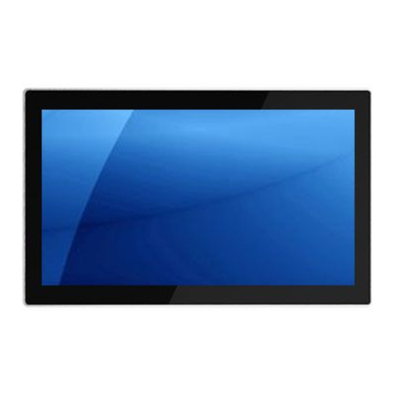
15.6" / 18.5" / 19" Wide Temp Touch Panel PC
11th Gen Intel Tiger Lake-U Core i5/i7 Processors
Wide Working Temperature Range of -40°C to 70°C
Tel: 909.597.7588
Fax: 909.597.1939
Advertisement
Table of Contents

Related Manuals for Acnodes PCW81 Series


Summary of Contents for Acnodes PCW81 Series
- Page 1 Wide Working Temperature Range of -40°C to 70°C User Manual All rights reserved. Product description and product specifications are subject to change without notice. For latest product information, please visit Acnodes’ website at www.acnodes.com. 14628 Central Ave. Chino, CA 91710 Tel: 909.597.7588 Fax: 909.597.1939...
- Page 2 Disclaimer This information in this document is subject to change without notice. In no event shall Acnodes Corporation be liable for damages of any kind, whether incidental or consequential, arising from either the use or misuse of information in this document or in any related materials.
-
Page 3: Table Of Contents
Table of Contents CHAPTER 1 GETTING STARTED 1.1 Brief Description of PCW81XX Series ................ 1.2 System Specifications ................... 1.3 Dimension ......................1.4 General Rear I/O Placement .................. 1.5 Front & Rear View of PCW81XX Series ............... 1.6 Top / Bottom I/O View ..................8 CHAPTER 2 SYSTEM SETUP 2.1 Installing of DDR4 SO-DIMM .................. -
Page 4: Chapter 1 Getting Started
Chapter 1 Getting Started 1.1 Brief Description of the PCW81XX Series The PCW81XX series is a power-optimized and delivers robust performance-per-watt for embedded HMI, powered by Intel® Gen 11 CoreTM i7/i5 UP3-Series (Tiger Lake UP3) processors. It comes with a flat-front bezel design, up to 32GB DDR4 memory, M.2 slot and a SATA 2.5-inch lockable HDD tray, audio jack, two RJ45 Ethernet, DC input, and four USB ports. -
Page 5: System Specifications
1.2 System Specifications Model PCW8156 PCW8185 PCW8190 Size 15.6 inch 18.5 inch 19 inch Max Resolution 1920 x 1080 1920 x 1080 1280 x 1024 Color 16.2M 16.7M 16.2M Luminance 450 nits 350 nits 350 nits View Angle 178/178 170/160 170/170 Contrast Ratio 1000... -
Page 6: Dimension
1.3 Dimension 1.3.1 PCW8156 Dimension 8-M4-VESA... - Page 7 1.3.2 PCW8185 Dimension 8-M4-VESA...
- Page 8 1.3.3 PCW8190 Dimension ( COVER GLASS V.A ) 8-M4-VESA...
-
Page 9: General Rear I/O Placement
1.4 General Rear I/O Placement COM 1~4 is RS-232 as default and can be adjustable to RS-422/485 by BIOS. Power input terminal block pin definition is as below. -
Page 10: Front & Rear View Of Pcw81Xx Series
1.5 Front View of the PCW81XX Series 1.5 Rear View of PCW81XX Series... -
Page 11: Top / Bottom I/O View
1.6 Top / Bottom I/O View Top View Botton View... -
Page 12: Chapter 2 System Setup
Chapter 2 System Setup 2.1 Installing of DDR4 SO-DIMM Step 1 Install DDR4 RAM module into SO-DIMM slot. Step 2 Make sure the RAM module is locked by the memory slot. -
Page 13: Installing Of
2.2 Installing of M.2 Step 1 Install M.2 into the M.2 slot. Step 2 Fasten one PH-M3x4L screw. 2.3 Installing of HDD P.10... -
Page 14: Chapter 3 Bios Setup
Chapter 3 BIOS Setup 3.1 Entering Setup BIOS provides an interface for users to check and change system configuration. The BIOS setup program is accessed by pressing the <Del> key when POST display output is shown. Figure 2-1 : Entering Setup Screen P.11... -
Page 15: Main Menu
3.2 Main Menu The main menu displays BIOS version and system information. There are two options on Main menu. Figure 2-2 : BIOS Main Menu System Date Set the Date. Use Tab to switch between Date elements. System Time Set the Time. Use Tab to switch between Time elements. P.12... -
Page 16: Advanced Function
3.3 Advanced Function Select Advanced tab to enter advanced BIOS Setup options such as CPU configuration SATA configuration, and USB configuration. Figure 2-3 : BIOS Advanced Menu P.13... - Page 17 3.3.1 CPU Configuration Figure 2-3-1 : CPU Configurations CPU Flex Ratio Override Enable/Disable CPU Flex Ratio Programming. Hardware Prefetcher To turn on/off the MLC streamer prefetcher. Adjacent Cache Line Prefetch To turn on/off prefetching of adjacent cache lines. Intel (VMX) Virtualization Technology When enabled, a VMM can utilize the additional hardware capabilities provided by Vanderpool Technology.
- Page 18 3.3.2 Power & Performance Figure 2-3-2 : Power & Performance 3.3.2.1 CPU - Power Management Control Figure 2-3-3 : CPU - Power Management Control Boot performance mode Select the performance state that the BIOS will set starting from reset vector. Intel®...
- Page 19 3.3.2.2 GT - Power Management Control Figure 2-3-2-2 : GT - Power Management Control RC6 (Render Standby) Check to enable render standby support. Maximum GT frequency Maximum GT frequency limited by the user.Choose between 300MHz (RPN) and 1150 MHz (RP0). Value beyond the range will be clipped to min/max supported by SKU. Disable Turbo GT frequency Enabled : Disables Turbo GT frequency.
- Page 20 3.3.4 Intel Time Coordinated Computing Figure 4-3-5 : Intel TCC Intel® Time Coordinated Computing options. #AC Split Lock Enable or Disable Alignment Check Exception (#AC). When enabled, this will assert an #AC when any atomic operation has an operand that crosses two cache lines. Intel(R) TCC Mode Enable or Disable Intel(R) TCC mode.
- Page 21 3.3.6 ACPI Setting Figure 4-3-1 : ACPI Settings Enable Hibernation Enables or disables system's ability to hibernate (OS/S4 Sleep State). This option may be not effective with some OS. ACPI Sleep State Select the highest ACPI sleep state the system will enter when the SUSPEND button is pressed.
- Page 22 3.3.8 IT8786 Super IO Configuration Figure 4-3-5 : Super IO Settings Serial Port 1 Configuration Set parameters of serial port 1 (COM 1). Serial Port 2 Configuration Set parameters of serial port 2 (COM 2). Serial Port 3 Configuration Set parameters of serial port 3 (COM 3). Serial Port 4 Configuration Set parameters of serial port 4 (COM 4).
- Page 23 3.3.10 Serial Port Console Redirection Figure 4-3-7 : Serial Port Console Redirection Settings Console Redirection Console redirection enable or disable. Console Redirection Settings The settings specify how the host computer and the remote computer (which the user is using) will exchange data. Both computers should have the same or compatible settings. Legacy Console Redirection Settings Legacy Console Redirection Settings Serial Port for Out-of-Band management/Windows Emergency Management...
- Page 24 3.3.11 Intel TXT information Figure 4-3-9 : Intel TXT Information Display Intel TXT information. 3.3.12 Acoustic Management Configuration Figure 4-3-11 : Acoustic Management Settings Acoustic Management Configuration Option to enable or disable Automatic Acoustic Management. 3.3.13 PCI Subsystem Settings Figure 4-3-7 : PCI Subsystem Settings BME DMA Mitigation Re-enable Bus Master Attribute disabled during Pci enumeration for PCI Bridges after SMM Locked.
- Page 25 3.3.14 USB Configuration Figure 4-3-14 : USB Settings Legacy USB Support Enables Legacy USB support. AUTO option disables legacy support if no USB devices are connected. DISABLE option will keep USB devices available only for EFI applications. XHCI Hand-off This is a workaround for OS-es without XHCI hand-off support. The XHCI ownership change should be claimed by XHCI driver.
- Page 26 3.3.15 CSM Configuration Figure 4-3-13 : CSM Settings Network Stack Enable/disable UEFI Network Stack. CSM Support Enable/disable CSM Support. GateA20 Active UPON REQUEST - GA20 can be disabled using BIOS services. ALWAYS - do not allow disabling GA20; this option is useful when any RT code is executed above 1MB.
- Page 27 3.3.16 NVME Configuration Figure 4-3-13 : NVME Settings Display NVMe Controller and drive information. 3.3.17 Network Stack Configuration Figure 4-3-12 : Network Stack Settings Network Stack Enable/disable UEFI Network Stack. Ipv4 PXE Support Enable Ipv4 PXE Boot Support. If disabled IPV4 PXE boot option will not be created. Ipv4 HTTP Support Enable/disable IPv4 HTTP boot support Ipv6 PXE Support...
-
Page 28: Chipset
3.4 Chipset Figure 4-4 : Chipset Menu System Agent (SA) Configuration System Agent (SA) Parameters. PCH-IO Configuration PCH Parameters. SW Ignition Configuration SW Ignition Configuration. Settings Delay Timer and value of Voltage limit. 3.4.1 System Agent (SA) Configuration Figure 4-4-1 : USB Settings VT-d VT-d capability. - Page 29 3.4.1.1 Memory Information of System Agent (SA) Figure 4-4-3 : Memory Information Display memory information. In-Band ECC Support Enable/Disable In-Band ECC. Either the IBECC or the TME can be enabled. P.26...
- Page 30 3.4.1.2 Graphics Configuration Figure 4-4-4 : Graphics Configuration PCH LAN Controller Enable or disable onboard NIC. Graphics Configuration Graphics turbo IMON current values supported (14-31. Skip Scanning of External Gfx Card If Enable, it will not scan for External Gfx Card on PEG and PCH PCIE ports. Primary Display Select which of IGFX/PEG/PCI graphics device should be Primary Display or select HG for Hybrid Gfx.
- Page 31 3.4.1.3 VMD Configuration Figure 4-4-5 : VMD Configuration Enable VMD controller Enable/Disable to VMD controller. Enable VMD Global Mapping Enable/ Disable to VMD Global Mapping. 3.4.1.4 SA PCI Express Configuration Figure 4-4-5 : SA PCI Express Configuration PCI Express Clock Gating PCI Express Clock Gating Enable/Disable for each root port.
- Page 32 3.4.2 PCH-IO Configuration Figure 4-4-6 : PCH-IO Configuration PCH LAN Controller Enable or disable onboard NIC. Wake on LAN Enable or disable integrated LAN to wake the system. State After G3 Specify what state to go to when power is re-applied after a power failure (G3 state). 3.4.2.1 PCI Express Configuration Figure 4-4-7 : PCI Express Configuration DMI Link ASPM Control...
- Page 33 3.4.2.2 SATA & RST Configuration Figure 4-3-10 : 2.4.2.2 SATA & RST Configurations SATA Controller(s) Enable or disable SATA Device. SATA Mode Selection Determines how SATA controller(s) operate. Software Feature Mask Configuration RAID OROM/RST driver will refer to the SWFM configuration to enable or disable the storage features.
- Page 34 3.4.2.3 BIOS Security Configuration of PCH-IO Figure 4-4-6 : BIOS Security Settings Force unlock on all GPIO pads If Enabled BIOS will force all GPIO pads to be in unlocked state. BIOS Lock Enable/disable the PCH BIOS lock enable (BLE bit) feature. 3.4.3 SW Ignition Configuration Figure 4-4-6 : SW Ignition Configuration Force unlock on all GPIO pads...
-
Page 35: Security
3.4.4 LVDS Configuration The LVDS Configuration option will be present if LVDS panel is connected on system. Figure 4-4-8 : LVDS Panel Settings LCD Panel Type Select LCD Panel Resolution. 3.5 Security Figure 4-5 : BIOS Security Menu Administrator Password Set Administrator Password. - Page 36 3.5.1 HDD Security Configuration Figure 4-5-1 : HDD Security Settings Set User Password Set HDD user password. ***Advisable to Power Cycle System after Setting Hard Disk Passwords. *** Discard or save changes option in setup does not have any impact on HDD when password is set or removed.
-
Page 37: Boot
3.6 Boot Figure 4-6 : BIOS Boot Menu Setup Prompt Timeout Number of seconds to wait for setup activation key. 65535(0xFFFF) means indefinite waiting. Bootup NumLock State Select the keyboard NumLock state. Quiet Boot Enables or disables Quiet Boot option. Boot Option #x Sets the system boot order. -
Page 38: Save & Exit
3.7 Save & Exit Figure 4-7 : Bios Save and Exit Menu Save Changes and Exit Exit system setup after saving the changes. Discard Changes and Exit Exit system setup without saving any changes. Save Changes and Reset Reset the system after saving the changes. Discard Changes and Reset Reset system setup without saving any changes.
Need help?
Do you have a question about the PCW81 Series and is the answer not in the manual?
Questions and answers