
Related Manuals for Acnodes PC 8153


Summary of Contents for Acnodes PC 8153
- Page 1 PC 8153 ® ™ 15” TFT Expandable Intel Core 2 Duo Industrial Panel PC with 2 PCI User’s Manual...
- Page 3 ’s rights, and any liability arising from such use. ACNODES does not warrant or assume any legal liability or responsibility for the accuracy, completeness or usefulness of any information in this document. ACNODES does not make any commitment to update the information in this manual.
-
Page 4: Safety Approvals
Safety Approvals CE Marking FCC Class A FCC Compliance This equipment has been tested in compliance with the limits for a Class A digital device, pursuant to Part 15 of the FCC Rules. These limits are meant to provide reasonable protection against harmful interference in a residential installation. -
Page 5: Safety Precautions
Safety Precautions Before getting started, please read the following important safety precautions. The PC 8153 Series does not come equipped with an operating system. An operating system must be loaded first before installing any software into the computer. Be sure to ground yourself to prevent static charge when installing the internal components. - Page 6 When handling boards and components, wear a wrist- grounding strap, available from most electronic component stores. Trademarks Acknowledgments ACNODES is a trademark of ACNODES Co., Ltd. IBM, PC/AT, PS/2, VGA are trademarks of International Business Machines Corporation. ® ®...
-
Page 7: Table Of Contents
Table of Contents Disclaimers ... ii Safety Approvals ... iii Safety Precautions ...iv C h a p t e r 1 Introduction ... 1 General Description... 2 System Specifications ... 3 1.2.1 Main CPU Board ... 3 1.2.2 I/O System... 3 1.2.3 System Specification ... - Page 8 System ... 59 Touch Screen ... 60 4.2.1 Specification ... 60 4.2.2 Driver Installation – Windows 2000/XP/Vista ... 61 4.2.3 Driver Installation - DOS... 64 A p p e n d i x Power Supply Specification... 67...
- Page 9 MEMO viii...
-
Page 11: General Description
This chapter contains general information and detailed specifications of the PC 8153. Chapter 1 includes the following sections: General Description System Specification Dimensions Front View & I/O Outlets Package List Introduction PC 8153 User’ s Manual C h a p t e r 1... -
Page 12: General Description
PC8153 User’ s Manual General Description ® The PC 8153 is a 15” Industrial panel PC which features Intel ™ ® Core 2 Duo processor and Intel Q965 chipset to provide powerful computing performance. This panel PC also offers the expansion ability with two PCI slots. -
Page 13: System Specifications
Standard I/O Three serial ports with power, two RS-232 and one RS- 232/422/485 One PS/2 for Keyboard and Mouse Interface Four USB Ports 2.0 compliant Two IEEE1394a Ports One DVI-I Output Introduction PC 8153 User’s Manual ® Core 2 Duo/Core Solo... -
Page 14: System Specification
PC8153 User’s Manual Ethernet First port with i82566DM Gigabit Ethernet PHY, Second port with RTL8111B for Gigabit/Fast Ethernet Audio HD Audio for two channels output MIC-In, Line-Out Storage Four SATA-300 interface Box-Header One 26-pin for shared LPT/FDD(optional) Expansion Slot Two 32-bit PCI Master slots 1.2.3 System Specification 15”... -
Page 15: Dimensions
5 to 500 Hz, 1 G random Shock (Operating) 10 G peak acceleration (11 msec. duration) NOTE All specifications and images are subject to change without notice. Dimensions This diagram shows you dimensions and outlines of the PC8153 . Introduction PC 8153 User’s Manual... -
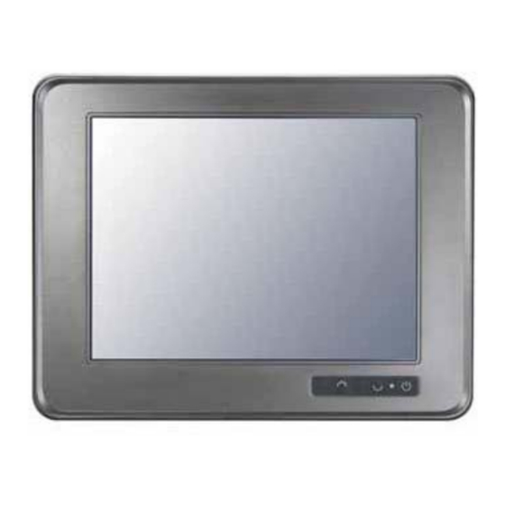
Page 17: Front View And I/O Outlets
Front View and I/O Outlets 1.4.1 Front View Please refer to the following illustration for features and controls of the PC 8153 front bezel. SEL+ SEL- Backlight ON/OFF Introduction PC 8153 User’s Manual Function... -
Page 18: I/O Outlets
PC 8153 User’s Manual 1.4.2 I/O Outlets The following figure shows the I/O locations of the PC 8153. Connector COM1 DVI-I Giga LAN x 2 IEEE 1394a x 2 USB v2.0 x 4 Mic-in, Line-Out Connector COM 2 & COM 3... -
Page 19: Package List
Package List The package bundled with your PC 8153 should contain the following items: PC 8153 x 1 AC power cord x 1 Panel mount kit x 7 Driver CDx1 LGA 775 CPU Cooler x 1 DVI TO VGA Adaptor x 1 PS/2 Splitter –... - Page 20 PC 8153 User’s Manual MEMO Introduction...
-
Page 22: Chapter 2 Hardware Installation
PC 8153 User’s Manual The PC 8153 is convenient for your various hardware configurations in flexible ways, such as CPU (Central Processing Unit), HDD (Hard Disk Drive), Memory Module (DRAM), CD-ROM, Add-On card, and more. The chapter 2 will show you how to install the hardware. - Page 23 Step 1 Unscrew screws to remove the rear chassis. Step 2 Remove the riser card fix kit. Hardware Installation PC 8153 User’s Manual...
- Page 24 PC 8153 User’s Manual Step 3 Install the CPU and DDR DRAM in the PC 8153. DRAM Hardware Installation...
-
Page 25: Installing The The Hard Disk Drive
Installing the the Hard Disk Drive The PC 8153 offers a convenient drive bay module for users to install HDD. The system offers users two 3.5” Hard Disk Drives for installation. If you want to install one or two 2.5” HDD, the PC 8153 also provides the 3.5”... - Page 26 PC 8153 User’s Manual Step 4 The installation is completed. Installing Dual 3.5” HDD If installing the dual 3.5” HDD, please follow the steps: Step 1 Change HDD bracket from 3.5” to dual 3.5”. Hardware Installation...
- Page 27 PC 8153 User’s Manual Step 2 Fix the Hard Disk to the HDD bracket to complete the installation. Hardware Installation...
- Page 28 PC 8153 User’s Manual Note When installing Dual 3.5” HDD, users must install a fan to decrease system heat. Installation step as following: Installing fan when using dual 3.5” HDD Step 1 Screw the fan to the right side of cover.
- Page 29 (1-2) (1-3) Step 2 Connect power cable of fan to 3 pin fan connector (CN3) in motherboard. Hardware Installation PC 8153 User’s Manual...
- Page 30 PC 8153 User’s Manual If installing the 2.5” HDD, please follow the steps: Step 1 Set the 2.5” HDD in the HDD bracket kit. Step 2 Install the HDD in the PC 8153. Hardware Installation...
-
Page 31: Cd-Rom Installation
CD-ROM Installation The PC 8153 offers a convenient drive bay module for users to install CD-ROM. When installing the CD-ROM, refer to the following instructions and illustration: Step 1 Unscrew screws to remove the rear chassis. Step 2 Remove the riser card fix kit. -
Page 32: Add-On Card Installation
PC 8153 User’s Manual Add-on Card Installation The PC 8153 provides a riser card for PCI slots expansion. The riser card assembly can accommodate both half-size expansion cards. To install the riser card, refer to the following figure and instructions... - Page 33 PC 8153 User’s Manual Step 4 Insert the add-on card in the socket firmly until it is completely seated. Hardware Installation...
-
Page 34: Serial Port Interface
PC 8153 User’s Manual Serial Port Interface The PC 8153 has three onboard serial ports, COM1, COM2, and COM3. COM1 is RS-232(default)/422/485 Port Connector while COM2 and COM3 are RS-232 Port Connectors. The connector, COM1, COM2, COM3 are DB-9 connector, and the following table shows the pin assignments of this connector. - Page 35 Signal TXC+ CRT-RED CRT-BLUE VGAGND NOTE It doesn’t support display in LCD and DVI-D simultaneously. DVI-D is only available after booting up in Windows XP. Hardware Installation PC 8153 User’s Manual Signal Ground TXC- CRT-GREEN CRT-HSYNC 8 C1 24 C3...
-
Page 36: Ethernet
PC 8153 User’s Manual Ethernet The PC 8153 provides a NE2000 compatible Ethernet (RJ-45) interfaces. For network connection, just plug in one cable end of the system’s 10/100/1000-Base-T Hub into a standard RJ-45 connector. Please refer to detailed pin assignment list below:... -
Page 37: Mountings Way - Panel
There is one application option for the PC 8153, Panel mounting. Panel – Mount Kit Assembley The PC 8153 is designed for panel mount application. To mount the PC 8153, the standard set of mounting kit (included in the system packaging) is needed. Hardware Installation... -
Page 38: Chapter 3 Phoenix-Award Bios Utility
PC 8153 User’s Manual C h a p t e r 3 Phoenix-Award BIOS Utility The Phoenix-Award BIOS provides users with a built-in Setup program to modify basic system configuration. All configured parameters are stored in a battery-backed-up RAM (CMOS RAM) to save the Setup information whenever the power is turned off. -
Page 39: Control Keys
Press <F1> to pop out a small Help window that provides the description of using appropriate keys and possible selections for highlighted items. Press <F1> or <Esc> to exit the Help Window. Phoenix-Award BIOS Utility PC 8153 User’s Manual BIOS default table,... -
Page 40: The Main Menu
PC 8153 User’s Manual The Main Menu Once you enter the Award BIOS CMOS Setup Utility, the Main Menu appears on the screen. In the Main Menu, there are several Setup functions and a couple of Exit options for your selection. Use arrow keys to select the Setup Page you intend to configure then press <Enter>... -
Page 41: Standard Cmos Setup Menu
It shows the current year of BIOS. year Time This item shows current time of your system with the format <hour> <minute> <second>. The time is calculated based on the 24-hour military-time clock. For example, 1 p.m. is 13:00:00. Phoenix-Award BIOS Utility PC 8153 User’s Manual... - Page 42 PC 8153 User’s Manual IDE Primary Master/Primary Slave These items identify the types of each IDE channel installed in the computer. There are 45 predefined types (Type 1 to Type 45) and 2 user’s definable types (Type User) for Enhanced IDE BIOS.
-
Page 43: Advanced Bios Features
PC 8153 User’s Manual Press <Esc> to return to the Main Menu page. Advanced BIOS Features This section allows you to configure and improve your system, to set up some system features according to your preference. Phoenix-Award BIOS Utility... - Page 44 PC 8153 User’s Manual CPU Feature Scroll to this item and press <Enter> to view the CPU Feature sub menu. Hard Disk Boot Priority Scroll to this item and press <Enter> to view the sub menu to decide the disk boot priority.
- Page 45 If set as Enabled, BIOS will shorten or skip some check items during POST. The default setting is “Enabled”. Enabled Enable Quick POST Normal POST Disabled Phoenix-Award BIOS Utility PC 8153 User’s Manual Enable cache Disable cache...
- Page 46 PC 8153 User’s Manual First/Second/Third Boot Device These items let you select the 1st, 2nd, and 3rd devices that the system will search for during its boot-up sequence. The wide range of selection includes Floppy, LS120, ZIP100, HDD0~3, SCSI, and CDROM.
- Page 47 Do not type anything, just press <Enter> and it will disable the security. Once the security is disabled, the system will boot and you can enter Setup freely. Phoenix-Award BIOS Utility PC 8153 User’s Manual 250 msec 500 msec 750 msec 1000 msec...
- Page 48 PC 8153 User’s Manual APIC Mode Use this item to enable or disable APIC (Advanced Programmable Interrupt Controller) mode that provides symmetric multi- processing (SMP) for systems. MPS Version Control For OS This item specifies the version of the Multiprocessor Specification (MPS).
-
Page 49: Advanced Chipset Features
You can reserve this area of system memory for ISA adapter ROM. When this area is reserved, it cannot be cached. The user information of peripherals that need to use this area of system memory usually discusses their memory requirements. Phoenix-Award BIOS Utility PC 8153 User’s Manual... - Page 50 PC 8153 User’s Manual PCI Express Root Port Func Scroll to this item and press <Enter> to view the sub menu to decide the PCI Express Port. Press <Esc> to return to the Advanced Chipset Featurs page. *** VGA Setting *** PEG/Onchip VGA Control Use this item to choose the primary display card.
-
Page 51: Integrated Peripherals
This item is for Intel define ADD card only. Press <Esc> to return to the Main Menu page. Integrated Peripherals This section allows you to configure your SuperIO Device, IDE Function and Onboard Device. Phoenix-Award BIOS Utility PC 8153 User’s Manual... - Page 52 PC 8153 User’s Manual On-Chip IDE Device Scroll to this item and press <Enter> to view the sub menu On-Chip IDE Device. IDE HDD Block Mode Block mode is also called block transfer, multiple commands, or multiple sector read/write. If your IDE hard drive supports...
- Page 53 ICH8 only supports AHCI under Microsoft Windows VISTA. LEGACY Mode Support Legacy mode support allows devices to function in an operating environment that is not USB-aware. Press <Esc> to return to the Integrated Peripherals page. Phoenix-Award BIOS Utility PC 8153 User’s Manual...
- Page 54 PC 8153 User’s Manual Super IO Device Scroll to this item and press <Enter> to view the sub menu Super IO Device. Onboard FDC Controller Select Enabled if your system has a floppy disk controller (FDC) installed on the system board and you wish to use it.
- Page 55 Scroll to this item and press <Enter> to view the sub menu USB Device Setting. USB (CN16) is not working when USB2.0 Controller is disabled. Press <Esc> twice to return to the Main Menu page. Phoenix-Award BIOS Utility PC 8153 User’s Manual...
-
Page 56: Power Management Setup
PC 8153 User’s Manual Power Management Setup The Power Management Setup allows you to save energy of your system effectively. It will shut down the hard disk and turn OFF video display after a period of inactivity. Phoenix-Award BIOS Utility... - Page 57 The information stored in memory will be used Phoenix-Award BIOS Utility PC 8153 User’s Manual...
- Page 58 PC 8153 User’s Manual to restore the system when a “wake up” event occurs. Run VGABIOS if S3 Resume When this item is set Auto, the system will run VGA BIOS if it is reaumed from the S3 state. Power Management This option allows you to select the type (or degree) of power saving for Doze, Standby, and Suspend modes.
- Page 59 The default value is “Enabled”. Resume by Alarm If enable this item, the system can automatically resume after a fixed time in accordance with the system’s RTC (real time clock). Phoenix-Award BIOS Utility PC 8153 User’s Manual...
- Page 60 PC 8153 User’s Manual ** Reload Global Timer Events ** Global Timer (power management) events can prevent the system from entering a power saving mode or can awaken the system from such a mode. Primary/Secondary IDE 0/1 Use this item to configure the IDE devices monitored by the system.
-
Page 61: Pnp/Pci Configuration Setup
Plug and Play-compatible devices. If you select Auto, all interrupt request (IRQ), DMA assignment, and Used DMA fields disappear, as the BIOS automatically assigns them. The default value is “Manual”. IRQ Resources When resources are controlled manually, assign each system Phoenix-Award BIOS Utility PC 8153 User’s Manual... - Page 62 PC 8153 User’s Manual interrupt to one of the following types in accordance with the type of devices using the interrupt: 1. Legacy ISA Devices compliant with the original PC AT bus specification, requiring a specific interrupt (such as IRQ4 for serial port PCI/ISA PnP Devices compliant with the Plug and Play standard, whether designed for PCI or ISA bus architecture.
-
Page 63: Pc Health Status
These read-only fields show the functions of the hardware thermal sensor by CPU thermal diode that monitors the chip blocks to ensure a stable system. Vcore +3.3V/+5V/+12V/VBAT(V)/5VSB Show you the voltage of +3.3V/+5V/+12V. Press <Esc> to return to the Main Menu page. Phoenix-Award BIOS Utility PC 8153 User’s Manual... -
Page 64: Frequency/Voltage Control
PC 8153 User’s Manual 3.12 Frequency/Voltage Control This section is to control the CPU frequency and Supply Voltage, DIMM OverVoltage and AGP voltage. CPU Clock Ratio Use this item to select the CPU’s frequency. Auto Detect PCI Clk The enabled item can automatically disable the clock source for a PCI slot without a module, to reduce EMI (Electro Magnetic Interference). -
Page 65: Load Optimized Defaults
PC 8153 User’s Manual 3.13 Load Optimized Defaults This option allows you to load the default values to your system configuration. These default settings are optimal and enable all high performance features. To load SETUP defaults value to CMOS SRAM, enter “Y”. If not, enter “N”. -
Page 66: Set Supervisor/User Password
PC 8153 User’s Manual 3.14 Set Supervisor/User Password You can set either supervisor or user password, or both of then. The differences between are: Supervisor password: can enter and change the options of the setup menus. User password: just can enter but do not have the right to change the options of the setup menus. -
Page 67: Save & Exit Setup
PC 8153 User’s Manual 3.15 Save & Exit Setup This allows you to determine whether or not to accept the modifications. Typing “Y” quits the setup utility and saves all changes into the CMOS memory. Typing “N” brigs you back to Setup utility. -
Page 68: Exit Without Saving
PC 8153 User’s Manual 3.16 Exit Without Saving Select this option to exit the Setup utility without saving the changes you have made in this session. Typing “Y” will quit the Setup utility without saving the modifications. Typing “N” will return you to Setup utility. - Page 69 PC 8153 User’s Manual MEMO Phoenix-Award BIOS Utility...
-
Page 70: Chapter 4 Driver Installation
C h a p t e r 4 Driver Installation System PC 8153 supports Windows 2000/XP/Vista. To facilitate the installation of the system driver, please carefully read the instructions in this chapter before start installing. 1. Here is the path for the system driver: Panel series\PC 8153\Driver 2. -
Page 71: Touch Screen
12V: 23mA+ i where (i = v/touch screen sheet 5V 20mA+ i where (i = v/touch screen sheet Mechanical Size 60(L) x 26(W) x 8.3(H)mm Portrait Support 90o to 270o screen rotation Others Touch activate indication LED on board Driver Installation PC 8153 User’s Manual... -
Page 72: Driver Installation - Windows 2000/Xp/Vista
PC 8153 User’s Manual 4.2.2 Driver Installation – Windows 2000/XP/Vista The PC 8153 provides a driver of the touch screen that users can install it under operating system Windows 2000/XP/Vista. To facilitate this touch screen driver installation, users should read the instructions in this chapter carefully before start the installation. - Page 73 PC 8153 User’s Manual Select the “Standard Calibrate” tab. Driver Installation...
- Page 74 PC 8153 User’s Manual Calibration: To adjust the display with touch panel, click “Calibration” and follow the calibrate point to do calibration; there are five points on screen for calibration. Press OK. Driver Installation...
-
Page 75: Driver Installation - Dos
IRQ number. For example, you do not need to detect IRQ5, and the command is: C:\PEN MOUNT\PMDETECT -N5 4. If you do not need to detect IRQ5 and IRQ9, the command is: Driver Installation PC 8153 User’s Manual Suggest choose “YES”... - Page 76 PC 8153 User’s Manual C:\PEN MOUNT\PMDETECT -N5 -N9 Do Calibration 1. To adjust the touch screen mapping properly to display screen, use PM.BAT (C:\PEN MOUNT\PM) to do calibration. Choose “1” DO CALIBRATION (adjust screen mapping). 2. The message pops out to ask if you select the video mode number.
- Page 77 PC 8153 User’s Manual MEMO Driver Installation...
-
Page 78: Appendix Power Supply Specification
PC 8153 User’s Manual Power Supply Specification Power Supply FSP250-50GUB (250W, AC100~240V Input) Electrical Requirements OUTPUT ELECTRICAL REQUIREMENTS The subject power supply will meet all electrical specifications below, over the full operation temperature range and dynamic load regulation. OUTPUT RATING... - Page 79 230V / 50Hz : 17 m-sec. Minimum. OUTPUT RISE TIME (10% TO 95% OF FINAL OUTPUT VALUE, @FULL LOAD) 115V-rms or 230V-rms OVER VOLTAGE PROTECTION Voltage Source +3.3V +12V Power Supply Specification PC 8153 User’s Manual +12V -12V +5VSB 0.1A 0.8A 0.1A 0.1A 0.1A 0.1A...
-
Page 80: Environmental Requirements
PC 8153 User’s Manual SHORT CIRCUIT PROTECTION Output short circuit is defined to be a short circuit load of less than 0.1 ohm. In the event of an output short circuit condition on +3.3V, +5V or +12V output, the power supply will shutdown and latch off. The power supply... - Page 81 HDBK; latest revision, are exceed 100,000 hours with all output at maximum load and an ambient temperature of 25 ℃. Safety NEMKO EN 60950 TUV EN60950 OR VDE EN60950 UL 60950 CSA 22.2 NO. 60950 IEC 60950 Power Supply Specification PC 8153 User’s Manual...
Need help?
Do you have a question about the PC 8153 and is the answer not in the manual?
Questions and answers