Table of Contents
Advertisement
Quick Links
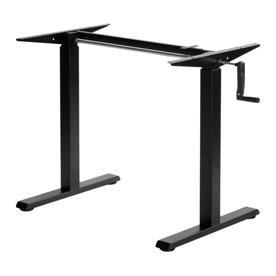
Black Compact Crank Height Adjustable Desk Frame
Instruction Manual
SKU: DESK-M051CB
Scan the QR code with your mobile device or follow the link
for helpful videos and specifications related to this product.
https://vivo-us.com/products/desk-m051cb
GET IN TOUCH | Monday-Friday from 7:00am-7:00pm CST
help@vivo-us.com
www.vivo-us.com
Chat live with an agent!
309-278-5303
Advertisement
Table of Contents

Related Manuals for Vivo DESK-M051CB


Summary of Contents for Vivo DESK-M051CB
- Page 1 Black Compact Crank Height Adjustable Desk Frame Instruction Manual SKU: DESK-M051CB Scan the QR code with your mobile device or follow the link for helpful videos and specifications related to this product. https://vivo-us.com/products/desk-m051cb GET IN TOUCH | Monday-Friday from 7:00am-7:00pm CST help@vivo-us.com...
- Page 2 WARNING! If you do not understand these directions, or if you have any doubts about the safety of the installation, please call a qualified technician. Check carefully to make sure there are no missing or defective parts. Improper installation may cause damage or serious injury. Do not use this product for any purpose that is not explicitly specified in this manual and do not exceed weight capacity.
- Page 3 ASSEMBLY STEPS STEP 1 Loosen the screws on Telescopic Crossbar (A) using 4mm Allen Wrench (T-A) and extend the sides. STEP 2 Attach Telescopic Crossbar (A) to Leg (B) and Leg with Gearbox (C) using M6x25 mm Screws (S-A). Tighten with 4mm Allen Wrench (T-A).
- Page 4 STEP 3 Assemble Side Brackets (D) to the frame assembly using M6x10mm Screws (S-B) and 5mm Allen Wrench (T-B). STEP 4 Mount Feet (E) to Leg (B) and Leg with Gearbox (C) using M6x35mm Screws (S-C) and 4mm Allen Wrench (T-A).
- Page 5 STEP 5 Extend Telescopic Crossbar (A) to fit the desktop. Be sure to leave 4”-5” (100mm-130mm) of space from the edge of the desktop on either side of the frame. Retighten the screws on Telscopic Crossbar (A) using 4mm Allen Wrench (T-A). STEP 6 Secure the frame assembly to the desktop using ST4.2x16mm Screws (S-E) and a Phillips screwdriver.
- Page 6 STEP 7 Loosen the knob on Sync Rod (F) and insert the rod into Leg (B). Extend Sync Rod (F) onto Leg With Gearbox (C). Tighten both knobs on Sync Rod (F) using Wrench (T-C). STEP 8 Insert Crank Handle (G) into Crank Handle Collar (H). Secure Crank Handle Collar (H) using M4x8mm Screw (S-E) and a Phillips screwdriver.
- Page 7 STEP 9 Turn Crank Handle (G) clockwise to raise the desk, and counter clockwise to lower. Slide Crandle Handle (G) in and flip the handle around to store it when not in use. CAUTION! Do not exceed desk Keep area of vertical motion Keep weight on desk Leave enough slack weight limit.
- Page 8 AVG. RESPONSE TIME (within office hrs) - 23% within < 15m - 38% within < 30m - 61% within < 1hr - 83% within < 2hr - 92% within < 3hr FOR MORE VIVO PRODUCTS, CHECK OUT OUR WEBSITE AT: www.vivo-us.com...
Need help?
Do you have a question about the DESK-M051CB and is the answer not in the manual?
Questions and answers