Table of Contents
Advertisement
Available languages
Available languages
Quick Links
IMPORTANT! Read all instructions before installing and using. Installer: This manual must be delivered to the end user.
WARNING!
Failure to install or use this product according to manufacturer's recommendations may result in property damage, serious injury, and/
or death to those you are seeking to protect!
Do not install and/or operate this safety product unless you have read and understood the safety information
contained in this manual.
1.
Proper installation combined with operator training in the use, care, and maintenance of emergency warning devices are essential to
ensure the safety of emergency personnel and the public.
2.
Emergency warning devices often require high electrical voltages and/or currents. Exercise caution when working with live electrical
connections.
3.
This product must be properly grounded. Inadequate grounding and/or shorting of electrical connections can cause high current arcing,
which can cause personal injury and/or severe vehicle damage, including fire.
4.
Proper placement and installation is vital to the performance of this warning device. Install this product so that output performance of
the system is maximized and the controls are placed within convenient reach of the operator so that they can operate the system without
losing eye contact with the roadway.
5.
Do not install this product or route any wires in the deployment area of an air bag. Equipment mounted or located in an air bag
deployment area may reduce the effectiveness of the air bag or become a projectile that could cause serious personal injury or death.
Refer to the vehicle owner's manual for the air bag deployment area. It is the responsibility of the user/operator to determine a suitable
mounting location ensuring the safety of all passengers inside the vehicle particularly avoiding areas of potential head impact.
6.
It is the responsibility of the vehicle operator to ensure daily that all features of this product work correctly. In use, the vehicle operator
should ensure the projection of the warning signal is not blocked by vehicle components (i.e., open trunks or compartment doors),
people, vehicles or other obstructions.
7.
The use of this or any other warning device does not ensure all drivers can or will observe or react to an emergency warning signal.
Never take the right-of-way for granted. It is the vehicle operator's responsibility to be sure they can proceed safely before entering an
intersection, drive against traffic, respond at a high rate of speed, or walk on or around traffic lanes.
8.
This equipment is intended for use by authorized personnel only. The user is responsible for understanding and obeying all laws
regarding emergency warning devices. Therefore, the user should check all applicable city, state, and federal laws and regulations. The
manufacturer assumes no liability for any loss resulting from the use of this warning device.
Notes:
1.
Larger wires and tight connections will provide longer service life for components. For high current wires it is highly recommended
that terminal blocks or soldered connections be used with shrink tubing to protect the connections. Do not use insulation displacement
connectors (e.g., 3M Scotchlock type connectors).
2.
Route wiring using grommets and sealant when passing through compartment walls. Minimize the number of splices to reduce voltage
drop. All wiring should conform to the minimum wire size and other recommendations of the manufacturer and be protected from moving
parts and hot surfaces. Looms, grommets, cable ties, and similar installation hardware should be used to anchor and protect all wiring.
Fuses or circuit breakers should be located as close to the power takeoff points as possible and properly sized to protect the wiring and
3.
devices.
4.
Particular attention should be paid to the location and method of making electrical connections and splices to protect these points from
corrosion and loss of conductivity.
5.
Ground termination should only be made to substantial chassis components, preferably directly to the vehicle battery.
6.
Circuit breakers are very sensitive to high temperatures and will "false trip" when mounted in hot environments or operated close to their
capacity.
Specifications
Input Voltage: 12-24 VDC
Current:
Switch 1 (White): 0.38A @ 12 VDC Nominal
Switch 2 (Blue): 1.08A @ 12 VDC Nominal
Power:
Switch 1 (White): 4.89W @ 12 VDC Nominal
Switch 2 (Blue): 13.77W @ 12 VDC Nominal
Wiring:
2-20 AWG wires - Red (Positive +), Black (Ground -)
Fuse:
2A slow blow fuse (user supplied)
3-position switch - Switch 1 (White), Off, Switch 2 (Blue)
Switch:
Installation and Operation Instructions
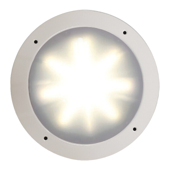
Antimicrobial Dome Light
with
™
Page 1 of 4
Advertisement
Table of Contents

Subscribe to Our Youtube Channel
Related Manuals for Code 3 PCL-LED-VV


Summary of Contents for Code 3 PCL-LED-VV
- Page 1 Installation and Operation Instructions Antimicrobial Dome Light with ™ IMPORTANT! Read all instructions before installing and using. Installer: This manual must be delivered to the end user. WARNING! Failure to install or use this product according to manufacturer’s recommendations may result in property damage, serious injury, and/ or death to those you are seeking to protect! Do not install and/or operate this safety product unless you have read and understood the safety information contained in this manual.
-
Page 2: Specifications
Specifications Input Voltage: 12-24 VDC Current: Switch 1 (White): 0.38A @ 12 VDC Nominal Switch 2 (Blue): 1.08A @ 12 VDC Nominal Power: Switch 1 (White): 4.89W @ 12 VDC Nominal Switch 2 (Blue): 13.77W @ 12 VDC Nominal Wiring: 2-20 AWG wires - Red (Positive +), Black (Ground -) Fuse: 2A slow blow fuse (user supplied) - Page 3 Notes Page 3 of 4...
-
Page 4: Warranty
*Code 3®, Inc. reserves the right to repair or replace at its discretion. Code 3®, Inc. assumes no responsibility or liability for expenses incurred for the removal and /or reinstallation of products requiring service and/or repair.;... - Page 5 Instrucciones de instalación y operación Luz de techo antimicrobiana ™ ¡IMPORTANTE! Lea todas las instrucciones antes de instalar y utilizar. Instalador: Este manual se debe entregar al usuario final. ¡ADVERTENCIA! Si no sigue las instrucciones del fabricante a la hora de instalar o usar el producto, pueden producirse daños materiales, y lesiones graves o incluso mortales a aquellos que pretende proteger! No instale ni opere este producto de seguridad, a menos que haya leído y comprendido la información de seguridad contenida en este manual.
-
Page 6: Especificaciones
Especificaciones Voltaje de entrada: 12-24 VDC Corriente: Interruptor 1 (Blanco): 0,38 A a 12 V CC nominal Interruptor 2 (Azul): 1,08 A a 12 V CC nominal Alimentación: Interruptor 1 (Blanco): 4,89 W a 12 V CC nominal Interruptor 2 (Azul): 13,77 W a 12 V CC nominal Cableado: 2 cables de 20 AWG: Rojo (positivo +), Negro (tierra -) Fusible:... - Page 7 * Code 3®, Inc. se reserva el derecho a realizar reparaciones o reemplazar productos según su criterio. Code 3®, Inc. no asume responsabilidad alguna por los gastos efectuados para la extracción o la reinstalación de los productos que requieren servicios o reparaciones, por el embalaje, la manipulación y el envío ni por la manipulación de los productos devueltos al remitente después de que se haya prestado el servicio.
-
Page 8: Instructions D'installation Et D'utilisation
Instructions d’installation et d’utilisation Plafonnier antimicrobien avec ™ IMPORTANT! Lisez toutes les instructions avant d’installer et d’utiliser le produit. Installateur : ce manuel doit être remis à l’utilisateur final. AVERTISSEMENT! Le non-respect des recommandations du fabricant au cours de l’installation ou de l’utilisation de ce produit peut entraîner des dommages matériels et causer à... -
Page 9: Caractéristiques
Caractéristiques Tension d’entrée: 12-24 VDC Courant : Commutateur 1 (blanc) : 0,38 A à 12 V c.c. nominal Commutateur 2 (bleu) : 1,08 A à 12 V c.c. nominal Alimentation : Commutateur 1 (blanc) : 4,89 W à 12 V c.c. nominal Commutateur 2 (bleu) : 13,77 W à... -
Page 10: Garantie
*Code 3 , Inc. se réserve le droit de réparer ou de remplacer le produit à sa discrétion. Code 3 , Inc. n’assume aucune responsabilité pour les dépenses engagées pour le retrait ou la réinstallation des produits nécessitant une réparation ou un entretien; ni pour l’emballage, la manutention et l’expédition; ni pour la manutention des produits retournés à l’expéditeur après la prestation. -
Page 11: Installations- Und Bedienungsanleitung
Installations- und Bedienungsanleitung Antimikrobielle Deckenleuchte mit ™ WICHTIG! Lesen Sie vor der Installation und Verwendung alle Anweisungen. Monteur: Diese Anleitung muss dem Endbenutzer zugestellt werden. WARNUNG! Wenn Sie dieses Produkt nicht gemäß den Empfehlungen des Herstellers installieren oder verwenden, kann dies zu Sachschäden, schweren Personenschäden und/oder zum Tod für Sie und die Personen, denen Sie helfen möchten, führen! Installieren und/oder verwenden Sie dieses Sicherheitsprodukt nur, wenn Sie die Sicherheitsinformationen in dieser Anleitung gelesen und verstanden haben. -
Page 12: Spezifikationen
Spezifikationen Eingangsspannung: 12-24 VDC Strom: Schalter 1 (weiß): 0,38 A bei 12 V DC Nennspannung Schalter 2 (blau): 1,08 A bei 12 V DC Nennspannung Leistung: Schalter 1 (weiß): 4,89 W bei 12 V DC Nennspannung Schalter 2 (blau): 13,77 W bei 12 V DC Nennspannung Verkabelung: 2-20 AWG-Kabel –... - Page 13 Produkt zu vermeiden. *Code 3®, Inc. behält sich das Recht vor, Reparaturen und Ersatzlieferungen nach eigenem Ermessen vorzunehmen. Code 3®, Inc. übernimmt keine Verantwortung oder Haftung für Ausgaben, die für die Demontage bzw. Neuinstallation von Produkten anfallen, die gewartet bzw. repariert werden müssen oder für die Verpackung, die Handhabung und den Versand. Dies gilt ebenfalls für die Handhabung von Produkten, die nach Erbringung der Dienstleistung an den Absender zurückgeschickt wurden.
Need help?
Do you have a question about the PCL-LED-VV and is the answer not in the manual?
Questions and answers