Table of Contents
Advertisement
INSTALLATION
& OPERATION
MANUAL
61 35 0 440 635
BMW R1200RT-P
SIREN/FLASHER
R 1200RT-P BMW SIREN/FLASHER
IMPORTANT:
Contents:
Installation and Mounting ..................................... 2
Siren Standard Features ..................................... 2
Siren Set-Up and Adjustment .............................. 4
Siren Operation ................................................... 4
Siren Troubleshooting Guide ............................... 5
Flasher Troubleshooting Guide............................ 6
Flasher Set-Up .................................................... 8
Siren/Flasher Input/Output Table .......................... 9
Warranty ........................................................... 10
Read all instructions and warnings before installing and using.
INSTALLER:
This manual must be delivered to the end user of this equipment.
Advertisement
Table of Contents
Troubleshooting

Related Manuals for Code 3 R 1200RT-P


Summary of Contents for Code 3 R 1200RT-P
-
Page 1: Table Of Contents
INSTALLATION & OPERATION MANUAL 61 35 0 440 635 BMW R1200RT-P SIREN/FLASHER R 1200RT-P BMW SIREN/FLASHER Contents: Installation and Mounting ........2 Siren Standard Features ........2 Siren Set-Up and Adjustment ......4 Siren Operation ........... 4 Siren Troubleshooting Guide ....... 5 Flasher Troubleshooting Guide...... -
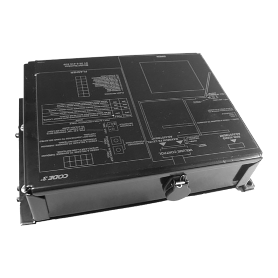
Page 2: Installation And Mounting
Installation & Mounting of Siren/Flasher Unit The siren/flasher is designed to be mounted under the radio box/seat area (see below). There is no provision for an alternate mounting location in this configuration. Remove the radio box and the seat. The siren will mount under the seat bracket. - Page 3 Wail - A continuous positive signal applied to this input from a user supplied switch will cause the siren to activate in wail mode for as long as the switch remains in the on position. Airhorn - A continuous positive signal applied to this input from a user supplied switch will cause the siren to generate the Airhorn signal for as long as the switch remains in the on position.
-
Page 4: Siren Set-Up And Adjustment
Siren Set-Up and Adjustment The only adjustments necessary for the siren are Maximum P.A. Adjustment (accessible from the outside of the unit), and Maximum RRB Adjustment (accessible only with the cover removed). Audio Adjustments Maximum Radio Rebroadcast (RRB) Adjustment - This trimmer (under the siren cover) sets the maximum level that the 2-way radio will reach with the front panel VOLUME control in the fully clockwise position. -
Page 5: Siren Troubleshooting Guide
SIREN TROUBLESHOOTING GUIDE PROBLEM PROBABLE CAUSE REMEDY NO SIREN OUTPUT. A. SHORTED SPEAKER OR SPEAKER A. CHECK W IRES. SIREN IN OVER CURRENT CONNECTIONS. PROTECTION MODE. 10A FUSE BLOW S. A. AMPLIFIER POW ER W IRES REVERSED A. CHECK POLARITY. POLARITY. -
Page 6: Flasher Troubleshooting Guide
FLASHER TROUBLESHOOTING GUIDE PROBLEM PROBABLE CAUSE REMEDY SIDE FACING LIGHT NOT A. DIP SW ITCH IN THE W RONG POSITION A. CHECK DIP W ORKING W ITH FRONT OR NOT FULLY IN POSITION. SW ITCHES. OR REAR GROUP AS EXPECTED. LIGHTHEAD DOES NOT A. - Page 7 CONNECTION OF A 58 WATT SPEAKER TO THE SPKR TERMINAL WILL CAUSE THE SPEAKER TO BURN OUT, AND WILL VOID THE SPEAKER WARRANTY! The sound projecting opening should be pointed forward, parallel to the ground, and not WARNING! obstructed or muffled by structural components of the vehicle. Concealed or under-hood W A R N I N G ! mounting in some cases will result in a dramatic reduction in performance.
-
Page 8: Flasher Set-Up
Flasher Set-Up Changing flash patterns for the STD ( SW2) or Interclear mode ( SW3) The flash pattern can be changed (while the LED lightheads are on) by pressing the designated switch on the PCB and releasing. Patterns - (all patterns are alternating): 1. -
Page 9: Siren/Flasher Input/Output Table
VOLUME CONTROL SHORTING HEADER INPUT RRB AUDIO HEADER NORMAL ADJUSTMENT CHP RADIO MAXIMUM PA LEVEL MOMENTARY COMPATIBLE PUSHBUTTONS ADJUSTMENT POS. 3 IN "ON" POSITION SETS LEFT FRONT LIGHT TO STEADY BURN 2 POSITION DIPSWITCH POS 1 - (NOT USED) POS 2 - NOHYPERYELP WHEN ON OUTPUT HEADER... -
Page 10: Warranty
10986 N. Warson Road St. Louis, Missouri 63114-2029—USA Revision 0, 11/10 - Instruction Book Part No. T16474 Code 3 is a registered trademark of Code 3, Inc a subsidiary of Public Safety Equipment, Inc. ©2010 Code 3, Inc. Printed in USA...
Need help?
Do you have a question about the R 1200RT-P and is the answer not in the manual?
Questions and answers