Table of Contents
Advertisement
Quick Links
IMPORTANT! Read all instructions before installing and using. Installer: This manual must be delivered to the end user.
WARNING!
Failure to install or use this product according to manufacturer's recommendations may result in property damage, serious bodily/
personal injury, and/or death to you and those you are seeking to protect!
Do not install and/or operate this safety product unless you have read and understand the safety
information contained in this manual.
1. Proper installation combined with operator training in the use, care and maintenance of emergency warning devices are essential to
ensure the safety of emergency personnel and the public.
2. Emergency warning devices often require high electrical voltages and/or currents. Exercise caution when working with live electrical
connections.
3. This product must be properly grounded. Inadequate grounding and/or shorting of electrical connections can cause high current
arcing, which can cause personal injury and/or severe vehicle damage, including fire.
4. Proper placement and installation is vital to the performance of this warning device. Install this product so that output performance of
the system is maximized and the controls are placed within convenient reach of the operator so that s/he can operate the system
without losing eye contact with the roadway.
5. It is the responsibility of the vehicle operator to ensure daily that all features of this product work correctly. In use, the vehicle operator
should ensure the projection of the warning signal is not blocked by vehicle components (i.e., open trunks or compartment doors),
people, vehicles or other obstructions.
6. The use of this or any other warning device does not ensure all drivers can or will observe or react to an emergency warning signal.
Never take the right-of-way for granted. It is your responsibility to be sure you can proceed safely before entering an intersection, drive
against traffic, respond at a high rate of speed, or walk on or around traffic lanes.
7. This equipment is intended for use by authorized personnel only. The user is responsible for understanding and obeying all laws
regarding emergency warning devices. Therefore, the user should check all applicable city, state, and federal laws and regulations.
The manufacturer assumes no liability for any loss resulting from the use of this warning device.
8. This product may contain high intensity LEDs staring directly into these lights could result in temporary and/or permanent vision
impairment.
Specifications:
Cross Section:
Max Input Voltage:
Nominal Input Voltage:
Fusing Requirement:
Matrix Connectivity:
Temp. Range:
Additional Matrix Resources
Product Information:
www.code3esg.com/us/en/products/matrix
Training Videos:
www.youtube.com/c/Code3Inc
Matrix Software:
http://software.code3esg.global/updater/matrix/downloads/Matrix.exe
Covert Series
1.6" x 12.3"
21 Series
2.1" x 12.3"
27 Series
2.7" x 12.3"
10-16 VDC
12 VDC
30A / 60A
Covert Series
CAT5
21 / 27 Series
CAT5
-40ºC to 65ºC
(-40ºF to 149ºF)
Installation and Operation Instructions
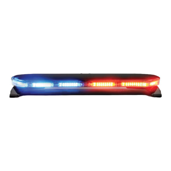
MATRIX-ENABLED
21/27/COVERT SERIES LIGHTBARS
Light Module Current (@ 12 VDC):
27 Series
27 Series
27 Series
27 Series
27 Series
21 Series
21 Series
21 Series
Covert / 21 Series
21 Series
21 Series
Covert / 21 Series
Covert / 21 Series
Covert / 21 Series
Covert / 21 Series
Prizm
Single Color
5 LED AL, WL, RD
Prizm
Single Color
8 LED Directional
Prizm
Single Color
12 LED Directional
Prizm
Dual Color
24 LED Directional
Prizm
Tri Color
24 LED Directional
Torus
Single Color
3 LED AL, WL, TD
Torus
Single Color
3 LED Directional
Torus
Single Color
4 LED Directional
Torus
Dual Color
6 LED AL, WL, TD
Torus
Single Color
6 LED Directional
Torus
Single Color
8 LED Directional
Torus
Tri Color
9 LED AL, WL, TD
Torus
Dual Color
12 LED Directional
Torus
Dual Color
16 LED Directional
Torus
Tri Color
18 LED Directional
0.7 A
1.3 A
1.7 A
2.0 A
1.1 A
0.4 A
0.6 A
0.8 A
0.6 A
1.1 A
1.3 A
0.6 A
1.2 A
1.3 A
1.2 A
Page 1 of 16
Advertisement
Table of Contents

Subscribe to Our Youtube Channel
Related Manuals for Code 3 21 COVERT Series


Summary of Contents for Code 3 21 COVERT Series
- Page 1 Installation and Operation Instructions MATRIX-ENABLED 21/27/COVERT SERIES LIGHTBARS IMPORTANT! Read all instructions before installing and using. Installer: This manual must be delivered to the end user. WARNING! Failure to install or use this product according to manufacturer’s recommendations may result in property damage, serious bodily/ personal injury, and/or death to you and those you are seeking to protect! Do not install and/or operate this safety product unless you have read and understand the safety information contained in this manual.
-
Page 2: Installation And Mounting
Carefully remove the product and place it on a flat surface. Examine the unit for transit damage and locate all parts. If damage is found or parts are missing, contact the transit company or Code 3. Do not use damaged or broken parts. - Page 3 Direct Mount Option: 1. Remove the mounting feet from the lightbar. 2. Insert the four (4) 5/16”-18 carriage bolts in the channels on the under side of the lightbar. 3. Place the lightbar over the center of the vehicle and slide the mounting hardware into position near the curved edge when possible as shown in FIGURE 2.
- Page 4 Pylon/Headache Rack Option: 1. Remove the mounting feet from the lightbar. 2. Insert the four (4) 5/16”-18 carriage bolts in the channels on the under side of the lightbar and loosely attach the mounting brackets. 3. Place the lightbar on the vehicle and slide the mounting brackets into position. 4.
- Page 5 See the Wiring section of this manual for further wiring instructions. Figure 4 *For a full list of vehicle specific brackets, please reference a Code 3 catalog or contact a Code 3 representative. Page 5 of 16...
-
Page 6: Wiring Instructions
Wiring Instructions: IMPORTANT! This unit is a safety device and it must be connected to its own separate, fused power point to assure its continued operation should any other electrical accessory fail. Do not wire in parallel with any other accessory. Notes: •... - Page 7 The Matrix network is designed to conveniently accommodate a large number of accessory devices. As more products utilizing CAT5 connectivity are integrated into the vehicle, routing of the cables can be accomplished in ‘daisy chain’ fashion, if desired. Serial lightbars utilizing CAT5 will always be the last device in either the PRI-1 or SEC-2 chain.
- Page 8 21 & 27 Series Lightbar Flash Pattern Chart SAE J845 (180°)* SAE J595 CA TITLE 13 Description A, B, R A, B, R A, B, R Sweep Dual End Rotate Pursuit Pursuit (Steady Front Primary) Cruise Low Cruise Low Full Bar Cruise High Flicker Cruise Low Flicker Cruise High...
- Page 9 Covert Bar Flash Pattern Chart SAE J845 (180°)* SAE J595 CA TITLE 13 Description A, B, R A, B, R A, B, R Sweep Dual End Rotate Pursuit Pursuit (Steady Front Primary) Cruise Low Cruise Low Full Bar Cruise High Flicker Cruise Low Flicker Cruise High Takedown/Alley Flash...
- Page 10 Replacement Parts and Assemblies: There are many different types of light-heads producing various warning signals in the lightbar as explained below. All 21/27 Series Lightbar retaining screws need to be torqued to 40 +0/-5 IN-LBS (4.52 +0/- 0.56 Nm). Covert Series Lightbar retaining screws need to be torqued to 10 +/- 1 IN-LBS (1.13 +/- 0.11 N-M) Note: LED modules are not user serviceable.
- Page 11 Description Part No. Modules Serial Interface Box (SIB) CZMATSIB Boards Lightbar Master Controller Board CZMATLBC Lightbar Power HUB Board CZMATPH Lenses 21 Series, Lower Outboard Lens, Clear CZ2101C 21 Series, Lower Outboard Lens, Tint CZ2101T 21 Series, Lower Center 11" Lens, Clear CZ2111C 21 Series, Lower Center 11"...
- Page 12 Description Part No. Lenses (continued) 27 Series, Upper Center 8" Lens, Blue CZ2708UB 27 Series, Upper Center 8" Lens, Amber CZ2708UA 27 Series, Upper Center 8" Lens, Black CZ2708UBLK 21/27 Series, Lower Center 18" Lens, Tint CR1618LSMK 21/27 Series, Lower Center 18" Lens, Clear CR1618LCLE 21/27 Series, Upper Center 18"...
- Page 13 Description Part No. Lenses (continued) Covert, Upper 22.5" Lens, Black CR1623UBLA Covert, Upper 22.5" Lens, Blue CR1623UBLU Covert, Upper Center 18" Lens, Tint, Photocell CR1618PHOTOSMK Covert, Upper Center 18" Lens, Amber, Photocell CR1618PHOTOAMB Covert, Upper Center 18" Lens, Red, Photocell CR1618PHOTORED Covert, Upper Center 18"...
- Page 14 Description Part No. Lightheads (continued) Covert / 21 Series, Torus, 12LED, Red/Blue, (Dual Color) CZ2112RB Covert / 21 Series, Torus, 12LED, Green/White, (Dual Color) CZ2112GW Covert / 21 Series, Torus, 12LED, Red/White, (Dual Color) CZ2112RW Covert / 21 Series, Torus, 16LED, Amber/White, (Dual Color) CZ2116AW Covert / 21 Series, Torus, 16LED, Blue/Amber, (Dual Color) CZ2116BA...
-
Page 15: Maintenance
Maintenance: Occasional cleaning of the lenses will ensure optimum light output. Take care when cleaning lenses. Although very impact resistant, polycarbonate scratches easily. Clean the lens and base with soap and water or a lens polish using a microfiber or other lint free soft cloth. Do not use solvents as they may damage the polycarbonate. -
Page 16: Product Returns
*Code 3®, Inc. reserves the right to repair or replace at its discretion. Code 3®, Inc. assumes no responsibility or liability for expenses incurred for the removal and /or reinstallation of products requiring service and/or repair.;...
Need help?
Do you have a question about the 21 COVERT Series and is the answer not in the manual?
Questions and answers