Advertisement
Table of Contents
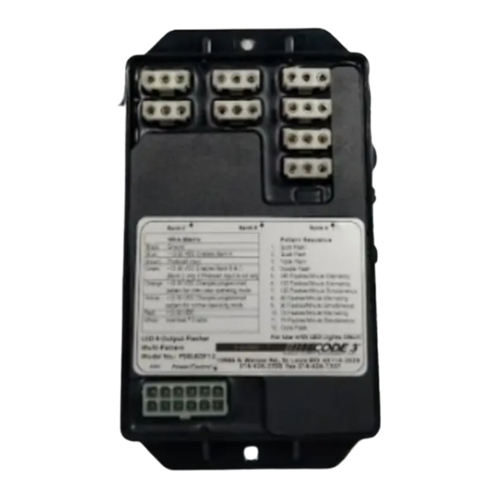
8 OUTPUT LED FLASHER MULTI-PATTERN
ELECTRICAL SPECIFICATION
Input Voltage Range
Output Drive Current
Operating Temperature
Flash Patterns
Output Drive Method
Pattern Control Method
Standby Current
Reverse Polarity Protection
Short Circuit Protection
Thermal Protection
MECHANICAL SPECIFICATIONS
Weather resistance
Potted to protect circuitry, but not
waterproof
Dimensions
6.0" x 3.6" x .75"
WARNING
This device is intended for use with LED Lights ONLY!! Use of this
product on an Incandescent, Halogen or any light source other than
LED's may damage the unit and void the warranty.
The use of this or any warning device does not insure that all drivers
can or will observe or react to an emergency warning signal. Never
take the right-of-way for granted. It is your responsibility to be sure you
can proceed safely before entering an intersection, driving against
traffic, responding at a high rate of speed, or walking on or around
traffic lanes.
The effectiveness of this warning device is highly dependent upon
correct mounting and wiring. Read and follow the manufacturer's
instructions before installing or using this device. The vehicle operator
should insure daily that all features of the device operate correctly. In
use, the vehicle operator should insure the projection of the warning
signal is not blocked by vehicle components(i.e., open trunks or
compartment doors), people, vehicles, or other obstructions. This
equipment is intended for use by authorized personnel only. It is the
user's responsibility to understand and obey all laws reguarding
emergency warning devices. The user should check all applicable city,
state and federal laws and regulations.
Code 3, Inc., assumes no liability for any loss resulting from the use of
this warning device. Proper installation is vital to the performance of
this warning device and the safe operation of the emergency vehicle. It
is important to recognize that the operator of the emergency vehicle is
under psychological and physiological stress caused by the emergenct
situation. The warning device should be installed in such a manner as
to A) Not reduce the output performance of the system,
B) Place the controls within convenient reach of the operator so that
he can operate the system without losing eye contact with the roadway.
Emergency warning devices often require high electrical voltages
and/or currents. Properly protect and use caution around live electrical
connections. Grounding or shorting of electrical connections can cause
high current arcing, which can cause personal injury and/or severe
vehicle damage, including fire.
PROPER INSTALLATION COMBINED WITH OPERATOR TRAINING IN THE
PROPER USE OF EMERGENCY WARNING DEVICES IS ESSENTIAL TO
INSURE THE SAFETY OF EMERGENCY PERSONNEL AND THE PUBLIC.
PSELEDF12
+10 Vdc to +16 Vdc
3 Amps per Output
-40 C to +85 C
Quint, Quad, Triple, Double,
180 fpm Alternating Single,
120 fpm Alternating Single,
120 fpm Simultaneous Single,
90 fpm Alternating Single,
90 fpm Simultaneous Single,
75 fpm Alternating Single,
75 fpm Simultaneous Single,
Cycle Flash
High-side switched
2 Serial Programming
inputs, 2 Group Select
inputs
<10mA @ 12.8 Vdc
Yes
Yes
Yes
This Flasher is NOT waterproof!! This unit must
be installed in a location protected from the
environment.
The device is designed to flash Code 3, Inc.
12 volt LED-EX Light up to 3 amps load per
output. DO NOT connect more than a 3 amp
load(two single LED-EX equivalent) to the
output. Doing so will shut the unit down to
prevent damage to the Flasher.
1
Figure1
WARNING
Figure2
Advertisement
Table of Contents

Subscribe to Our Youtube Channel
Related Manuals for Code 3 PSELEDF12


Summary of Contents for Code 3 PSELEDF12
- Page 1 The user should check all applicable city, state and federal laws and regulations. Code 3, Inc., assumes no liability for any loss resulting from the use of this warning device. Proper installation is vital to the performance of this warning device and the safe operation of the emergency vehicle.
-
Page 2: Connector Specification
WARNING! connectors are easily accessible. DO NOT stare into light beam at close range. AMP connector: CODE 3 LED-EX Lighthead Termination Instructions: POWER WIRE - HOLE #1 MALE AMP CONNECTOR a) Strip coating back from wire 1/8". GROUND WIRE - HOLE#2... - Page 3 NOTE It is important to follow the correct color code when inserting the pins into the AMP connectors. Plug the extension cables to the LED light heads. Next, plug the other end of the cable into the Light Head Output Socket on the Flasher, see Figure 1. Output Designation: Output #1 Group A, Left...
- Page 4 Flash - Pattern Programming To program the regular operation flash pattern, depress and release the momentary switch connected to the Yellow wire to select a different flash pattern. Repeat until the desired pattern is selected. To program the Interclear flash pattern, repeat No.1 using the momentary switch connected to the orange wire.
-
Page 5: Warranty
*Code 3, Inc. reserves the right to repair or replace at its discretion. Code 3, Inc. assumes no responsibility or liability for expenses incurred for the removal and /or reinstallation of products requiring service and/or repair.; nor for the packaging, handling, and shipping: nor for the handling of products return to sender after the service has been rendered.
Need help?
Do you have a question about the PSELEDF12 and is the answer not in the manual?
Questions and answers