Code 3 SuperVisor Installation & Operation Manual
Interior lighting system chevrolet impala
Hide thumbs
Also See for SuperVisor:
- Installation & operation manual (8 pages) ,
- User manual (69 pages)
Advertisement
Quick Links
INSTALLATION &
OPERATION
MANUAL
S
V
UPER
ISOR™
SuperVisor™
Interior Lighting System
CHEVROLET IMPALA
CONTENTS:
Introduction .......................................................................... 2
Unpacking & Pre-Installation ............................................... 3
Installation & Mounting ..................................................... 3-7
Wiring Diagram & Instructions .......................................... 8-9
Fusing and MR8 Lamp Installation .................................... 1 0
LED Flash pattern selection & Troubleshooting ............... 1 1
Exploded View & Parts List .............................................. 1 2
Warranty ............................................................................ 1 6
For future reference record your product's serial no. here __________________________________________
IMPORTANT:
Read all instructions and warnings before installing and using.
This manual must be delivered to the end user of this equipment.
INSTALLER:
Advertisement

Related Manuals for Code 3 SuperVisor


Summary of Contents for Code 3 SuperVisor
-
Page 1: Table Of Contents
INSTALLATION & OPERATION MANUAL UPER ISOR™ SuperVisor™ Interior Lighting System CHEVROLET IMPALA CONTENTS: Introduction ................2 Unpacking & Pre-Installation ..........3 Installation & Mounting ............. 3-7 Wiring Diagram & Instructions .......... 8-9 Fusing and MR8 Lamp Installation ........1 0 LED Flash pattern selection &... -
Page 2: Introduction
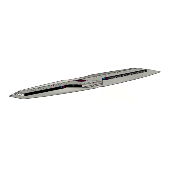
Introduction The SuperVisor™ is an interior lighting system that fits in the visor area near the top of the windshield. It delivers an amazing warning signal, including MR8 powered takedown lights. The SuperVisor is designed on a modular basis, which means that the light bar can be customized to meet most any requirements. -
Page 3: Unpacking & Pre-Installation
Unpacking & Pre-installation Carefully remove the SuperVisor™ and place it on a flat surface, taking care not to scratch the lenses or damage the cable coming out of the side. Examine the unit for transit damage, broken lamps, etc. Report any damage to the carrier and keep the shipping carton. - Page 4 Attach brackets to sun visor retaining clips In order to remove the sun visor retaining clip, unscrew the one torx screw holding it in place. Place the inner bracket on the retaining clip as shown in Figure 2. Attach the inner bracket and retaining clip to the headliner as illustrated in Figure 3. Do not completely tighten the screw at this time.
- Page 5 Attaching the pivot arm brackets Attach the outer brackets that are supplied noting the difference between passenger and driver side brackets. Position the driver's side bracket on the driver's side sun visor's pivot arm as shown in Figure 4. Attach the driver's side bracket to the headliner with the inner torx screw as shown in figure 5.
- Page 6 Before mounting the SuperVisor, apply gasket stripping to the front edge of the lower chassis in order to prevent scratching the windshield. See Figure 6. Once all four brackets and sun visors are attached, the SuperVisor is now ready to be installed. Position the SuperVisor in the center of the windshield as shown in Figure 7.
- Page 7 Mounting the SuperVisor™ (continued) The two center brackets should line up with the holes in the SuperVisor's lower chassis. Using the supplied 1/4"-20 bolts and the internal tooth lock washers, loosely install them as shown in Figure 8. FIGURE 8 Next, if necessary, slightly loosen the three pivot arm bracket retaining screws in order to align the pivot arm bracket's hole with the mating chassis hole on the end of the SuperVisor.
-
Page 9: Wiring Diagram & Instructions
Wiring Instructions Larger wires and tight connections will provide longer service life for components. For high current wires it is highly recommended that terminal blocks or soldered connections be used with shrink tubing to protect the connections. Do not use insulation displacement connectors (e.g. 3M Scotchlock type connectors). - Page 10 LED Fusing Considerations Although the average current draw per module is very low, due to the type of circuit used to power each module, the instantaneous peak current to a module can be significantly higher during low voltage conditions. To avoid prematurely blowing ATO style fuses or tripping breakers it is recommended the following rule-of-thumb be used to size fuses or breakers.
-
Page 11: Troubleshooting
Directional module Flash Pattern - Table 2 CycleFlash (DEFAULT) Quad Pop Flash75 NFPA QuadFlash75 Triple Pop Flash75 Steadyburn SingleFlash375 ModelFlash SingleFlash250 ActiveFlash SingleFlash150 FiveFlash70 FiveFlash150 QuadFlash70 QuadFlash150 TripleFlash70 DoubleFlash150 DoubleFlash70 TripleFlash150 SingleFlash75 Momentarily short and release to change patterns Flash Pattern Header for OPTIX/LEDX Troubleshooting All SuperVisors are thoroughly tested prior to shipment. -
Page 12: Parts List
Parts List Reference Number Part Description Part Number +12V Cooling Fan T05612 *LEDX LED Module *Contact Code 3, Inc for P/N MR8 lamp T09600 Chassis T09614 Outer Panel S51410 *Optix LED Module *Contact Code 3, Inc for P/N Not Shown Inner Mtg. - Page 13 Notes...
- Page 14 Notes...
- Page 15 Notes...
-
Page 16: Warranty
*Code 3, Inc. reserves the right to repair or replace at its discretion. Code 3, Inc. assumes no responsibility or liability for expenses incurred for the removal and /or reinstallation of products requiring service and/or repair.; nor for the packaging, handling, and shipping: nor for the handling of products returned to sender after the service has been rendered.
Need help?
Do you have a question about the SuperVisor and is the answer not in the manual?
Questions and answers