Table of Contents
Advertisement
Quick Links
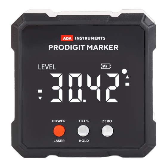
OPERATING MANUAL
PRODIGIT MARKER
Inclinometer
APPLICATION:
Control and measurement of slope of any surface. It is used in wood process-
ing industry (especially in furniture manufacturing industry) for wood angle
accurate cutting; auto repair industry for tiring assembling angle accurate con-
trolling; in machining industry for machine tool working angle accurate posi-
tioning; in woodwork; when setting guides for gypsum board partitions.
PRODUCT FEATURES:
─
Relative/absolute measurement interc hange at any position
─
Built-in magnets on measuring surface
─
Slope measurement in % and °
─
Power-off automatically in 3 minutes
─
Portable size, convenient to co-work with other measuring tools
─
HOLD data
─
2 built-in laser aimers
TECHNICAL PARAMETERS
Measuring range.......................... 4х90°
Resolution...................................... 0.05°
Accuracy......................................... ±0.2°
Battery............................................ Li-On battery, 3,7V
Working temperature................. -10°С ~50°
Dimension...................................... 561х61х32 mm
Laser aimers ................................. 635нм
Laser class ..................................... 2, <1mVt
FUNCTIONS
1. Laser line
2. ON/OFF the tool/laser
lines
3. HOLD data
Measuring units
3. HOLD data
2. Mode of the level
1. Measuring units
LI-ONBATTERY
Inclinometer operates from built-in Li-On battery. Battery level is shown on
the display. Blinking indicator (4) without inner bars shows low battery level.
For charging, connect the charger via USB type-C wire to the socket on the
back cover of the inclinometer. If the battery is fully charged, the indicator (4)
doesn't blink, all bars are filled.
NOTE! Do not use charger with output voltage more than 5V.
Higher voltage will damage the device.
OPERATION
1. Press «ON/OFF» button to switch ON the tool. The LCD displays absolute
hoprizontal angle. «Level» is displayed on the screen. Press «ON/OFF» button
againto switch off the tool.
2. If you lift the left side of the tool you will see an arrow "up" on the left side
of the display. On the right side of the display you will see an arrow "down". It
means the left side is higher and right side is lower.
3. Measurement of relative angles. Place the tool on the surface from which it is
necessary to measure the relative angle, press "ZERO" button. 0 is desplayed.
«Level» is not desplayed. Then place the tool on another surface. Value of the
relative angle is desplayed.
4. Press shortly «Hold/Tilt%» button to fix the value on the display. To continue
measurements repeat short pressing of «Hold/Tilt%» button.
5. Press «Hold/Tilt%» button for 2 sec to measure slope in %. To make angle
measurement in degrees, press and hold «Hold/Tilt%» button for 2 sec.
6. Use the laser lines to mark the level at a distance from inclinometer. Lines
can be used only for marking on vertical surfaces (such as walls) where the
level is attached to. Press ON/OFF button to swtich ON/OFF the tool and select
laser lines: right line, left line, both lines. Attach the tool to the vertical surface
and rotate it to the desired angle focusing on the data on the display. Mark the
inclination along laser lines on the vertical surface.
7. Magnets from all sides allow to attach the tool to the metal object.
8. "Err" is displayed on the screen, when the deviation is more than 45 degrees
from the vertical position. Return the instrument to the upright position.
CALIBRATION
1. Press and hold ZERO button to turn on the calibration mode. Then press
and hold ON/OFF button. Calibration mode is activated and "CAL 1" is dis-
played. Place the tool on a flat and smooth surface as shown in the picture.
2. Press ZERO button once in 10 seconds. "CAL 2" wil be displayed. Rotate the
tool by 90 degrees in clockwise direction. Place it on the right edge towards
display.
3. Press ZERO button once in 10 seconds. "CAL 3" wil be displayed. Rotate the
tool by 90 degrees in clockwise direction. Place it on the upper edge towards
display.
4. Press ZERO button once in 10 seconds. "CAL 4" wil be displayed. Rotate the
tool by 90 degrees in clockwise direction. Place it on the left edge towards
display.
5. Press ZERO button once in 10 seconds. "CAL 5" wil be displayed. Rotate the
tool by 90 degrees in clockwise direction. Place it on the lower edge towards
display.
1. Laser line
6. Press ZERO button once in 10 seconds. "PASS" wil be displayed. After a while
"0.00 degrees" will be also displayed. The calibration is over.
4. Relative angle
4. Power indication
5. Direction of the inclina-
tion
1.
2.
3.
4.
5.
SAFETY OPERATION INSTRUCTIONS
IT IS FORBIDDEN:
•
•
press ZERO in 10 min.
rotate the device
press ZERO in 10 min.
rotate the device
press ZERO in 10 min.
Use a charger with an output voltage of more than 5 V to charge the
battery of the device.
Use of the device not according to the instructions and use that goes
beyond the permitted operations;
adainstruments.com
6.
rotate the device
7.
press ZERO in 10 min.
8.
rotate the device
9.
press ZERO in 10 min.
10. calibration is over
Advertisement
Table of Contents

Related Manuals for ADA INSTRUMENTS PRODIGIT MARKER


Summary of Contents for ADA INSTRUMENTS PRODIGIT MARKER
- Page 1 On the right side of the display you will see an arrow “down”. It means the left side is higher and right side is lower. PRODIGIT MARKER 3. Measurement of relative angles. Place the tool on the surface from which it is necessary to measure the relative angle, press “ZERO”...
- Page 2 • Use of the device in an explosive environment (gas station, gas equipment, WARRANTY CARD chemical production, etc.); • Disabling the device and removing warning and indicative labels from the Name and model of the product ______________________________________________ device; • Opening the device with tools (screwdrivers, etc.), changing the design of Serial number ___________________ Date of sale ______________________________ the device or modifying it.
Need help?
Do you have a question about the PRODIGIT MARKER and is the answer not in the manual?
Questions and answers