Sign In
Upload
Manuals
Brands
Rohde & Schwarz Manuals
Inverter
R&S SMU200A
Rohde & Schwarz R&S SMU200A Manuals
Manuals and User Guides for Rohde & Schwarz R&S SMU200A. We have
6
Rohde & Schwarz R&S SMU200A manuals available for free PDF download: Manual, Operating Manual, Service Manual, Quick Start Manual, Application Note
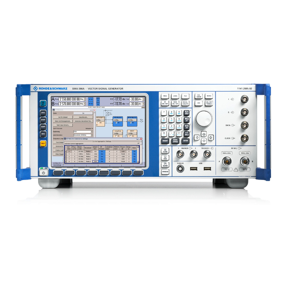
Rohde & Schwarz R&S SMU200A Manual (1929 pages)
Vector Signal Generator
Brand:
Rohde & Schwarz
| Category:
Inverter
| Size: 19 MB
Table of Contents
Contents - Chapter 1 "Putting into Operation"
24
Customer Support
18
Quick Start Guide
20
Table of Contents
24
Chapter 1: Putting into Operation
25
Putting into Operation
26
Introduction - Putting into Operation
26
Legend for Front Panel View
26
Chapter 3: Operation
34
Legend for Rear Panel View
36
Putting into Operation
41
Setting up the Instrument or Installing It in a 19" Rack
41
Unpacking the Instrument
41
EMC Safety Precautions
42
General Precautions
42
Safety Instructions
42
Connecting the R&S SMU to the AC Supply
43
Switching on
43
Start Display and Booting the R&S SMU
44
Switching off
44
Default Settings
45
Function Check
45
Windows XP Embedded
46
Connecting an External Keyboard
47
Connecting the Mouse
47
Connecting an External Monitor
48
Connecting the R&S SMU to a Network (LAN)
49
Connection to the Network
49
Configuration for Manual Remote Control Via Windows Remote Desktop Connection
57
Manual Remote Control Via an External Controller
57
Configuration for Manual Remote Control Via Ultr@Vnc
62
Preparing the Installation of Norton Antivirus
69
Using Norton Antivirus
69
Contents - Chapter 2 "Getting Started"
74
Chapter 2 Getting Started
76
Introduction - Getting Started
76
Baseband Section of R&S SMU
80
RF Section of R&S SMU
81
Applications of the Two-Path R&S SMU
82
Two Baseband Generators, One RF Path
82
One Baseband Path and Two RF Paths
83
Fully Equipped Two-Path Instrument
84
Available Blocks
85
Blocks of the Baseband Section
85
Description of Individual Diagram Blocks
85
Blocks of the RF Section
88
Example of Setup
90
Contents - Chapter 3 "Manual Operation"
98
Introduction - Manual Operation
100
Manual Operation
100
Operating Concept
100
Display
106
Frequency and Level Setting - Display
106
Status Information and Messages - Display
107
Info Window - Display
108
Block Diagram - Display
109
Winbar and Softkeys - Display
111
Menu Structure - Display
112
Graphical Display of Output Signal Characteristics
115
Calling a Menu - Setting Parameters
116
Setting Parameters
116
Selecting a Control Element - Setting Parameters
117
Switching Parameters On/Off - Setting Parameters
117
Selecting and Exiting a Menu Area - Setting Parameters
118
Entering a Value - Setting Parameters
119
Selecting a Unit - Setting Parameters
121
Selecting a Value from a List - Setting Parameters
122
Terminating Entries - Setting Parameters
123
Restoring the Previous Value - Setting Parameters
124
Menu Operation
125
Editors
126
List Editor
126
Data Editor
128
Control and Marker List Editor
130
Help System
134
File Management
136
File Select Menu
137
File Manager
138
Manual Remote Control
141
Legend of Front-Panel Controls
142
Overvoltage Protection
248
Operating Modes
275
Control Signals
383
Chapter 6: Remote Control - Description of Commands
1062
Chapter 8: Maintenance and Interfaces
1862
Chapter 9: Error Messages
1876
Index
1881
Re E-2
1887
Advertisement
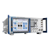
Rohde & Schwarz R&S SMU200A Operating Manual (888 pages)
Vector Signal Generator
Brand:
Rohde & Schwarz
| Category:
Inverter
| Size: 15 MB
Table of Contents
Table of Contents
23
Customer Support
21
1 Preface
35
Conventions Used in the Documentation
36
2 Preparing for Use
39
Utility Keys
40
Display
41
Display Keys
42
Keypad for Data Entry
43
Rotary Knob and Navigation Keys
44
Front Panel Connectors
45
Rear Panel Tour
47
Description of the Connectors
48
Putting into Operation
51
Unpacking and Checking the Instrument
53
Connecting the Instrument to the AC Supply
54
Standby and Ready State
55
Function Check
56
Shutting down the Instrument
58
Connecting a Monitor
60
Setting up a Network (LAN) Connection
62
Connecting the Instrument to the Network
63
Assigning the IP Address
64
Using Computer Names
65
Working with Directories
66
Using a Web Browser for Remote Access
68
Remote Desktop Connection
69
Remote Access Via Ultr@Vnc
71
Using Virus-Protection Software
77
LXI Configuration
78
LXI Browser Interface
80
LAN Configuration
81
Advanced LAN Configuration
82
Ping
83
3 Getting Started
85
Applications of the Instrument
87
Two Baseband Generators, One RF Path
89
One Baseband Path and Two RF Paths
90
Fully Equipped Two-Path Instrument
91
Description of Individual Diagram Blocks of the Baseband Section
93
RF Section
95
Attenuator Settings
96
Example of Setup
97
4 Manual Operation
105
Display
109
Settings Displayed in the Header Section
110
Status Information and Messages
111
Permanent Messages
112
Block Diagram
113
Signal Flow and Input/Output Symbols in the Block Diagram
114
Winbar and Softkeys
115
Graphical Display of Output Signal Characteristics
116
Setting Parameters
118
Working with the Cursor
119
Entering a Value
120
Working with Units
122
Terminating Entries with Confirmation
123
Restoring the Previous Value
124
Editors
125
Working with Data Editor
126
Working with Control and Marker List Editor
128
How to Use the Help System
131
File Management
133
File Select Dialog
135
File Manager
136
Extensions for User Files
137
Legend of Front-Panel Controls
139
Front Panel Key Emulation
141
On-Screen Keyboard
142
Internal Adjustments
148
Hardware Config
150
Software / Options
151
Gui Update
152
Install SW-Option
153
Update
154
Selftest
155
Check Front Panel
156
5 Instrument Function
143
General Instrument Settings
146
General Configuration of Instrument - Setup Key
147
Global Trigger/Clock/External Input Settings
157
Display/Keyboard Settings
159
User Marker / aux I/O Settings
160
Remote Channel Settings
164
Protection
166
Save/Recall
168
Help
169
Generating a Hard Copy of the Display
170
Hardcopy Dialog
171
Hardcopy Options
172
Messages - Info Key
175
Storing and Loading Instrument Data - File Key
176
File Menu
177
Loading Instrument Settings
179
File Manager
180
Graphical Display - Graphics
182
Graphics Settings Menu
183
Bar of Graphics Window
186
Signal Displays
188
Vector Diagram
189
Constellation Diagram
190
Eye Diagram
191
CCDF Display
192
Power Spectrum
193
Bit and Block Error Rate Measurements - BERT Block
194
Test Setup
195
PRBS Data
196
Ending the Measurement
197
Data Enable
198
Pattern Ignore
199
General Settings
200
Configuration
203
Block Error Rate Menu
208
General Settings
209
Configuration
211
RF Signal and Analog Modulations - RF Block
214
Overview of the RF Signal Settings
215
RF Frequency Settings
216
Configuring RF Frequency
217
Phase Settings
219
Phase Continuous Frequency Setting
220
Reference Oscillator
224
Local Oscillator - lo Coupling
226
Typical Applications
227
LO Coupling Menu
228
NRP-Z Power Viewer
230
NRP-Z Power Viewer Menu
231
RF Level/Emf
236
RF Level
237
Power-On/Emf Settings
240
Automatic Level Control - ALC
241
Automatic Level Control Menu
242
User Correction
243
Multi Level Measurements Allow to Take into Account the Changing VSWR for the Different
244
User Correction Menu
244
Filling the Correction List Automatically
249
Filling the Correction List with Power Sensor Measurement Data
250
Overvoltage Protection
252
Analog Modulations
253
Amplitude Modulation (AM)
254
Broadband Amplitude Modulation (BB-AM)
257
Frequency Modulation (FM)
258
Phase Modulation (Phim)
261
Pulse Modulation (PM)
264
LF Generator and LF Output - Mod Gen
266
Sweep Mode
267
RF Frequency Sweep
268
RF Level Sweep
274
LF Frequency Sweep
281
List Mode
286
List Mode Dialog
287
Filling the List Mode Data Automatically
294
I/Q Modulation - I/Q Mod Block
295
I/Q Modulator
297
General I/Q Mod Settings
298
Impairements
299
I/Q Swap and I/Q Wideband
305
Analog Wideband I/Q Input
306
Impairment of Digital I/Q Signal and Noise Generator - AWGN/IMP Block
308
Impairments
309
AWGN - Noise Generator
320
AWGN Settings Dialog
321
Output of the Baseband Signal - I/Q out
328
Analog I/Q Output
329
Digital I/Q Output Settings
333
I/Q Level - Info
337
Baseband Signal Level
338
Baseband Signal Level Measurement
339
Baseband Signal - Baseband Block
341
Working with the Baseband Signal
342
Data and Signal Sources in Baseband
347
Internal PRBS Data and Data Patterns
348
External Synchronous Modulation Data
349
Clock Signals
350
Synchronizing Data Signals and Clock Signals
351
Control Signals
354
Trigger Signals
356
Marker Output Signals
357
Overview and Required Options
358
Coding - Custom Digital Mod
362
Baseband Filter - Custom Digital Mod
365
Conflicting Settings - Custom Digital Mod
367
Custom Digital Mod User Interface
368
Arbitrary Waveform Generator ARB
396
ARB User Interface
400
Multi Segment Waveforms
421
Multi Carrier Waveforms
432
Multi Carrier Continuous Wave
442
External Baseband Signal - Baseband Input
456
BB Input Block
457
Baseband Input Settings Menu
458
Signal Routing and Frequency Shifting
464
6 Remote Control Basics
469
VISA Libraries
470
LAN Interface
471
VXI-11 Protocol
472
GPIB Interface (IEC/IEEE Bus Interface)
473
GPIB Instrument Address
474
Starting a Remote Control Session
475
Returning to Manual Operation
476
Examples
477
Remote Control over LAN Using VXI-11 Protocol
478
Remote Control over LAN Using Socket Communication
481
SCPI Command Structure
488
Syntax for Device-Specific Commands
489
SCPI Parameters
491
Overview of Syntax Elements
494
Responses to Queries
495
Command Sequence and Synchronization
496
Preventing Overlapping Execution
497
Status Reporting System
499
Structure of a SCPI Status Register
501
Contents of the Status Registers
502
IST Flag and Parallel Poll Enable Register (PPE)
503
Application of the Status Reporting System
504
Service Request
505
Query of an Instrument Status
506
General Programming Recommendations
507
7 Remote Control Commands
509
Cal
509
Cls
510
Ese
510
Esr
510
Idn
510
Ist
511
Opc
511
Opt
511
Pcb
511
Pre
512
Psc
512
Rcl
512
Rst
512
Sav
513
Sre
513
Stb
513
Trg
513
Tst
513
Wai
514
Preset Commands
514
7.3 R&S Signal Generator Waveform and List Format
516
R&S Signal Generator Waveform and List Format
516
TYPE: Magic, XXXXXXXX
517
CLOCK: Frequency
518
COMMENT: String
519
COPYRIGHT: String
519
DATA BITLENGTH: Bitlength
519
CONTROL LENGTH: Controllength
520
DATA LIST-Length: #D0D1
520
DATE: Yyyy-MM-DD;Hh:MM:ss
520
LEVEL OFFS: Rmsoffset_Db,Peakoffset_Db
521
SAMPLES: Samples
522
[TRACE] LIST [#]: Pos0:Val0;Pos1:Val1
522
WAVEFORM-Length: #I0Q0I1Q1
524
MWV_SEGMENT_COUNT: Numofseg
525
MWV_SEGMENT_CLOCK_MODE: Mode
526
MWV_SEGMENT_LENGTH: Samplesseg0, Samplesseg1
526
MWV_SEGMENT_START: Samplestartoffsetseg0, Samplestartoffsetseg1
526
Samplestartoffsetsegn-1
526
MWV_SEGMENT_CLOCK: Clockseg0, Clockseg1
527
Mwv_Segmentx_Comment: Text
528
MWV_SEGMENT_FILES: "Filenameseg0.Wv", "Filenameseg1.Wv
528
Filenamesegn-1.Wv
528
MWV_SEGMENT_LEVEL_OFFS: Rmsoffset_Dbseg0, Peakoffset_Dbseg0
528
Rmsoffset_Dbsegn-1, Peakoffset_Dbsegn-1
528
CONTROL LIST WIDTH4-Length: #M0M1
529
Creating a Waveform Manually
529
7.4 Bert and Bler Subsystems
533
Bler:result
533
BERT and BLER Subsystems
533
Bert:result
534
Bert:sequence
536
Bert:setup:clock[:Polarity]
536
Bler:sequence
536
Bler:setup:clock[:Polarity]
536
Bler:setup:corder
536
Bert:setup:data[:Polarity]
537
Bert:setup:denable
537
Bler:setup:data[:Polarity]
537
Bler:setup:denable
537
Bert:setup:ignore
538
Bler:setup:mcount
538
Bert:setup:mcount
539
Bert:setup:merror
539
Bert:setup:restart:state
539
Bler:setup:merror
539
Bert:setup:type
540
Bler:setup:type
540
Bert:start
541
Bert:state
541
Bert:stop
541
Bler:start
541
Bler:state
541
Bler:stop
541
Bert:unit
542
Bler:unit
542
[:Source]:Input:bert:impedance
542
[:Source]:Input:bert:threshold
542
7.5 Calibration Subsystem
543
Calibration:all[:Measure]
543
Calibration Subsystem
543
Trigger:bert[:Immediate]
543
Trigger:bler[:Immediate]
543
Calibration<Hw>:Bbin[:Measure]
544
Calibration<Hw>:Fmoffset[:Measure]
544
Calibration<Hw>:Frequency[:Measure]
544
Calibration<Hw>:Iqmodulator:full
545
Calibration<Hw>:Iqmodulator:local
545
Calibration<Hw>:Level[:Measure]
545
Calibration<Hw>:Level:haccuracy[:State]
546
Clock Subsystem
546
Diagnostic Subsystem
547
Display Subsystem
549
Format Subsystem
550
Calibration<Hw>:Level:state
546
7.10 Hcopy Subsystem
552
Hcopy Subsystem
553
Hcopy:data
553
Hcopy:device:language
553
Hcopy:file[:Name]
554
Hcopy:file[:Name]:Auto
554
Hcopy[:Execute]
554
Hcopy:file[:Name]:Auto:directory
555
Hcopy:file[:Name]:Auto:directory:clear
555
Hcopy:file[:Name]:Auto:file
555
Hcopy:file[:Name]:Auto[:File]:Day
556
Hcopy:file[:Name]:Auto[:File]:Month
556
Hcopy:file[:Name]:Auto[:File]:Number
557
Hcopy:file[:Name]:Auto[:File]:Prefix
557
Hcopy:file[:Name]:Auto[:File]:Year
558
Hcopy:image:format
558
Hcopy:printer:list
559
Hcopy:printer:page:margins
559
Kboard Subsystem
560
Mmemory Subsystem
561
File Naming Conventions
562
Extensions for User Files
563
Hcopy:printer[:Name]
559
7.12.3 Remote Control Commands
565
Remote Control Commands
565
Mmemory:catalog:length
566
Mmemory:cdirectory
567
Mmemory:dcatalog
568
Mmemory:dcatalog:length
569
Mmemory:load:state
569
Mmemory:mdirectory
570
Mmemory:rdirectory
571
Mmemory:store:state
571
7.13 Output Subsystem
572
Output<Hw>:Afixed:range:lower
572
Output Subsystem
572
Output<Hw>:Afixed:range:upper
573
Output<Hw>:Amode
573
Output:blank:polarity
574
Output<Hw>:Blank:list:state
574
Output<Hw>:Impedance
575
Output<Hw>:Protection:clear
575
Output<Hw>:Protection:state
575
Output<Hw>:Protection:tripped
576
Output<Hw>[:State]
576
Output<Hw>[:State]:Pon
576
Output:user<Ch>:Source
577
Sense, READ and Initiate Subsystems
577
Table of Contents
578
Sense<Ch>[:Power]:Display:permanent:priority
579
Sense<Ch>[:Power]:Filter:length:auto
580
Sense<Ch>[:Power]:Filter:length[:User]
580
Sense<Ch>[:Power]:Filter:nsratio
581
Sense<Ch>[:Power]:Filter:nsratio:mtime
581
Sense<Ch>[:Power]:Filter:sonce
581
Sense<Ch>[:Power]:Filter:type
582
Sense<Ch>[:Power]:Frequency
582
Sense<Ch>[:Power]:Offset
583
Sense<Ch>[:Power]:Offset:state
583
Sense<Ch>[:Power]:Snumber
583
Sense<Ch>[:Power]:Source
584
Sense<Ch>[:Power]:Status[:Device]
584
Sense<Ch>[:Power]:Sversion
584
Sense<Ch>:Unit[:Power]
585
Source Subsystem
586
Source:am Subsystem
587
Source:awgn Subsystem
589
Source:bb Subsystem
598
Sense<Ch>[:Power]:Type
585
Sense<Ch>[:Power]:Zero
585
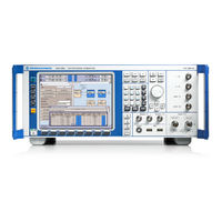
Rohde & Schwarz R&S SMU200A Manual (510 pages)
Vector Signal Generator
Brand:
Rohde & Schwarz
| Category:
Portable Generator
| Size: 7 MB
Table of Contents
Contents - Chapter 1 "Putting into Operation"
16
Table of Contents
16
Putting into Operation
18
Introduction - Putting into Operation
18
Legend for Front Panel View
18
Legend for Rear Panel View
28
Putting into Operation
32
Unpacking the Instrument
32
Setting up the Instrument or Installing It in a 19" Rack
32
Safety Instructions
33
EMC Safety Precautions
33
Connecting the R&S SMU to the AC Supply
34
Switching on
34
Start Display and Booting the R&S SMU
35
Switching off
35
Function Check
36
Default Settings
36
Windows XP Embedded
37
Connecting an External Keyboard
38
Connecting the Mouse
38
Connecting an External Monitor
39
Connecting the R&S SMU to a Network (LAN)
40
Connection to the Network
40
Configuration for Manual Remote Control
46
Contents - Chapter 2 "Getting Started"
50
Getting Started
52
Introduction - Getting Started
52
Baseband Section of R&S SMU
55
RF Section of R&S SMU
56
Applications of the Two-Path R&S SMU
57
Two Baseband Generators, One RF Path
57
One Baseband Path and Two RF Paths
58
Fully Equipped Two-Path Instrument
59
Available Blocks
60
Blocks of the Baseband Section
60
Description of Individual Diagram Blocks
60
Blocks of the RF Section
62
Example of Setup
64
Contents - Chapter 3 "Manual Operation"
72
Introduction - Manual Operation
74
Manual Operation
74
Operating Concept
74
Display
80
Frequency and Level Setting - Display
81
Status Information and Messages - Display
81
Info Window - Display
82
Block Diagram - Display
84
Winbar and Softkeys - Display
86
Menu Structure - Display
87
Graphical Display of Output Signal Characteristics
90
Calling a Menu - Setting Parameters
91
Setting Parameters
91
Selecting a Control Element - Setting Parameters
93
Switching Parameters On/Off - Setting Parameters
93
Selecting and Exiting a Menu Area - Setting Parameters
94
Entering a Value - Setting Parameters
96
Selecting a Unit - Setting Parameters
97
Selecting a Value from a List - Setting Parameters
99
Terminating Entries - Setting Parameters
100
Restoring the Previous Value - Setting Parameters
101
Menu Operation
102
Help System
111
File Management
113
File Select Menu
114
Manual Remote Control
118
Legend of Front-Panel Controls
120
Menus
122
Root Menu Level
122
Second Menu Level
122
Contents - Chapter 4 "Instrument Functions"
124
Instrument Functions
130
Overview of Instrument Functions
130
Default Instrument Settings - Preset Key
132
General Instrument Settings
132
Overview of General Instrument Settings
132
General Configuration of Instrument - Setup Key
133
Internal Adjustments - Setup-System
133
Hardware Config
135
Gui Update
136
Software / Options
137
Install SW-Option
139
Test Point
139
Check Front Panel - Setup-Test
140
Global Trigger/Clock/External Input Settings - Setup-Environment
141
User Marker - aux IO - Setup-Environment-Global
143
Protection - Setup-Protection
146
Remote GPIB - Setup-Remote
146
Save Recall - Setup-Setting
146
Generating a Hardcopy of Display - Hcopy Key
147
Help - Setup-Help
147
Switching to Manual Control - Local Key
147
Help System - Help Key
148
Messages - Info Key
148
Storing and Loading Instrument Data - File Key
150
File Menu
151
Storing Instrument Settings - File
151
Loading Instrument Settings - File
153
File Management - File
155
Graphical Display - Graphics
157
Graphical Display of Signal Characteristics
157
Graphics Settings Menu
158
Softkey Bar of Graphics Window
160
I/Q Diagram - Graphics
163
Signal Displays - Graphics
163
Vector Diagram - Graphics
164
Constellation Diagram - Graphics
165
Eye Diagram - Graphics
166
CCDF Display - Graphics
167
Power Spectrum - Graphics
168
Overview of RF Signal and Analog Modulations
169
RF Signal and Analog Mod - a Mod-RF
169
RF Frequency and Phase - Frequency - Phase
170
Frequency - Phase Menu
171
Reference Oscillator Menu
173
RF Reference Frequency - Reference Oscillator
173
RF Level - Level - EMF
175
Level - EMV Menu
176
Automatic Level Control - ALC
179
Automatic Level Control Menu
180
User Correction
181
User Correction Menu
181
Overvoltage Protection
184
List Mode - List
185
Frequency Sweep Menu
191
Sweep Mode
191
Level Sweep Menu
196
LF Frequency Sweep Menu
200
LF Generator and LF Output - LF Output
204
LF Output Menu
204
Analog Modulations
205
Modulation Sources
205
Simultaneous Operation of Several Modulations or Other Operating Modes
205
Amplitude Modulation - am
206
Amplitude Modulation Menu
206
Broadband Amplitude Modulation - BB-AM
208
Broadband Amplitude Modulation Menu
208
Pulse Modulation
210
Pulse Modulation Menu
210
I/Q Modulation
212
Introduction - I/Q Modulation
212
I/Q Modulator - I/Q MOD Function Block
213
I/Q Settings Menu
213
Fig. 4-1 Definition of IQ Modulator in IS2000 and R&S SMU
218
Impairment of Digital I/Q Signal and Noise Generator - AWGN-IMP Block
221
Introduction - Impairments and AWGN
221
Impairment Settings Menu
222
Introduction - Impairments
222
AWGN Settings Menu
228
Introduction - Noise Generator - AWGN
228
Bit and Block Error Rate Measurements - BERT Block
233
Introduction - Bit and Block Error Rate Measurements
233
Fig. 4-2 Test Setup for Bit or Block Error Rate Measurement
234
Fig. 4-6 Data Enable Signal with Block Error Rate Measurement
236
Bit Error Rate Menu
237
Block Error Rate Menu
247
Baseband Signal - Baseband
254
Introduction - Baseband Signal
254
Signal Routing and Frequency Shifting
254
Data and Signal Sources in Baseband
259
Fig. 4-8 9-Bit PRBS Generator
260
Internal PRBS Data and Data Patterns
260
External Serial Modulation Data Via the DATA Connector
261
External Synchronous Modulation Data
261
Internal Modulation Data from Lists
261
External Asynchronous Modulation Data
262
External Parallel Modulation Data Via the aux I/O Interface
262
Clock Signals
263
Fig. 4-10 Data and Clock Output Signals on the Parallel aux I/O Interface
264
Internal Clock and Internal Data
264
Synchronizing Data Signals and Clock Signals
264
Fig. 4-11 External Serial Data and the Clock Signals
265
Fig. 4-12 External Parallel Data, Internal Clock Signal and the Clock Signal
265
Internal Clock and External Synchronous Data
265
External Clock and External Synchronous Data
266
External Clock and Internal or External Asynchronous Data
266
Fig. 4-13 External Serial Data and External Symbol Clock
266
Fig. 4-14 External Parallel Data
266
Control Signals
267
Power Ramping and Level Attenuation
267
Fig. 4-15 Signal Behaviour When Power Ramping Is Enabled
268
Trigger Signals
268
Marker Output Signals
269
Digital Modulation - Custom Digital Modulation
270
Introduction - Custom Digital Modulation
270
Modulation Types - Custom Digital Mod
270
Coding - Custom Digital Mod
273
Baseband Filter - Custom Digital Mod
276
Conflicting Settings - Custom Digital Mod
277
Custom Digital Mod Menu
278
List Management - Digital Modulation Menu
287
Data List Editor - Digital Modulation
290
Control and Marker List Editor - Digital Modulation
292
Power Ramp Control - Digital Modulation Menu
296
Trigger/Marker/Clock - Custom Digital Modulation Menu
299
Arbitrary Waveform Generator ARB
306
ARB Menu
308
Trigger/Marker/Clock - ARB MOD Menu
311
Sine Test Signals - ARB MOD Menu
318
Introduction - Multicarrier CW
320
Multicarrier Continuous Wave
320
Trigger/Marker/Clock Menu - Multicarrier CW
327
Digital Standard GSM/EDGE
333
Introduction - Digital Standard GSM/EDGE
333
GSM/EDGE Menu
334
Mode Unframed - GSM/EDGE
339
Mode Framed (Single) - GSM/EDGE
341
Mode Framed (Double) - GSM/EDGE
343
Save Recall Frame/Slots - GSM/EDGE
344
Modulation - GSM/EDGE
348
Power Ramping - GSM/EDGE
350
Trigger/Marker/Clock - GSM/EDGE
353
Burst Editor - GSM/EDGE
361
Slot Marker Definition - GSM/EDGE
372
Digital Standard 3GPP FDD
375
Introduction - Digital Standard 3GPP FDD
375
Downlink Scrambling Code Generator
377
Fig. 4-16 Components of the 3GPP FDD Transmission System
377
Modulation System 3GPP FDD
377
Scrambling Code Generator
377
Fig. 4-17 Structure of Downlink Scrambling Code Generator
378
Uplink Scrambling Code Generator
378
Fig. 4-18 Structure of Uplink Short Scrambling Code Generator
379
Channelization Code Generator
380
Fig. 4-19 Constellation Diagram of a Channel with 0 Db Power
380
Scrambling Unit
380
Data Source
381
Slot and Frame Builder
381
Demultiplexer - 3GPP FDD
382
Power Control - 3GPP FDD
382
Timing Offset
382
Fig. 4-20 Constellation Diagram of a Channel with -6 Db Power
383
Fig. 4-21 Constellation Diagram of a 3GPP W-CDMA Signal with Two DPCH Channels
383
Multicode - 3GPP FDD
383
Summation and Filtering - 3GPP FDD
383
3GPP FDD Menu
384
Filtering, Clipping, ARB Settings - 3GPP FDD
397
Fig. 4-22 Constellation Diagram of the Signal Without Clipping
399
Fig. 4-23 Constellation Diagram with Clipping Level 50 %, Vector Mode (|I+Q|)
399
Fig. 4-24 Constellation Diagram of the Signal with 4 DPCH Without Clipping
400
Trigger/Marker/Clock - 3GPP FDD
401
Test Setups - Models - 3GPP FDD
407
Predefined Settings - Downlink - 3GPP FDD
410
Additional User Equipment - Uplink - 3GPP FDD
412
Base Station Configuration - 3GPP FDD
413
Compressed Mode - BS - 3GPP FDD
415
Compressed Mode Configuration Graph - BS - 3GPP FDD
418
Fig. 4-25 Envelope of Compressed Mode Signal with Double-Frame Method
419
Fig. 4-26 Envelope of Compressed Mode Signal with Double-Frame Method
419
Code Domain Graph - BS - 3GPP FDD
420
Fig. 4-27 Code Tree of Channelization Codes
420
Multi Channel Assistant - BS - 3GPP FDD
420
Channel Graph - Base Station - 3GPP FDD
424
Channel Table - BS - 3GPP FDD
425
Fig. 4-28 Structure of a Downlink DPCH in the Time Domain
427
Enhanced Settings for P-CCPCH - BS1 - 3 GPP FDD
432
Channel Coding - Enhanced PCCPCH BS1 - 3GPP FDD
433
Fig. 4-29 Generation of a Channel Coded P-CCPCH/BCH
433
Enhanced Settings for Dpchs - BS1 - 3GPP FDD
434
Channel Coding - Enhanced Dpchs BS1 - 3GPP FDD
436
Fig. 4-30 Channel Coding of the 12.2 Kbps Reference Measurement Channel (Downlink)
436
Transport Channel - Enhanced Dpchs BS1 - 3GPP FDD
440
Error Insertion - Enhanced Dpchs BS1 - 3GPP FDD
443
Fig. 4-31 Dynamic Power Control - down Link
445
DPCCH Settings - BS Channel Table 3GPP FDD
448
Fig. 4-32 Dynamic Change of Channel Power (Continuous)
451
Multi Channel Assistant - BTS 3GPP FDD
453
User Equipment Configuration (UE) - 3GPP FDD
456
Common Settings - UE - 3GPP FDD
458
Compressed Mode - User Equipment - 3GPP FDD
460
Compressed Mode Configuration Graph - User Equipment - 3GPP FDD
462
Fig. 4-33 Envelope of Compressed Mode Signal with Double-Frame Method
463
Fig. 4-34 Envelope of Compressed Mode Signal with Double-Frame Method
463
PRACH Settings - UE - 3GPP FDD
464
Channel Coding State - PRACH UE 1 - 3GPP FDD
470
PCPCH Settings - UE - 3GPP FDD
471
Channel Coding - PCPCH UE - 3GPP FDD
478
DPCCH Settings - UE - 3GPP FDD
479
Fig. 4-35 Structure of an Uplink DPCH in the Time Domain
479
Fig. 4-36 Dynamic Change of Channel Power (Continuous)
482
DPDCH Settings - UE - 3GPP FDD
483
Global Enhanced Channel Settings - UE1 - 3GPP FDD
488
Channel Coding - DPDCH Enhanced UE 1 - 3GPP FDD
489
Fig. 4-37 Channel Coding of the 12.2 Kbps Reference Measurement Channels (Uplink)
489
Show Details - DPDCH Enhanced UE1 - 3GPP FDD
491
Transport Channel - DPDCH Enhanced UE1 - 3GPP FDD
493
Error Insertion - DPDCH Enhanced UE1 - 3GPP FDD
496
Dynamic Power Control - DPDCH Enhanced User Equipment - 3GPP FDD
497
Advertisement
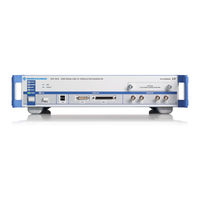
Rohde & Schwarz R&S SMU200A Service Manual (294 pages)
Vector Signal Generator
Brand:
Rohde & Schwarz
| Category:
Portable Generator
| Size: 16 MB
Table of Contents
Contents - Chapter 1 "Performance Test"
27
Table of Contents
27
1 Checking the Rated Characteristics
28
Measuring Equipment and Accessories
28
Test Assemblies
30
Standard Test Assembly for Analog Modulations
30
Test Assembly for Residual
30
Test Assembly for I/Q Modulation
31
Test Assembly for SSB Phase Noise
31
Test Assembly for Output Impedance (VSWR)
32
Test Assembly for Settling Time
32
Test Assembly for Settling Time with Fast Hopp Bus
33
Preparation, Recommended Test Frequencies and Levels
35
Test Procedures
36
Reference Frequency
36
Frequency
37
Spectral Purity
39
Level Data
48
Internal Modulation Generator
54
Amplitude Modulation
56
Frequency Modulation (Option R&S B20/B22)
59
Phase Modulation (Option R&S B20/B22)
65
Pulse Modulation
67
I/Q Modulation
69
Broadband Amplitude Modulation
74
Baseband Input (Option R&S B17)
75
Differential I/Q Output (Option R&S B16)
80
Baseband Digital IQ-Output (Option R&S -B18)
83
Internal Baseband Generator
84
Digital Standard GPS (R&S K44)
101
3 Gpp Fdd Hsupa (R&S K45)
101
Digital Standard CDMA2000 (R&S K46)
101
Digital Standard Wimax 802.16-2004 (R&S K49)
101
Digital Standard WLAN 802.11 A, B, G (R&S K48)
101
Digitaler Standard TD-SCDMA (R&S K50)
101
TD-SCDMA Enhanced BS/MS Tests (R&S K51)
101
Fader and Fader Extension (R&S B14 / B15)
102
Additive White Gaussian Noise (R&S K62)
104
Bit Error Rate Tester (BER, Option R&S K80)
105
Hardware Signals (Only R&S SMATE)
105
Testing with Option B90 (Mimo) Enabled
106
Tests Extended for B90
108
Baseband Digital IQ-Output (Option R&S SMU/SMJ-B18)
111
Internal Baseband Generator
112
Contents - Chapter 3 "Repair"
125
Repair
128
Instrument Design and Function Description
128
RF-Section
128
Standard Synthesis Module SSYN
128
Synthesis Extension Module SYNEX
130
IQ Output Module 3Ghz IQOP3
131
IQ Output Module 6Ghz IQOP6
133
Attenuators 3 Ghz SATT3 and 6 Ghz SATT6
134
High-Power Output (Option for SATT3 and SATT6)
134
Electronic Attenuator 6 Ghz SATT6C
135
Overvoltage Protection (Option for SATT3)
135
Baseband Section
135
Data Transfer
135
IQ Bridge
135
DAC Interface DACIF
136
DAC Board
137
Universal Coder UNICOD
138
Fading Simulator (FADER) and Fading Simulator Extension (FADEX)
139
Power Supply Module
140
Front Module Controller
140
Motherboard
140
Troubleshooting
141
Measuring Equipment and Accessories
141
Switch-On Problems
142
Problems with Booting
145
Keyboard and Rotary Knob Test
149
A Baseband Module Can Not be Operated
150
Troubleshooting with Test Points and Debug Page
150
Troubleshooting with Internal Adjustments
151
Faulty RF Output Signal
153
Level Errors
154
Faulty I/Q Modulation
155
Faulty
156
Faulty Pulse Modulation
157
Faulty Signal Generation in the Baseband
158
Troubleshooting - Module SSYN
160
Internal Adjustment "Adjust Synthesis
160
Input and Output Signals
160
Error Messages Concerning the Module SSYN
161
Error Message - DACIF: PLL Unlocked (100 Mhz)
162
Frequency Error < 2*10 -6 , Reference Oscillator Adjustment
162
Error Messages Concerning the Module SYNEX
163
Input and Output Signals
163
Internal Adjustment "Adjust Synthesis
163
Troubleshooting - Module SYNEX
163
Error Message - DACIF: PLL Unlocked (100 Mhz)
164
Frequency Error < 2*10 -6 , Reference Oscillator Adjustment
164
Input and Output Signals
165
Internal Adjustments "Adjust Level", "Adjust I/Q Modulator
165
Troubleshooting - Module IQOP3
165
Error Messages Concerning the Module IQOP3
166
Tests on Submodule IOQOP3 LCM
167
Input and Output Signals
170
Internal Adjustments , Adjust I/Q Modulator
170
Troubleshooting - Module IQOP6
170
Error Messages Concerning the Module IQOP6
171
Error Messages Concerning the Module BBIN
172
Error Messages Concerning the Module DACIF
172
Error Messages Concerning the Module FADER
172
Error Messages Concerning the Module UNICOD
172
Troubleshooting - Module BBIN
172
Troubleshooting - Module DACIF
172
Troubleshooting - Module FADER
172
Troubleshooting - Module UNICOD
172
Module Replacement
173
Safety Instruction, Dismounting the Case
174
Replacing Fuses
175
Removing Instrument Cover 1 (Top Side)
175
Removing Instrument Cover 2 (Bottom Side)
175
Removing and Replacing the Front Panel
176
Removing the Front Panel
176
Installing the Front Panel
177
Replacing an RF Module
177
Removing an RF Module
177
Installing a New RF Module
178
Replacing a Digital Board
178
Installing a New Digital Module
179
Removing a Digital Board
179
Replacing the Digital Module DAC Board, A580 - Option B13
179
Replacing the Power Supply A400
180
Installing a New Power Supply
180
Removing the Power Supply
180
Replacing the Front Module Controller A201
181
Installing the New Front Module Controller
181
Removing the Front Module Controller
181
Replacing the Lithium Battery 0858.2049 on the Front Module Controller
182
Replacing the Hard Disk A202
183
Installing the New Hard Disk and Putting into Operation
183
Replacing the DC/AC Converter (T10) and Color TFT Display (A210)
183
Removing the Color TFT Display
183
Removing the DC/AC Converter
183
Installing the New TFT Display And/Or DC/AC Converter and Putting into Operation
184
Replacing the Switch Board (1141.2528), Flex. Switch Board (1141.2511), Display Unit (A200), Rotary Pulse Generator B10 on the Front Module and USB Adapter (A130)
184
Removing the Modules
184
Installing the Modules
185
Replacing the Labelling Panel
185
Replacing the Fans E1 and E2
186
Installing the New Fans
186
Removing the Fan E3
186
Removing the Fans E1 and E2
186
Installing the New Fan
187
Replacing the BNC Board Rear A120
187
Installing the New BNC Board Rear A120
187
Removing the BNC Board Rear
187
Replacing the Fan E3
187
Removing the Fan E3
187
Installing the New Fan
188
Replacing the BNC Board Rear A120
188
Installing the New BNC Board Rear A120
188
Removing the BNC Board Rear
188
Replacing the Motherboard (A100)
189
Installing the New Motherboard
189
Removing the Motherboard
189
Replacing the RF Attenuators A1300, 1320 and A2300
190
Installing the New RF Attenuator
190
Removing the RF Attenuator
190
Replacing the Options Overvoltage Protection (B30, B35), High Power (B31, B36), and Overvoltage Protection and High Power (B32, B37)
191
Installing the New Module
191
Removing the Module
191
Rohde & Schwarz R&S SMU200A Quick Start Manual (144 pages)
Vector Signal Generator
Brand:
Rohde & Schwarz
| Category:
Portable Generator
| Size: 2 MB
Table of Contents
Table of Contents
20
Preface
24
Documentation Overview
24
Typographical Conventions
25
Preparing for Use
28
Front Panel Tour
28
Utility Keys
29
Standby Leds and Standby Key
30
Display
30
Setup Keys
31
Keys for Setting Paramters
31
Display Keys
32
Keypad for Data Entry
33
Rotary Knob and Navigation Keys
34
Front Panel Connectors
34
Rear Panel Tour
36
Description of the Connectors
37
Putting into Operation
41
Unpacking and Checking the Instrument
42
Placing or Mounting the Instrument
43
Connecting the Instrument to the AC Supply
44
Starting the Instrument
44
Standby and Ready State
45
Start Display and Booting
45
Function Check
45
Default Settings
46
Shutting down the Instrument
47
Connecting External Accessories
48
Connecting USB Devices
48
Connecting a Monitor
49
Windows Operating System
50
Virus Protection
50
Service Packs and Updates
51
Login
51
Accessing the Start Menu
51
Setting up a Network (LAN) Connection
52
Connecting the Instrument to the Network
52
Assigning the IP Address
53
Using Computer Names
54
Changing the Windows Firewall Settings
54
Working with Directories
55
Remote Access Via an External Controller
56
Using a Web Browser for Remote Access
58
Remote Desktop Connection
58
Remote Access Via Ultr@Vnc
61
Using Virus-Protection Software
67
LXI Configuration
68
LXI Browser Interface
70
LAN Configuration
71
Advanced LAN Configuration
72
Ping
73
Getting Started
76
Brief Introduction to the Instrument's Concept
76
Applications of the Instrument
78
Generation of Digitally Modulated Signal
78
Two Baseband Generators, One RF Path
80
One Baseband Path and Two RF Paths
81
Fully Equipped Two-Path Instrument
82
Baseband Section
82
Description of Individual Diagram Blocks of the Baseband Section
84
RF Section
86
Description of Individual Diagram Blocks of the RF Section
86
Example of Setup
88
Manual Operation
96
Key Features
96
Display
100
Settings Displayed in the Header Section
101
Status Information and Messages
102
Status Information
102
Messages
102
Volatile Messages
102
Permanent Messages
103
Info Window
103
Block Diagram
104
Function Blocks in the Block Diagram
104
Signal Flow and Input/Output Symbols in the Block Diagram
105
Winbar and Softkeys
106
Structure of the Dialogs
106
Graphical Display of Output Signal Characteristics
107
Accessing Dialogs
108
Rohde & Schwarz R&S SMU200A Application Note (23 pages)
Brand:
Rohde & Schwarz
| Category:
Inverter
| Size: 1 MB
Table of Contents
Table of Contents
2
1 Introduction
3
2 Functional Description
4
3 Setup
5
Providing WLAN Access for the T&M Instrument
6
WLAN Connection Via WLAN Router
6
WLAN Connection Via WLAN USB Adapter
7
Installation for Windows XP T&M Instruments
8
Installation for Windows 7 T&M Instruments
11
Installing the RDP Client Application on the Tablet
13
Establishing the WLAN Connection on the Tablet
13
Establishing the RDP Connection
14
4 Operation
17
Locking the Tablet's Screen Rotation Function
17
Controlling the T&M Instrument Via RDP
17
Operation Via Virtual Mouse and Keyboard
17
Control Elements of the T&M Instrument Views
18
Starting a Firmware Application on a CMW
20
Disconnecting from the T&M Instrument
20
5 Related Documents
22
6 References
22
Advertisement
Related Products
Rohde & Schwarz SMF-B20
Rohde & Schwarz SMF-B22
Rohde & Schwarz SMF-B81
Rohde & Schwarz SMF-B83
Rohde & Schwarz SMF-B144N
Rohde & Schwarz SMF-K4
Rohde & Schwarz SMW200A
Rohde & Schwarz SMR27
Rohde & Schwarz SMJ100A
Rohde & Schwarz R&S SMC-B103
Rohde & Schwarz Categories
Measuring Instruments
Test Equipment
Portable Generator
Power Supply
Accessories
More Rohde & Schwarz Manuals
Login
Sign In
OR
Sign in with Facebook
Sign in with Google
Upload manual
Upload from disk
Upload from URL