Table of Contents
Advertisement
Operating Manual
VECTOR SIGNAL GENERATOR
SMIQ02B
1125.5555.02
SMIQ03B
1125.5555.03
SMIQ03HD
1125.5555.33
SMIQ04B
1125.5555.04
SMIQ06B
1125.5555.06
SMIQ06ATE
1125.5555.26
Volume 1
This Operating Manual consists of 2 volumes
Printed in the Federal
Republic of Germany
1125.5610.12-11
Test and Measurement
Division
I
Advertisement
Chapters
Table of Contents

Related Manuals for Rohde & Schwarz SMIQ02B


Summary of Contents for Rohde & Schwarz SMIQ02B
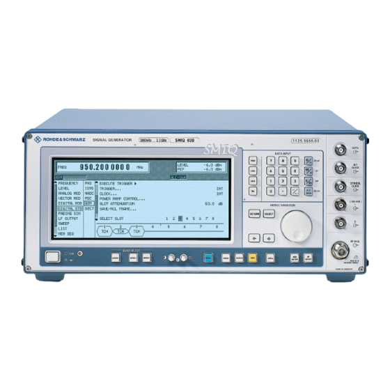
- Page 1 Test and Measurement Division Operating Manual VECTOR SIGNAL GENERATOR SMIQ02B 1125.5555.02 SMIQ03B 1125.5555.03 SMIQ03HD 1125.5555.33 SMIQ04B 1125.5555.04 SMIQ06B 1125.5555.06 SMIQ06ATE 1125.5555.26 Volume 1 This Operating Manual consists of 2 volumes Printed in the Federal Republic of Germany 1125.5610.12-11...
- Page 3 SMIQ06ATE Supplement Supplement to Manual SMIQ06ATE The functionality of model SMIQ06ATE and its compliance with specifications correspond to model SMIQ06B (see Data sheet SMIQB06B). Model SMIQ06ATE differs from model SMIQ06B as follows: • The instrument has no display (item 1 in front panel view) •...
- Page 5 SMIQ Supplement Supplement to Manual SMIQ Special Features of HD Model VECTOR MOD menu with model SMIQ03HD: IQ FILTER Selection between filter off and a 2.5 MHz, 5 MHz, 7.5 MHz or 10 MHz lowpass filter in the base- band. The filters suppress noise in the baseband, which improves adjacent channel power (ACP) with W-CDMA.
- Page 6 Supplement SMIQ Option SMIQB57 incorporates a filter tailored to the channel bandwidth of a 3GPP W-CDMA signal (3.84 MHz) for suppressing unwanted signal components outside the useful band. SMIQB57 can for this reason be used effectively only with this particular type of digital modulation.
- Page 7 SMIQ Supplement New Features on All Models DIGITAL MOD – FILTER menu: A new filter was added: (FILTER...) FILTER TYPE GAUSS LINEAR linearized Gaussian filter for GSM_EDGE (to GSM Specification 05.04, Change Request A010) IEC/IEEE-bus command: :SOUR:DM:FILT:TYPE LGA GAUSS LINEAR (old version) linearized Gaussian filter for GSM_EDGE (to GSM Specification older than 05.04)
- Page 8 Supplement SMIQ If ADD OCNS is set to ON, • channels 15 to 30 of base station 1 are automatically set as shown in the table above • the power of the OCNS component is adjusted automatically so that the powers of the OCNS channels and the powers of the non-OCNS channels of base station 1 add up to yield a sum power of linear 1.
- Page 9 Supplement to Manual SMIQ Output Mode NORMAL This mode corresponds to that of the previous SMIQ. LOW NOISE: The modulation in the SMIQ is set so that the power of the second and following adjacent channels (ALT1...) is minimal. LOW DIST: The modulation in the SMIQ is set so that the power of the first adjacent channel (ADJ) is minimal.
- Page 11 SMIQ Tabbed Divider Overview Tabbed Divider Overview Volume 1 How to Use this Manual Contents Data Sheet Supplement to Data Sheet Safety Instructions Certificate of quality EC Certificate of Conformity List of R & S Representatives Tabbed Divider Chapter 1: Preparation for Use Chapter 2: Manual Operation...
- Page 12 SMIQ as well as all specifications of the unit and available options. The following models and options are described in this manual: • SMIQ02B – Vector Signal Generator 300 kHz to 2.2 GHz • SMIQ03B – Vector Signal Generator 300 kHz to 3.3 GHz •...
- Page 13 SMIQ Introduction on how to use the manual Chapter 3 provides information on remote control of SMIQ. It informs about basics like IEC/IEEE bus, RS-232C interface, interface and device-dependent messages, command processing, status reporting system etc. It also includes an overview of each command system and describes all commands available in the unit and its options.
- Page 15 Before putting the product into operation for the first time, make sure to read the following S a f e t y I n s t r u c t i o n s Rohde & Schwarz makes every effort to keep the safety standard of its products up to date and to offer its customers the highest possible degree of safety.
- Page 16 Safety Instructions Observing the safety instructions will help prevent personal injury or damage of any kind caused by dangerous situations. Therefore, carefully read through and adhere to the following safety instructions before putting the product into operation. It is also absolutely essential to observe the additional safety instructions on personal safety that appear in other parts of the documentation.
- Page 17 Safety Instructions 4. If products/components are mechanically 10. Intentionally breaking the protective earth and/or thermically processed in a manner connection either in the feed line or in the that goes beyond their intended use, product itself is not permitted. Doing so can hazardous substances (heavy-metal dust result in the danger of an electric shock such as lead, beryllium, nickel) may be...
- Page 18 Safety Instructions 19. If a product is to be permanently installed, matching Rohde & Schwarz type (see the connection between the PE terminal on spare parts list). Batteries and storage site and the product's PE conductor must batteries are hazardous waste. Dispose of be made first before any other connection them only in specially marked containers.
- Page 19 Por favor lea imprescindiblemente antes de la primera puesta en funcionamiento las siguientes informaciones de seguridad Informaciones de seguridad Es el principio de Rohde & Schwarz de tener a sus productos siempre al día con los estandards de seguridad y de ofrecer a sus clientes el máximo grado de seguridad. Nuestros productos y todos los equipos adicionales son siempre fabricados y examinados según las normas de seguridad vigentes.
- Page 20 Informaciones de seguridad Tener en cuenta las informaciones de seguridad sirve para tratar de evitar daños y peligros de toda clase. Es necesario de que se lean las siguientes informaciones de seguridad concienzudamente y se tengan en cuenta debidamente antes de la puesta en funcionamiento del producto. También deberán ser tenidas en cuenta las informaciones para la protección de personas que encontrarán en otro capítulo de esta documentación y que también son obligatorias de seguir.
- Page 21 Informaciones de seguridad seguridad (control a primera vista, control de peligro a causa de la radiación conductor protector, medición de resistencia electromagnética. El empresario está de aislamiento, medición de medición de la comprometido a valorar y señalar areas de corriente conductora, control trabajo en las que se corra un riesgo de...
- Page 22 Informaciones de seguridad 12. No utilice nunca el producto si está dañado el 20. En caso de que los productos que son cable eléctrico. Asegure a través de las instalados fijamente en un lugar sean sin medidas de protección y de instalación protector implementado, autointerruptor o adecuadas de que el cable de eléctrico no similares objetos de protección, deberá...
- Page 23 Informaciones de seguridad 27. Baterías y acumuladores no deben de ser 31. Las asas instaladas en los productos sirven expuestos a temperaturas altas o al fuego. solamente de ayuda para el manejo que Guardar baterías y acumuladores fuera del solamente está previsto para personas. Por alcance de los niños.
-
Page 24: Table Of Contents
SMIQ Contents Contents 1 Preparation for Use ..................... 1.2 Putting into Operation......................1.2 1.1.1 Supply Voltage ......................1.2 1.1.2 Switching On/Off the Instrument ................1.2 1.1.3 Initial Status......................1.3 1.1.4 Setting Contrast and Brightness of the Display............1.3 1.1.5 RAM with Battery Back-Up..................1.3 1.1.6 Preset Setting...................... - Page 25 Contents SMIQ 2 Operation ......................2.1 Front and Rear Panel ......................2.1 2.1.1 Display........................2.1 2.1.2 Controls and Inputs/Outputs of the Front Panel............2.3 2.1.3 Elements of the Rear Panel ................... 2.13 Basic Operating Steps ......................2.22 2.2.1 Design of the Display ..................... 2.22 2.2.2 Calling the Menus....................
- Page 26 SMIQ Contents 2.7.3.2 Preemphasis ................... 2.62 2.7.4 Phase Modulation....................2.63 2.7.4.1 PM Deviation Limits ................2.64 2.7.5 Pulse Modulation....................2.65 Vector Modulation ....................... 2.66 2.8.1 I/Q Impairment ....................... 2.69 Fading Simulation ....................... 2.70 2.9.1 Output Power with Fading ..................2.71 2.9.2 Two-Channel Fading ....................
- Page 27 Contents SMIQ 2.12.4 Menu IS-95 CDMA Standard - Forward Link Signal..........2.136 2.12.5 Menu IS-95 CDMA Standard - Reverse Link Signal without Channel Coding ..2.146 2.12.6 Menu IS-95 CDMA Standard - Reverse Link Signal with Channel Coding ..2.148 2.13 Digital Standard W-CDMA (NTT DoCoMo/ARIB 0.0) ............
- Page 28 SMIQ Contents 2.15 Enhanced Functions For Digital Standard 3GPP W-CDMA (FDD) ........2.236 2.15.1 Test Setup ......................2.236 2.15.2 Branching to Menus SMIQB48 of Digital Standard 3GPP WCDMA ....2.237 2.15.3 Enhanced Channels BS1/MS1................2.238 2.15.3.1 Downlink ....................2.240 2.15.3.1.1 P-CCPCH/BCH with System Frame Number...... 2.241 2.15.3.1.2 Channel Coding..............
- Page 29 Contents SMIQ 2.21 Arbitrary Waveform Generator ARB ................2.341 2.21.1 Function........................ 2.341 2.19.1.1 Use of WinIQSIM .................. 2.344 2.21.2 ARB MOD Menu....................2.345 2.21.2.1 ARB MOD - TRIGGER Menu ............... 2.347 2.21.2.2 ARB MOD - SELECT WAVEFORM Menu ........... 2.349 2.21.2.3 ARB MOD - DELETE WAVEFORM Menu ...........
- Page 30 SMIQ Contents 2.29 Utilities..........................2.410 2.29.1 IEC-Bus Address (SYSTEM-GPIB)..............2.410 2.29.2 Parameter of the RS232 Interface (SYSTEM-RS232) ......... 2.411 2.29.3 Parameter of the SER DATA Input (SYSTEM-SERDATA) ........2.412 2.29.4 Suppressing Indications and Deleting Memories (SYSTEM-SECURITY) ... 2.413 2.29.5 Indication of the IEC-Bus Language (LANGUAGE) ..........2.414 2.29.6 Reference Frequency Internal/External (REF OSC) ..........
- Page 31 Contents SMIQ 3 Remote Control....................3.1 Brief Instructions........................3.1 3.1.1 IEC-Bus........................3.1 3.1.2 RS-232 Interface......................3.2 Switchover to Remote Control..................... 3.2 3.2.1 Remote Control via IEC Bus ..................3.3 3.2.1.1 Setting the Device Address............... 3.3 3.2.1.2 Indications during Remote Control ............3.3 3.2.1.3 Return to Manual Operation..............
- Page 32 SMIQ Contents 3.5.14.4 SOURce:DIST Subsystem..............3.61 3.5.14.5 SOURce:DM Subsystem ................ 3.65 Vector Modulation ................... 3.65 Digital Modulation ................... 3.67 3.5.14.6 SOURce:FM Subsystem................. 3.78 3.5.14.7 SOURce:FREQuency Subsystem ............3.80 3.5.14.8 SOURce:FSIM-Subsystem ..............3.82 3.5.14.9 SOURce:GPS Subsystem ..............3.93 3.5.14.10 SOURce:GSM Subsystem (Digital Standard GSM/EDGE) ....3.96 3.5.14.11 SOURce:IS95 Subsystem (Digital Standard IS-95 CDMA) ....
- Page 33 Contents SMIQ 3.7.4 Application of the Status Reporting Systems............3.225 3.7.4.1 Service Request, Making Use of the Hierarchy Structure ....3.225 3.7.4.2 Serial Poll....................3.225 3.7.4.3 Parallel Poll ................... 3.226 3.7.4.4 Query by Means of Commands ............3.226 3.7.4.5 Error Queue Query ................3.226 3.7.5 Resetting Values of the Status Reporting Systems ..........
- Page 34 SMIQ Contents 5 Checking the Rated Characteristics ..............5.2 Test Equipment and Test Assemblies................. 5.2 5.1.1 Measuring Equipment and Accessories..............5.2 5.1.2 Test Assemblies....................... 5.3 5.1.2.1 Standard Test Assembly for Analog Modulations ........5.3 5.1.2.2 Test Assembly for Analog Modulations with Audio Analyzer ....5.5 5.1.2.3 Test Assembly for Broadband FM ............
- Page 35 Contents SMIQ 5.3.9.2 AM Distortion ..................5.35 5.3.9.3 AM Frequency Response ............... 5.35 5.3.9.4 Residual PhiM with AM ................5.36 5.3.9.5 Level Monitoring at Input EXT1............... 5.36 5.3.10 Broadband Amplitude Modulation ................5.37 5.3.11 Pulse Modulation....................5.37 5.3.11.1 ON/OFF Ratio ..................5.37 5.3.11.2 Dynamic Characteristics .................
- Page 36 SMIQ Contents 5.3.20.2 3GPP W-CDMA with 8 Code Channels..........5.67 5.3.20.3 3GPP W-CDMA Test Model 1, 64 DPCH..........5.68 5.3.21 3GPP W-CDMA Enhanced Channels (SMIQB48) ..........5.69 5.3.21.1 External Power Control ................5.69 5.3.22 Bit Error Rate Test (Option SMIQB21)..............5.70 5.3.23 Fading Simulation (Option SMIQB14/SMIQB15) ...........
- Page 37 Contents SMIQ C Annex C ........................C.1 List of Commands (with SCPI Conformity Information) ............C.1 D Annex D ........................D.1 Programming Examples .......................D.1 Including IEC-Bus Library for QuickBasic ..............D.1 Initialization and Default Status ................D.1 2.1. Initiate Controller ......................D.1 2.2. Initiate Instrument.....................D.1 Transmission of Instrument Setting Commands............D.2 Switchover to Manual Control ..................D.2 Reading out Instrument Settings ................D.2 List Management......................D.3...
- Page 38 SMIQ Contents Tables Table 2-1 Input sockets for the different types of modulation............2.55 Table 2-2 Status messages in the case of a deviation from the rated value at the external modulation inputs EXT1 and EXT2..................... 2.56 Table 2-3 Parameter setting ranges ....................2.69 π...
- Page 39 Contents SMIQ Figures Fig. 1-1 SMIQ, view from the top ....................1.5 Fig. 1-2 Module FSIM....................... 1.9 Fig. 1-3 Module NDSIM......................1.13 Fig. 1-4 Module MCOD ......................1.14 Fig. 2-1 Front panel view......................2.2 Fig. 2-2 Rear panel view ......................2.12 Fig.
- Page 40 SMIQ Contents Fig. 2-46 Pulse on Oscilloscope ....................2.84 Fig. 2-47 Modulation coder in SMIQ ..................2.85 Fig. 2-48 Digital input signals of modulation coder ..............2.85 Fig. 2-49 Functional blocks Coding and Mapping..............2.86 Fig. 2-50 Constellation diagrams of BPSK, QPSK, 8PSK and 16QAM ........2.86 Fig.
- Page 41 Contents SMIQ Fig. 2-81 Menu DIGITAL STD - IS-95 - MODE - FWD_LINK_18, equipped with options modulation coder SMIQB20, data generator SMIQB11 and SMIQB42 ....2.135 Fig. 2-82 Menu DIGITAL STD - IS-95 - MODULATION..., equipped with options modulation coder SMIQB20, data generator SMIQB11 and SMIQB42 ....2.137 Fig.
- Page 42 SMIQ Contents Fig. 2-120 DIGITAL STD – WCDMA/3GPP – MS CONFIGURATION: DPCCH + DPDCH Mode menu......................2.200 Fig. 2-121 Dynamic change of channel power (continuous)............ 2.201 Fig. 2-122 DIGITAL STD – WCDMA/3GPP – BS CONFIGURATION / MULTI CHANNEL EDIT menu......................2.203 Fig.
- Page 43 Contents SMIQ Fig. 2-168 DIGITAL STD - WCDMA/3GPP - OCNS CHANNELS menu ......... 2.246 Fig. 2-169 DIGITAL STD - WCDMA/3GPP ADDITIONAL MS STATE menu......2.249 Fig. 2-170 Menu DIGITAL STD - NADC, SMIQ equipped with Modulation Coder SMIQB20 and Data Generator SMIQB11 ................2.255 Fig.
- Page 44 SMIQ Contents Fig. 2-197 Menu DIGITAL STD - GSM/EDGE - SELECT SLOT – ALL_DATA, SMIQ equipped with Modulation Coder SMIQB20 and Data Generator SMIQB11 ..2.304 Fig. 2-198 Menu DIGITAL STD - GSM/EDGE - SELECT SLOT – EDGE, SMIQ equipped with Modulation Coder SMIQB20 and Data Generator SMIQB11 ......
- Page 45 Contents SMIQ Fig. 2-244 Menu MEM SEQ -OPERATION-page (preset setting) ........... 2.385 Fig. 2-245 Menu MEM SEQ - EDIT page ................2.386 Fig. 2-246 Menu UTILITIES -SYSTEM -GPIB ................. 2.387 Fig. 2-247 Menu UTILITIES - SYSTEM - RS232..............2.388 Fig. 2-248 Menu UTILITIES - SYSTEM - SERDATA...............
- Page 46 Safety Instructions This unit has been designed and tested in accordance with the EC Certificate of Conformity and has left the manufacturer’s plant in a condition fully complying with safety standards. To maintain this condition and to ensure safe operation, the user must observe all instructions and warnings given in this operating manual.
- Page 47 Safety Instructions 10. Ensure that the connections with information 12. Equipment returned or sent in for repair must be technology equipment comply with IEC950 / packed in the original packing or in packing with EN60950. electrostatic and mechanical protection. 11. Lithium batteries must not be exposed to high Electrostatics via the connectors may dama- temperatures or fire.
- Page 48 EC Certificate of Conformity Certificate No.: 2002-23 This is to certify that: Equipment type Stock No. Designation SMIQ06ATE 1125.5555.26 Vector Signal Generator complies with the provisions of the Directive of the Council of the European Union on the approximation of the laws of the Member States - relating to electrical equipment for use within defined voltage limits (73/23/EEC revised by 93/68/EEC) - relating to electromagnetic compatibility...
- Page 50 EC Certificate of Conformity Certificate No.: 2002-09 This is to certify that: Equipment type Stock No. Designation SMIQ03HD 1125.5555.33 Vector Signal Generator complies with the provisions of the Directive of the Council of the European Union on the approximation of the laws of the Member States - relating to electrical equipment for use within defined voltage limits (73/23/EEC revised by 93/68/EEC) - relating to electromagnetic compatibility...
- Page 52 EC Certificate of Conformity Certificate No.: 99015 This is to certify that: Equipment type Order No. Designation SMIQ02B 1125.5555.02 Vector Signal Generator SMIQ03B 1125.5555.03 SMIQ04B 1125.5555.04 SMIQ06B 1125.5555.06 SMIQB10 1085.5009.02 Modulation Coder SMIQB11 1085.4502.02/.04 Data Generator SMIQB12 1085.2800.02/.04 Memory Extension SMIQB14 1085.4002.02...
-
Page 54: Preparation For Use
SMIQ Putting into Operation Preparation for Use Putting into Operation Before putting the SMIQ into operation, please make sure that • the covers of the casing are put on and screwed, • the ventilation openings are free, • no signal voltage levels exceeding the permissible limits are applied at the inputs, •... -
Page 55: Initial Status
Putting into Operation SMIQ 1.1.3 Initial Status Upon switching on, the instrument either automatically assumes the status which was set when it was switched off (parameter POWER-ON STATE PREVIOUS SETTING in LEVEL-LEVEL menu) or the RF output is disconnected (POWER-ON STATE RF OFF). If the instrument need not to be operated from the initial status any further, a defined default status should be established by pressing the [PRESET] key prior to further settings. -
Page 56: Preset Setting
SMIQ Functional Test 1.1.6 Preset Setting A defined setting status is achieved by pressing the [PRESET] key. Preset Status: RF frequency 100 MHz RF level -30 dBm Reference frequency internal, adjustment off Offsets Modulations switched off Transient-free level setting switched off, level attenuator mode: AUTO Internal level control level ALC: AUTO User correction... -
Page 57: Fitting The Options
Fitting the Options SMIQ Fitting the Options Due to its variety of options, the SMIQ offers the possibility of providing the instrument with the equipment exactly corresponding to the application. Newly fitted options are automatically recognized and the relevant parameters added in the menu. After every change of the instrument configuration, the CMOS RAM has to be cleared as the storage data shift: ½... -
Page 58: Overview Of The Slots
SMIQ Fitting the Options 1.3.2 Overview of the Slots POWS1 Option SM-B1 ATTC FRO = front unit MCOD = modulation coder FMOD = FM/PM modulator DGEN = data generator IQMOD = I/Q modulator FSIM = fading simulator IQCON = I/Q converter POWS1 = power supply SUM = summing loop ATTC = attenuator... -
Page 59: Option Sm-B5 - Fm/Pm Modulator
Fitting the Options SMIQ The crystal oscillator was factory-tuned to nominal frequency and the Set tuning voltage and appropriate tuning voltage indicated on the cover of the module. The calibrate OCXO calibration value now has to be calculated from this value and transferred to the memory of the signal generator. -
Page 60: Option Smiqb11 - Data Generator
SMIQ Fitting the Options 1.3.5 Option SMIQB11 - Data Generator The Data Generator is fitted at the slot with label "DGEN". ½ Plug the module into the slot. ½ Lock it and fasten all screws. ½ Plug W341 onto X341. ½... -
Page 61: Option Smiqb14 - Fading Simulator Fsim1
Fitting the Options SMIQ 1.3.7 Option SMIQB14 - Fading Simulator FSIM1 The Fading Simulator is fitted at the slot with label ’FSIM1’. Before fitting the option SMIQB14 (FSIM1) first check the correct settings of the jumpers on the module. For FSIM modules of series 1085.XXXX (see screening cover) the jumper setting also depends on the number of fading simulators installed, either one (FSIM1) or two (FSIM1 and FSIM2). -
Page 62: Fig. 1-2 Module Fsim
SMIQ Fitting the Options ½ Plug the module into the appropriate slot, lock it and fasten all Fitting the option screws. ½ Open the air inlets at the housing frame by breaking out the safety glass plate which belongs to the option. ½... -
Page 63: Option Smiqb15 - Second Fading Simulator (Fsim2)
Fitting the Options SMIQ 1.3.8 Option SMIQB15 - Second Fading Simulator (FSIM2) The second Fading Simulator is fitted at the slot with label ’FSIM2’. Before fitting the option SMIQB15 (FSIM2) please check the correct settings of the jumpers on both fading modules FSIM1 (see Section 1.3.7) and FSIM2. - Page 64 SMIQ Fitting the Options ½ Plug the module into the appropriate slot for the FSIM2, lock it and Fitting the option fasten all screws. ½ Open the air inlets at the housing frame by breaking out the safety glass plate which belongs to the option. ½...
-
Page 65: Option Smiqb17 - Noise Generator And Distortion Simulator
Fitting the Options SMIQ 1.3.9 Option SMIQB17 - Noise Generator and Distortion Simulator Depending on which options are fitted, the NDSIM module is mounted in the slot labelled FSIM1/FMOD/NDSIM or FSIM2/FMOD/NDSIM or E6GHZ/FMOD/NDSIM (in older units slot FSIM1/FMOD or FSIM2/FMOD). After an instrument warm-up period of 1 hour, the NDSIM as well as the IQ Modulator should be calibrated. -
Page 66: Option Smiqb20 - Modulation Coder
SMIQ Fitting the Options X600 NDSIM X606 X605 X604 X603 X607 X602 X601 Fig. 1-3 Module NDSIM Connector X607 is unused and provided only in some modules. ½ The included adhesive label ’Option included’ is to be fixed at the rear panel of the SMIQ. -
Page 67: Option Smiqb21 - Bit Error Rate Test
Fitting the Options SMIQ X320 MCOD X330 X329 X328 X327 X326 X325 X324 X323 X322 X321 Fig. 1-4 Module MCOD ½ The included adhesive label "Option included" is to be fixed at the rear panel of the SMIQ. 1.3.11 Option SMIQB21 - Bit Error Rate Test Software option SMIQB21 has to be enabled by entering a key upon installation. -
Page 68: Other Software Options
SMIQ Fitting the Options Connector The clock and data signals output by the DUT must have TTL level and are connected to the BER (bit error rate) input, a 9-contact SUB-D connector at the rear of the unit labelled BER. Pin assignment is as follows: SUB-D connector Adapter cable Order No. -
Page 69: Option Smiqb19 - Rear Panel Connections For Rf And Lf
Mounting into a 19" Rack SMIQ ½ Switch on SMIQ. Enabling option: ½ Call up menu UTILITIES. (Select it by means of the rollkey, confirm with [SELECT] key). ½ Call up menu INSTALL ==> [SELECT] ½ Call up menu OPTION TO INSTALL ==> [SELECT] ½... -
Page 70: Operation
SMIQ Front Panel Operation Front and Rear Panel 2.1.1 Display (cf. Fig. 2-1, Front panel view) 100. 000 000 0 - 30.0 FREQ LEVEL FREQUENCY FM1 DEVIATION 1.00 LEVEL BB-AM FM1 SOURCE EXT1 EXT2 ANALOG MOD LFGEN FREQ 1.000 0 VECTOR MOD DIGITAL MOD FM2 DEVIATION... -
Page 71: Fig. 2-1 Front Panel View
Front Panel SMIQ Fig. 2-1 Front panel view 1125.5555.03... -
Page 72: Controls And Inputs/Outputs Of The Front Panel
SMIQ Front Panel 2.1.2 Controls and Inputs/Outputs of the Front Panel (cf. Fig. 2-1, front panel view) DATA INPUT Parameter field Parameters RF frequency and RF level can be entered see as well FR EQ directly by means of the parameter keys, alternatively Chapter 2 to menu operation. - Page 73 Front Panel SMIQ Fig. 2-1 Front panel view 1125.5555.03...
- Page 74 SMIQ Front Panel DATA INPUT Unit keys with enter function The unit keys terminate the input of values and specify see as well the multiplication factor for the respective basic unit. Chapter 2 dBµV The basic units are displayed next to the input field Section while numbers are entered.
- Page 75 Front Panel SMIQ Fig. 2-1 Front panel view 1125.5555.03...
- Page 76 SMIQ Front Panel MENU/VARIATION Rotary knob The rotary knob moves the menu cursor over the See as well positions of a menu level to choose from or varies the Chapter 2 value of a parameter. The variation is either effected in Section "Basic steps of one or in a step width that can be specified at will.
- Page 77 Front Panel SMIQ Fig. 2-1 Front panel view 1125.5555.03...
- Page 78 SMIQ Front Panel Input external modulation signal for I/Q Section modulation. "Vector Modulation" Output* Q-signal with operating mode internal. Input/output resistance 50 Ω. Nominal voltage: U s = 0.5 V max. permissible overvoltage: ± 5V Output RF signal. Section "Use of RF 50 Source resistance 50 Ω...
- Page 79 Front Panel SMIQ Fig. 2-1 Front panel view 1125.5555.03 2.10...
- Page 80 SMIQ Front Panel Brightness and contrast of the display can be set using See as well the rotary knobs. Chapter 1 Section "Setting of Contrast Contrast and Bright- ness of the Display" Brightness QUICK SELECT QUICK SELECT ASSI G N MENU1 MENU2 See as well...
-
Page 81: Fig. 2-2 Rear Panel View
Rear Panel SMIQ Fig. 2-2 Rear panel view 1125.5555.03 2.12... -
Page 82: Elements Of The Rear Panel
SMIQ Rear Panel 2.1.3 Elements of the Rear Panel (Cf. Fig. 2-2, Rear panel view) I FADED Faded I signal. see as well I FADED Chapter 2, "Fading Simulation" Q FADED Faded Q signal Q FADED IQ AUX Output I/Q modulated subcarrier. I/Q AUX Frequency 300 MHz, level -5 dBm, source resistance 50Ω... - Page 83 Rear Panel SMIQ Fig. 2-2 Rear panel view 1125.5555.03 2.14...
- Page 84 SMIQ Rear Panel PAR DATA Description 8 - ⊥ Ground 9 - LEV-ATT Signal input/output for controlling of level reduction. Output: TTL signal. Input: Input resistance 1kΩ or 50Ω. Trigger threshold can be set from -2.5 to 2.5V, max. ± 15V, max. 40 mA 10 - ⊥...
- Page 85 Rear Panel SMIQ Fig. 2-2 Rear panel view 1125.5555.03 2.16...
- Page 86 SMIQ Rear Panel DATA Cut-out, provided to relocate the DATA DATA input/output at the front to the rear of the instrument. BIT CLK Cut-out, provided to relocate the BIT CLK BIT CLK input/output at the front to the rear of the instrument.
- Page 87 Rear Panel SMIQ Fig. 2-2 Rear panel view 1125.5555.03 2.18...
- Page 88 SMIQ Rear Panel Interface for BER Test See as well chapter 2, section "External Modu- lation Source AMIQ" and "Bit Error Rate Test" RS-232 RS-232 interface, see as well RS 232 used for software update, the loading of Chapter 3 calibration data, and remote control.
- Page 89 Rear Panel SMIQ Fig. 2-2 Rear panel view 1125.5555.03 2.20...
- Page 90 SMIQ Rear Panel Cut-out, provided to relocate the RF output at the front to the rear of the instrument Output LF signal of the internal LF generator. Source resistance < 10 Ω. EXT1 Input external modulation signal, EXT 1 alternatively for AM or FM (PM). Input resistance >100 kΩ.
-
Page 91: Basic Operating Steps
Basic Operating Steps SMIQ Basic Operating Steps The operating principle is explained in this section. For better understanding, please read section "Sample Setting for First Users" (Section 2.2.10) in addition. To operate the instrument, menus are called in the display. All setting possibilities and the current setting status are evident from the menus. -
Page 92: Calling The Menus
SMIQ Basic Operating Steps (3)The indication fields below the header field are reserved for the menu representations. Menu fields The image contents of these fields change as a function of the menu selected. The field at the left-hand display margin is occupied with the main menu, the topmost level of the menu structure. -
Page 93: Selection And Change Of Parameters
Basic Operating Steps SMIQ 2.2.3 Selection and Change of Parameters Ø Set the menu cursor to the name of the parameter desired using the rotary Select parameter knob, e.g. to AM DEPTH in the AM menu, Fig. 2.4. Ø Via value input or using rotary knob. Change setting value Ø... -
Page 94: Triggering Action
SMIQ Basic Operating Steps Quick selection of The quick selection of a parameter reduces the number of operating steps if a parameter several parameters are set successively. The menu cursor can directly be set further from line to line in the column of the setting values by pressing the [SELECT] key. -
Page 95: Use Of [Freq] And [Level] Keys
Basic Operating Steps SMIQ 2.2.6 Use of [FREQ] and [LEVEL] Keys RF frequency and RF level can be set without menu operation as well using direct keys [FREQ] and [LEVEL]. The input value considers the offset, see Sections 2.4 and 2.5. Ø... -
Page 96: Correction Of Input
SMIQ Sample Setting for First Users 2.2.10 Correction of Input Digital entries can be corrected by one of the following keys before terminating the input: ç ç ] ç ç The backspace key deletes the value entered digit by digit. When the last Key [-/ digit is deleted, the previous value is displayed. - Page 97 Sample Setting for First Users SMIQ The output signal is to be amplitude-modulated next. - AM modulation depth 15.5 % - Modulation frequency 3 kHz Operating steps Explanations MENU / VARIATION MENU / VARIATION Select ANALOG MOD menu. Ø Set menu cursor to ANALOG MOD using the rotary knob and SELECT ANALOG MOD...
-
Page 98: Fig. 2-5 Display After Am Setting
SMIQ Sample Setting for First Users Operating steps Explanations MENU / VARIATION Select INT 1 as internal modulation MENU / VARIATION source. The selection mark marks INT. AM is SELECT . INT faded in the status line as a hint that AM is switched on. - Page 99 Sample Setting for First Users SMIQ Subsequently to the above setting, 420 MHz as new RF frequency and 12.5 kHz as the step width for the RF frequency variation are set in the following. Parameter quick select is used, which reduces the number of operating steps.
- Page 100 SMIQ Sample Setting for First Users Operating steps Explanations MENU / VARIATION Set menu cursor to parameter KNOB STEP. KNOB STEP Set menu cursor to the current KNOB SELECT STEP selection. MENU / VARIATION Select USER (user-defined step MENU / VARIATION width).
-
Page 101: List Editor
List Editor SMIQ 2.2.12 List Editor The SMIQ offers the possibility to generate lists. Lists are used for setting sequences LIST mode or (memory sequence), as data source for digital modulations or for level correction which can be defined by the user (UCOR). They consist of elements which are defined by an index and at least one parameter per index. -
Page 102: Select And Generate - Select List
SMIQ List Editor Opens a selection window in which the list to be deleted can be selected. DELETE LIST Selection of the edit function for processing the lists. The EDIT page is FUNCTION automatically called through the selection (cf. Section 2.2.11.3). FILL Filling a list with elements. -
Page 103: Deletion Of Lists - Delete List
List Editor SMIQ Generating a new list. The name of the list cannot be selected freely in the CREATE NEW LIST case of manual control. A definite list name is automatically generated in the following form: MSEQ<n>, with <n> ∈ {0..9}, e.g. MSEQ1 (with Memory Sequence) This applies correspondingly to the other operating modes. -
Page 104: Edition Of Lists
SMIQ List Editor 2.2.11.3 Edition of Lists Due to the selection of an edit mode on the OPERATION page the EDIT page is automatically activated. When the EDIT/VIEW function is selected, the largest possible section of the list is displayed (cf. Fig. 2-10). - Page 105 List Editor SMIQ Ø Mark the index associated to the parameter using the rotary knob or directly Select parameters enter the value of the index via the numeric keys. Ø Press [SELECT] key. Parameter MEMORY is marked. If the second parameter DWELL is to be marked, press the [SELECT] key again.
- Page 106 SMIQ List Editor Setting the filling range. FILL AT Lower limit (index) RANGE Number of the elements to be inserted PARAMETER Selection on which of the parameters the filling function is to have an effect. This menu option is eliminated if the list only includes elements with one parameter.
- Page 107 List Editor SMIQ Block function INSERT Function INSERT inserts the desired number of elements with constant or linearly increasing/decreasing values before the element with the given starting index. All elements which had been stored from the starting index are shifted to the end of the range to be inserted. Input is effected analogously to filling a list.
-
Page 108: Pattern Setting To Operate The List Editor
SMIQ List Editor Block function DELETE Function DELETE deletes the elements of the range indicated. This does not leave a gap in the list but the remaining elements move forward. If the given range exceeds the end of the list, deletion until the end of the list is effected. - Page 109 List Editor SMIQ At the beginning of the operation sequence, menu MEM SEQ is called. First a list MSEQ0 has to be generated and then activated. The menu cursor marks a parameter of the setting menu on the OPERATION page (c.f. Fig. 2-14). - 30.0 100.
- Page 110 SMIQ List Editor Operating steps Explanations MENU / VARIATION Select single-value function MENU / VARIATION EDIT/VIEW. The EDIT page of the MEM SEQ menu is called. The menu cursor .EDIT VIEW. SELECT marks the index of the first element of list MSEQ0. Set the menu cursor to the memory SELECT location number value of the first...
- Page 111 List Editor SMIQ - 30.0 100. 000 000 0 LEVE L FREQ FREQUENCY SELECT LIST... CURRENT: MSEQ0 FILL INSERT DELETE EDIT/VIEW LEVEL FUNCTION ANALOG MOD -INDEX - FREE 0246 - LEN 0010 MEMORY DWELL VECTOR MOD 0001 DIGITAL MOD DIGITAL STD LF OUTPUT SWEEP LIST...
-
Page 112: Save/Recall - Storing/Calling Of Instrument Settings
SMIQ Save/Recall 2.2.12 Save/Recall - Storing/Calling of Instrument Settings 50 complete instrument settings can be stored in memory locations 1 to 50. Operating steps Explanations DATA INPUT Store current instrument setting in memory location 12. SAVE ENTER DATA INPUT Call instrument setting of memory location 12. -
Page 113: Menu Summary
Menu Summary SMIQ Menu Summary FREQUENCY LEVEL LEVEL UCOR ANALOG MOD BB-AM ( option SM-B5) ( option SM-B5) VECTOR MOD (can be equipped with option SMIQB47) (options SMIQB20, SMIQB11 and SMIQB12) DIGITAL MOD DIGITAL STD (options SMIQB20, SMIQB11, SMIQB12 and digital standards incl. -
Page 114: Rf Frequency
SMIQ RF Frequency RF Frequency The RF frequency can be set directly using the [FREQ] key (cf. Section 2.2.6) or by accessing menu FREQUENCY. The frequency of the RF output signal is entered/indicated under FREQUENCY in the FREQUENCY menu. The input value of frequency settings opened by means of the [FREQ] key and indicated in the header line considers the offset in calculation (cf. -
Page 115: Frequency Offset
RF Frequency SMIQ The saved frequency is also loaded when instrument settings are EXCLUDE FROM RCL loaded with the [RCL] key or with a memory sequence. IEC/IEEE-bus command SOUR:FREQ:RCL INCL The RF frequency is not loaded when instrument settings are loaded, the current frequency is maintained. -
Page 116: Rf Level
SMIQ RF Level RF Level The RF level can be set directly using the [LEVEL] key (cf. Section 2.2.6) or by accessing the LEVEL menu. In the LEVEL-LEVEL menu, the set RF output level is indicated under AMPLITUDE. A two-line level display appears for digital modulation or digital standard. - Page 117 RF Level SMIQ OFFSET Input value of the level offset of the RF output level compared to the input value of the RF level indicated in the LEVEL header field. Input in dB (cf. Section 2.5.1, Level Offset). The status line indicates LEV-OFFST. IEC/IEEE-bus command SOUR:POW:OFFS 0 Input value of level limitation.
-
Page 118: Level Offset
SMIQ RF Level EXCLUDE FROM RCL OFF The saved RF level is also loaded when instrument settings are loaded with the [RCL] key or with a memory sequence. IEC/IEEE-bus command SOUR:POW:RCL INCL The RF level is not loaded when instrument settings are loaded, the current level is maintained. -
Page 119: Interrupt-Free Level Setting
RF Level SMIQ 2.5.2 Interrupt-free Level Setting In the ATTENUATOR MODE FIXED and ATTENUATOR MODE ELECTRONIC operating modes, level settings are carried out without interruption. The attenuator is switched electronically rather than mechanically. The MODE FIXED variation range is somewhat over 20 dB, the variation range of MODE ELECTRONIC over 90 dB. -
Page 120: Fig. 2-20 Menu Level - Alc (Preset Setting)
SMIQ RF Level Menu selection: LEVEL - ALC 100. 000 000 0 - 30.0 FREQ LEVEL ALC-ON LEVEL AUTO FREQUENCY STATE SAMPLE&HOLD TABLE LEVEL ALC OFF MODE UCOR ANALOG MOD SEARCH ONCE VECTOR MOD LEARN TABLE DIGITAL MOD DIGITAL STD LF OUTPUT SWEEP LIST... -
Page 121: User Correction (Ucor)
RF Level SMIQ 2.5.4 User Correction (UCOR) Function "User Correction" can be used to create and activate lists in which arbitrary RF frequencies are assigned level correction values. Up to 10 lists with a total of 160 correction values can be compiled. For frequencies which are not included in the list the level correction is determined by means of interpolation of the nearest correction values. -
Page 122: Emf
SMIQ RF Level Menu selection: LEVEL - UCOR - 27.0 LEVEL 100. 000 000 0 FREQ + 1 .9 UCOR LEVEL FREQUENCY SELECT LIST... CURRENT: UCOR1 LEVEL FUNCTION FILL INSERT DELETE EDIT/VIEW UCOR ANALOG MOD INDEX - FREE 70 - LEN 10 FREQUENCY UCOR1 VECTOR MOD... -
Page 123: Rf On / Off]-Key
RF Level SMIQ 2.5.6 [RF ON / OFF]-Key The RF output signal is switched on and off again using the [RF ON / OFF] key. This does not influence the current menu. When the output signal is switched off, the message "RF OFF" is displayed in the LEVEL indication of the header field. -
Page 124: Modulation - General
SMIQ Modulation - General Modulation - General The SMIQ offers the following modulations and digital standards: • Analog modulations - Amplitude modulation (AM) - Broadband AM (BB-AM) - Frequency modulation (FM; with option SM-B5 only) - Phase modulation (PM; with option SM-B5 only) - Pulse modulation (PULSE) •... -
Page 125: Table 2-2 Status Messages In The Case Of A Deviation From The Rated Value At The External Modulation Inputs Ext1 And Ext2
Modulation - General SMIQ EXT1/EXT2-Inputs The external modulation signal for AM, FM and PM at inputs EXT1 and EXT2 must show a voltage of = 1 V (V = 0.707 V) in order to maintain the modulation depth or deviation indicated. A monitoring circuit checks the input voltage in the frequency range 10 Hz to 100 kHz. -
Page 126: Lf Generator
SMIQ Modulation - General 2.6.2 LF Generator The SMIQ is equipped with a LF-generator as internal modulation source as a standard. The generator supplies sinusoidal signals in the frequency range from 0.1 Hz to kHz. The frequency settings of the internal modulation signals can be made in one of the modulation menus (AM, FM, PM) as well as in the LF-output menu. -
Page 127: Mod On/Off] Key
Modulation - General SMIQ 2.6.4 [MOD ON/OFF] Key The modulations can directly be switched on/off using the key or by accessing the modulation menus. When switching on using the [MOD ON/OFF] key, the modulation sources which are set in the modulation menus are used. -
Page 128: Analog Modulations
SMIQ Analog Modulations Analog Modulations 2.7.1 Amplitude Modulation Menu ANALOG MOD-AM offers access to settings for amplitude modulation. Notes: - The specifications for AM are only valid for the specified Level (PEP) range. - For AM, setting LEVEL-ALC-STATE ON or AUTO is recommended. Menu selection: ANALOG MOD - AM 100. -
Page 129: Broadband Am (Bb-Am)
Analog Modulations SMIQ 2.7.2 Broadband AM (BB-AM) In the BB-AM mode the I/Q modulator is used for amplitude modulation. Level control should be set to AUTO or ON (see section, Switching On/Off Internal Level Control). The modulation input (BB-AM) is identical with the I input of the I/Q modulator. The input impedance is 50 Ω. -
Page 130: Frequency Modulation
SMIQ Analog Modulations 2.7.3 Frequency Modulation Menu ANALOG MOD-FM offers access to settings for frequency modulation. Note: The FM and PM modulations cannot be set simultaneously and deactivate one another: Menu selection: ANALOG MOD-FM 100. 000 000 0 - 30.0 LEVEL FREQ FM1 DEVIATION... -
Page 131: Fm Deviation Limits
Analog Modulations SMIQ 2.7.3.1 FM Deviation Limits The maximal deviation depends on the RF frequency set (cf. Fig. 2-29). It is possible to enter a deviation that is too high for a certain RF frequency or to vary the RF frequency to a range in which the deviation can no longer be set. -
Page 132: Phase Modulation
SMIQ Analog Modulations 2.7.4 Phase Modulation Menu ANALOG MOD-PM offers access to settings for phase modulation. Note: The PM and FM modulations cannot be set simultaneously and deactivate one another. Menu selection: ANALOG MOD - PM 100. 000 000 0 - 30.0 LEVEL FREQ... -
Page 133: Pm Deviation Limits
Analog Modulations SMIQ 2.7.4.1 PM Deviation Limits The maximal deviation depends on the RF frequency set (cf. Fig. 2-31). It is possible to enter a deviation that is too high for a certain RF frequency or to vary the RF frequency to a range in which the deviation can no longer be set. -
Page 134: Pulse Modulation
SMIQ Analog Modulations 2.7.5 Pulse Modulation The pulse modulator can be controlled by an external source at the PULSE input. The polarity of the pulse modulation is selectable. With POLARITY = NORM, the RF level is on with HIGH level at modulation input PULSE. Menu MODULATION-PULSE offers access to settings for pulse modulation Menu selection: MODULATION - PULSE... -
Page 135: Vector Modulation
Vector Modulation SMIQ Vector Modulation In the vector modulation mode (I/Q modulation) external modulation signals can be applied to modulation inputs I and Q for a complex modulation of the RF carrier. I = 0.3 V SMIQ Q = 0.4 V ï... - Page 136 SMIQ Vector Modulation Menu selection: VECTOR MOD Fig. 2-34 VECTOR MOD menu (preset settings), equipped with option SMIQB47 and IQMOD var. 8 or higher Switches the vector modulation on and off. STATE IEC/IEEE-bus command SOUR:DM:IQ:STAT ON Switches the POW RAMP input for analog level control on and off. Thus an POWER RAMP external control signal can be used for carrier envelope modulation in parallel CONTROL...
- Page 137 Vector Modulation SMIQ Only available with option SMIQB47. IQ FILTER Selection between no filter and a 850 kHz, a 2.5 MHz or a 5 MHz lowpass in the baseband. A filter of these types suppresses noise in the baseband above 900 kHz, 3 MHz or 6 MHz, which improves ACP (Adjacent Channel Power) for IS95 and W-CDMA.
-
Page 138: I/Q Impairment
SMIQ Vector Modulation 2.8.1 I/Q Impairment For simulating an impairment of the vector modulation, a residual carrier (LEAKAGE), imbalanced I and Q modulation (IMBALANCE) and a quadrature offset can be entered. The input values for LEAKAGE and IMBALANCE are with reference to the voltage. Table 2-3 Parameter setting ranges Parameter... -
Page 139: Fading Simulation
Fading Simulation SMIQ Fading Simulation By means of the option Fading Simulator SMIQB14, multipath fading signals with 6 independent transmission paths can be generated. Important: The Fading Simulator can only be operated with the complex baseband signals I and Q. Therefore, it is necessary to switch on either Vector Modulation or Digital Modulation. -
Page 140: Output Power With Fading
SMIQ Fading Simulation 2.9.1 Output Power with Fading With a PATH LOSS setting of 0 dB, a single path of the fading simulator introduces an insertion loss between 12 dB and 18 dB for the IQ signals applied (with Insertion Loss Setting Mode = NORMAL). This insertion loss provides a headroom if several paths are superimposed on one another and also for the statistical influences to which a path is exposed. -
Page 141: Correlation Between Paths
Fading Simulation SMIQ 2.9.3 Correlation between Paths Fading processes of different paths normally do not depend on statistical processes. However, it is possible to set a correlation of paths 1 to 6 with paths 7 to 12 in pairs. To set the correlation, a synchronous signal processing is required for the two fading options which involves the following restrictions: •... -
Page 142: Menu Standard Fading
SMIQ Fading Simulation 2.9.4.1 Menu STANDARD FADING The settings for fading simulation can be accessed via the FADING SIM menu. Menu selection: FADING SIM Fig. 2-39 Menu STANDARD FADING (two Fading Simulators installed) Switching on fading simulation by selection of the number of active paths and CONFIGURATION channels. - Page 143 Fading Simulation SMIQ Opens a window for selecting a standard setting of the fading paths. The STANDARD parameter settings comply with the measurement specifications of mobile communication standards (e.g. GSM, CDMA, NADC). With standards TETRA TYPICAL URBAN and TETRA HILLY TERRAIN, all 6 paths are used with these parameters instead of the stipulated 2 paths.
- Page 144 SMIQ Fading Simulation The following parameter have to be set separately for each path. PATH Switching on and off a path. If the cursor is placed onto a path in the diagram, STATE it may be switched on and off by pressing one of the unit keys (toggle function).
- Page 145 Fading Simulation SMIQ Input value of the ratio of the actual Doppler Frequency shift to the Doppler FREQ RATIO Frequency setting with Ricean fading or Pure Doppler switched on. The actual Doppler Frequency shift depends on the simulated angle of incidence of the discrete component.
- Page 146 SMIQ Fading Simulation Switching on or off (NONE) a correlation with the selected path. This setting is CORR PATH accessible if both fading options SMIQB14 and SMIQB15 have been installed. Only a two by two correlation of paths 1 to 6 with paths 7 to 12 can be set. IEC/IEEE-bus command :SOUR:FSIM:PATH6:CORR:PATH 12 Input value of the amplitude of the complex correlation coefficient.
-
Page 147: Menu Fine Delay
Fading Simulation SMIQ 2.9.4.2 Menu FINE DELAY With the FINE DELAY mode a better time delay resolution of the paths is obtained. Two paths are possible for each option (SMIQB14 / SMIQB15). The system bandwidth of these paths is limited to 4.6 MHz, which is sufficient for 3GPP with 3.84 Msymb/s. - Page 148 SMIQ Fading Simulation 3GPP_BS_4.1.0_CASE4: SPEED: 250 km/h Pfad 1: DELAY 25 ns PATH LOSS 0 dB Pfad 2: DELAY 285ns PATH LOSS 3 dB Pfad 3: DELAY 546 ns PATH LOSS 6 dB Pfad 4: DELAY 806 ns PATH LOSS 9 dB 3GPP_UE_4.1.0_CASE1: SPEED:...
- Page 149 Fading Simulation SMIQ IEC/IEEE-bus command :SOUR:FSIM:FDEL:STAN G3C1 IEC/IEEE-bus command :SOUR:FSIM:FDEL:STAN G3UECn ( n=1...6) Notes: - The path delays correspond to those in 3GPP, TS 25.101 V4.1.0 (2001-06) und TS 25.141 V4.1.0 (2001-06). However, they include a basic delay of 25 ns of the Fading Simulator.
-
Page 150: Menu Moving Delay
SMIQ Fading Simulation 2.9.4.3 Menu MOVING DELAY In the MOVING DELAY mode, the Fading Simulator simulates the dynamic propagation conditions according to test case 3GPP, 25.104-320, Annex B3. 2 paths are simulated; the delay of path 1 remains unchanged, the delay of path 2 slowly moves to and fro sinusoidally. - Page 151 Fading Simulation SMIQ Sets the default setting of the path parameters. SET DEFAULT IEC/IEEE-bus command :SOUR:FSIM:MDEL:DEF Indicates the paths for subsequent parameters. These parameters can be set PATH individually for each path. Entry value of attenuation in path for the reference. PATH LOSS Value range: 0.0 to 50.0 dB.
-
Page 152: Menu Birth-Death
SMIQ Fading Simulation 2.9.4.4 Menu BIRTH-DEATH In the BIRTH-DEATH mode the Fading Simulator simulates the dynamic propagation conditions according to test case 3GPP, 25.104-320, Annex B4. To do this, 2 paths are simulated which alternately appear (BIRTH) or disappear (DEATH) at random time positions. - Page 153 Fading Simulation SMIQ Selection of a setting mode for the insertion loss of the fading simulator. INSERTION LOSS See explanation under STANDARD FADING. SETTING MODE IEC/IEEE-bus command :SOUR:FSIM:BIRT:ILOS:MODE NORM :SOUR:FSIM:BIRT:ILOS:MODE LACP Sets the default setting of the path parameters. SET DEFAULT IEC/IEEE-bus command :SOUR:FSIM:BIRT:DEF Indicates the paths for subsequent parameters.
-
Page 154: Test Procedure
SMIQ Fading Simulation 2.9.5 Test procedure The following settings can be used to demonstrate how Option SMIQB49 functions: Settings on SMIQ General Frequency 30 MHz Level -10 dB Digital Modulation (DIGITAL MOD) STATE SOURCE Data List LIST 1000 0000 0000 0000 0000 0000 0000 0000 (32 bits) MODULATION SYMBOL RATE 1 000 000 sym/s... -
Page 155: Digital Modulation
Digital Modulation SMIQ 2.10 Digital Modulation With option Modulation Coder (MCOD) SMIQB20 provided, SMIQ can generate digitally modulated output signals. Available modulation methods are ASK (amplitude shift keying), FSK (frequency shift keying), PSK (phase shift keying) as well as QAM (quadrature amplitude modulation). Baseband filtering and symbol rate can be freely set in a wide range. -
Page 156: Digital Modulation Methods And Coding
SMIQ Digital Modulation 2.10.1 Digital Modulation Methods and Coding The input sequence of modulation symbols d can be subject to different types of coding. I and Q values are assigned to the coded modulation symbols dc in the functional block MAPPING. I, ∆... -
Page 157: Modulation Π/4Dqpsk
Digital Modulation SMIQ For offset QPSK (OQPSK), the Q signal is delayed by half the symbol period with reference to the I signal. QAM modulation methods 16QAM, 32QAM, 64QAM and 256QAM were implemented according to ETSI standard ETS 300429 for Digital Video Broadcasting (DVB). All PSK and QAM modulation methods can be combined with COS and SQR_COS baseband filters as well as with IS-95 filters. -
Page 158: Fsk Modulation
SMIQ Digital Modulation 2.10.1.3 FSK Modulation For FSK modulation, frequency shifts are assigned to the modulation symbols. The modulation index h of this digital frequency modulation is determined by = ⋅ 2 ∆ / Symb The symbol rate f can be freely set to a maximum of 2.5 Msymb/s for all FSK modulations. With SYMB ∆f GMSK selected, the frequency deviation... -
Page 159: Table 2-9 Coding Algorithms
Digital Modulation SMIQ Table 2-9 Coding algorithms CODING Coding algorithm Applicable for K bit/symbol NONE K = 1 to 8 DIFF = (d + dc ) modulo 2k K = 1 to 7 GRAY+DIFF Gray coding with additional differential coding K = 1 to 7 = not (d exor d... -
Page 160: Setting Conflicts
SMIQ Digital Modulation Differential coding according to VDL is shown in the following table: Modulation symbol d (binary, MSB, LSB) Phase difference ∆ϕ 0° 45° 135° 90° 315° 270° 180° 225° Phase differential coding INMARSAT and PHASE DIFF correspond to system standards Inmarsat-M and DVB according to ETS 300 429. -
Page 161: Internal Modulation Data And Control Signals From Lists
Digital Modulation SMIQ 2.10.2 Internal Modulation Data and Control Signals from Lists If SMIQ is equipped with option Data Generator SMIQB11, modulation data and control signals can be stored in a freely programmable data-generator memory. The storage capacity in the basic configuration is 16 Mbit but can be extended by 32 Mbit or 64 Mbit by fitting one or two SMIQB12 options. - Page 162 SMIQ Digital Modulation Control Lists: A CONTROL LIST can be created to generate control signals that have to be synchronous to the modulation symbols. The CONTROL LIST has a bit-by-bit layout. Six different control signals can be freely programmed. The CONTROL LIST can be created such that entries are only made at those symbol positions where a control signal is changed.
-
Page 163: Internal Prbs Data And Pattern
Digital Modulation SMIQ 2.10.3 Internal PRBS Data and Pattern The PRBS generators in the modulation coder provide pseudo random binary sequences (PRBS) of different length and period. They are called sequences of maximum length and are generated by means of feedback shift registers. The following schematic shows the 9-bit generator with feedback from registers 4 and 0 (output). -
Page 164: Digital Data And Clock Output Signals
SMIQ Digital Modulation 2.10.4 Digital Data and Clock output Signals 2.10.4.1 Serial Interfaces DATA, BIT CLOCK and SYMBOL CLOCK The following figure shows an example for the output signals at the serial interface for QPSK modulation (2 bits per symbol). A positive CLOCK EDGE is assumed to be set. The following list containing 4 symbols (8 bits) was used as a data source. -
Page 165: External Serial Modulation Data
Digital Modulation SMIQ 2.10.5.1 External Serial Modulation Data Serial modulation data can be fed bit-by-bit via connector DATA. For modulation types with more than 1 bit/symbol, the MSB is applied first (MSB first). Either an external bit clock or symbol clock or the internal clock can be used. -
Page 166: External Parallel Modulation Data
SMIQ Digital Modulation 2.10.5.2 External Parallel Modulation Data Parallel data can be fed as symbols via the PAR DATA interface (DATA-D7, -D6 to D0). Either an external symbol clock (SYMBCLK) or the internal symbol clock can be used. The data at the active edge of the symbol clock have to be in a stable state. -
Page 167: Asynchronous Interface For External Modulation Data
Digital Modulation SMIQ 2.10.5.3 Asynchronous Interface for External Modulation Data The SERDATA interface on the rear of SMIQ serves for the asynchronous serial transmission of modulation data. The characteristics of this RS-232-C interface is described in Annex A. For a defined start with specific modulation data it has to be made sure that the backup memories in the RS-232 transmitter and receiver are deleted. -
Page 168: Envelope Control
SMIQ Digital Modulation 2.10.6 Envelope Control For TDMA radio networks, in addition to digital modulation, a time-synchronous control of the envelope of the RF output signal is required. To this effect, SMIQ is equipped with an analog envelope modulator which can be driven via connector POWER RAMP. Instead of the analog control signal the digital signals BURST GATE and LEV ATT can be used to control the envelope modulator. -
Page 169: Clock Signals
Digital Modulation SMIQ The following figure illustrates the effect of the envelope control signals. BURST GATE LEV ATT RF OUT Fig. 2-60 Signal waveforms during envelope control Note: Envelope control with digital input signals and edge shaping is only possible for symbol rates of maximum 2.5 Msymb/s. -
Page 170: Digital Modulation Menu
SMIQ Digital Modulation 2.10.9 Digital Modulation Menu The DIGITAL MOD menu provides access to digital modulation settings. Menu selection: DIGITAL MOD Fig. 2-61 DIGITAL MOD menu, SMIQ equipped with option Modulation Coder SMIQB20 and option Data Generator SMIQB11 Switch on/off of digital modulation. STATE IEC/IEEE-bus command SOUR:DM:STAT ON... - Page 171 Digital Modulation SMIQ (SOURCE... ) SOURCE... Opens a window for selecting the source for modulation data. EXT_PAR The modulation data are fed in via the parallel PAR DATA interface at the rear of SMIQ. IEC -bus :SOUR:DM:SOUR PAR EXT_SER The modulation data are fed in serially at input DATA.
- Page 172 SMIQ Digital Modulation (SOURCE... ) EDIT DATA LIST Opens a window for editing a data list bit-by-bit. The available storage capacity and the length of the current list is displayed in parameters FREE and LEN (see also Section List Editor). COPY Copies a list range FILL...
- Page 173 Digital Modulation SMIQ Opens a window for selecting the standard. After the selection, the modulation SELECT parameters MODULATION, SYMBOL RATE, FILTER and CODING are STANDARD... automatically adjusted to the standard. USER is indicated if the settings of these parameters do not correspond to the selected standard. The following standards are available: APCO4FM IEC\IEEE-bus command...
- Page 174 SMIQ Digital Modulation Opens a window for selecting the modulation method. (MODULATION...) TYPE... The following modulations can be selected. User-defined mapping lists can be loaded by IEC/IEEE- bus. Then they can be selected by their list name (cf. chapter 3, :SOURce:DM:MLISt ). Amplitude Shift Keying IEC/IEEE-bus :DM:FORM ASK BPSK...
- Page 175 Digital Modulation SMIQ Input value of deviation with FSK or GFSK selected. (MODULATION) FSK DEVIATION IEC/IEEE-bus :SOUR:DM:FSK:DEV 100 KHZ Input value for ASK modulation depth. ASK DEPTH IEC/IEEE-bus :SOUR:DM:ASK:DEPT 10 Value for time delay of digital modulation between MODULATION data input/output and RF output of . DELAY IEC/IEEE-bus :SOUR:DM:MDEL?
- Page 176 SMIQ Digital Modulation Opens a window for selecting a type of filter. The (FILTER...) FILTER TYPE following filters can be selected: SQR_COS Square Root RaisedCosine :SOUR:DM:FILT:TYPE SCOS Cosine :SOUR:DM:FILT:TYPE COS GAUSS Gaussian filter :SOUR:DM:FILT:TYPE GAUS GAUSS LINEAR Linearized Gaussian filter for GSM_EDGE.
- Page 177 Digital Modulation SMIQ Opens a window for setting the modulation coding. See also Section " Digital CODING... Modulation Methods and Coding. The following codings can be selected: No coding IEC-bus command :SOUR:DM:COD OFF DIFF Differential coding IEC-bus command :SOUR:DM:COD DIFF PHASE_DIFF Phase differential coding IEC-bus command :SOUR:DM:COD DPHS...
- Page 178 SMIQ Digital Modulation TRIGGER MODE Selection of trigger mode. This selection is only available when option SMIQB11 is installed. AUTO The data sequences from the selected DATA LIST and CONTROL LIST are continuously repeated. IEC/IEEE-bus command :SOUR:DM:SEQ AUTO RETRIG The data sequences are continuously repeated. A trigger event causes a restart from symbol 1.
- Page 179 Digital Modulation SMIQ (TRIGGER...) TRIGGER SOURCE Selection of trigger source An external trigger signal can be fed in at TRIGIN of connector PAR DATA at the rear of SMIQ. With the active edge, a data sequence is started from the data generator memory.
- Page 180 SMIQ Digital Modulation Selection of clock source (CLOCK...) CLOCK SOURCE The symbol and the bit clock in SMIQ are generated by a clock synthesizer on the modulation coder. All the clock signals are synchronized to the 10-MHz reference of the unit. IEEE-bus :SOUR:DM:CLOC:SOUR INT COUPLED The clock comes from the same source as the data.
- Page 181 Digital Modulation SMIQ - 30.0 LEVEL 100. 000 000 0 FREQ - 27.6 . Π Π Π Π /4DQPSK SOURCE... SOURCE FREQUENCY SELECT STANDARD... RAMP TIME 2.0 Symb LEVEL MODULATION... RAMP FUNCTION ANALOG MOD SYMBOL RATE RAMP DELAY 0.0 Symb VECTOR MOD FILTER...
- Page 182 SMIQ Digital Modulation Determines the shape of the rising and falling edge (POWER RAMP RAMP FUNCTION during envelope control means CONTROL...) BURST GATE signal. Selection of a linear ramp function. The edge is shaped according to a cosine function and a more favourable spectrum than that under setting LIN is obtained.
- Page 183 Digital Modulation SMIQ Selection of input impedance and reference voltage. IMPEDANCE 50 Ω/GND should be selected for higher clock rates. Setting 50 Ω/-2V is suitable for sources with ECL output. Make sure to select a suitable setting for the high/low threshold under TRESHOLD. IEC/IEEE-bus command :SOUR:DM:INP:IMP G1K Selection of polarity of active edge of externally fed...
-
Page 184: Digital Standard Phs
SMIQ Digital Standard PHS 2.11 Digital Standard PHS With the options Modulation Coder (SMIQB20) and Data Generator (SMIQB11) provided, modulation signals according to the Japanese PHS standard can be generated. PHS is a TDMA standard for private and public cordless phones. SMIQ can generate both the transmit signal of a cell station (CS) and the transmit signal of a personal station (PS). -
Page 185: Sync And Trigger Signals
Digital Standard PHS SMIQ 2.11.1 Sync and Trigger Signals The data generator generates a data sequence with modulation data, control signals for envelope control, and synchronization signals. When TRIGGER MODE AUTO is selected, the PHS signal generation automatically starts. This start can also be activated by an external trigger signal (TRIGGER MODE ARMED_AUTO) which allows a synchronous sequence for BER measurements to be carried out on receivers. -
Page 186: Pn Generators As Internal Data Source
SMIQ Digital Standard PHS 2.11.2 PN Generators as Internal Data Source Independent PN generators (Pseudo Noise) can be selected for each slot as data source for data fields DATA and SACCH. These PN generators provide pseudo-random bit sequences of different length or period. -
Page 187: Lists As Internal Data Source
Digital Standard PHS SMIQ 2.11.3 Lists as Internal Data Source A freely programmable memory on the data generator serves as internal data source for the data fields of the slots. The data are managed in so-called lists. A list editor allows to select, copy, modify and delete data lists (DATA LIST). -
Page 188: Menu Digital Standard - Phs
SMIQ Digital Standard PHS 2.11.5 Menu DIGITAL STANDARD - PHS Menu DIGITAL STD - PHS provides access to settings for generating PHS signals. Menu selection: DIGITAL STD - PHS - 30.0 LEVEL 100. 000 000 0 FREQ - 27.5 STATE FREQUENCY Π... - Page 189 Digital Standard PHS SMIQ (MODULATION...) SET TO Sets the subsequent modulation parameters to the values predefined by the standard. STANDARD Displays the modulation type. MODULATION TYPE SYMBOL RATE Input value for the symbol rate. 192 ksymbol/s are preset. IEC/IEEE-bus :SOUR:PHS:SRAT 192.01 KHZ Selection of baseband filter.
- Page 190 SMIQ Digital Standard PHS - 30.0 LEVEL 100. 000 000 0 FREQ - 27.5 TRIGGER SOURCE STATE FREQUENCY EXT TRIGGER DELAY 0 Symb MODULATION... LEVEL IS-95 EXT RETRIGGER INHIBIT 0 Symb TRIGGER MODE ANALOG MOD NADC EXECUTE TRIG VECTOR MOD TRIGGER OUT2 DELAY 0 Symb TRIGGER..
- Page 191 Digital Standard PHS SMIQ (TRIGGER...) EXT TRIGGER Setting the number of symbols by which an external trigger signal is delayed before it starts the PHS DELAY signal generation. This is used for setting the time synchronization between the the SMIQ and the DUT. IEC/IEEE-bus command :SOUR:PHS:TRIG:DEL 3 EXT RETRIGGER Setting the number of symbols for which a restart is...
- Page 192 SMIQ Digital Standard PHS CLOCK... Opens a window for selecting the clock source and for setting a delay. - 30.0 LEVEL 100. 000 000 0 FREQ - 27.5 CLOCK SOURCE STATE FREQUENCY MODE SYMBOL MODULATION... LEVEL IS-95 DELAY 0.00 Symb TRIGGER MODE ANALOG MOD NADC...
- Page 193 Digital Standard PHS SMIQ Opens a window for setting the envelope control, especially for the rising and POWER RAMP falling ramp at the beginning and end of a slot. CONTROL... - 30.0 LEVEL 100. 000 000 0 FREQ - 27.5 SET DEFAULT STATE FREQUENCY...
- Page 194 SMIQ Digital Standard PHS SLOT ATTENUATION Input value for the level reduction in dB of all active slots whose SLOT LEVEL was set to ATTEN. Menu SELECT SLOT allows the slots to be determined whose level is to be reduced. IEC/IEEE-bus command :SOUR:PHS:SLOT:ATT 40 DB SAVE/RCL FRAME...
- Page 195 Digital Standard PHS SMIQ SELECT SLOT... Selection of one of 8 possible slots. When selecting the slot, a window is opened in which the data contents belonging to this slot can be defined. 4 slots are available for uplink and downlink. They are designated as UP<i> and DN<i>...
- Page 196 SMIQ Digital Standard PHS Opens a window for the selection of the burst type used (SELECT SLOT) BURST TYPE... to configure the selected slot. TCH_FULL Traffic channel configuration (rate 32 kbit/s) IEEE-bus :SOUR:PHS:SLOT2:TYPE TCHF TCH_HALF Traffic channel configuration (rate 16 kbit/s) IEEE-bus :SOUR:PHS:SLOT2:TYPE TCHH VOX configuration.
- Page 197 Digital Standard PHS SMIQ Display of data contents in the 4-bit data field "Ramp". (SELECT SLOT) Display of data contents in the 2-bit data field "Start Symbol". Display of "Preamble". Input value for the "Unique Word" in hexadecimal form. The length of the hexadecimal value depends on the slot type (16 | 32 bit).
- Page 198 SMIQ Digital Standard PHS (SELECT SLOT) PS-ID Input value for the "Personal Station ID Code" field in hexadecimal form. This data field is only displayed for the burst type SYNC. IEEE-bus :SOUR:PHS:SLOT2:PSID #H0000001 Display of data contents in the "Idle" field. This field is IDLE only displayed for the burst type SYNC.
-
Page 199: Digital Standard Is-95 Cdma
Digital Standard IS-95 CDMA SMIQ 2.12 Digital Standard IS-95 CDMA With the options Modulation Coder (SMIQB20), Data Generator (SMIQB11) and option Digital Standard CDMA (SMIQB42) provided, CDMA signals can be generated according to standard IS-95 as well as J-STD-008. SMIQ can simulate both the transmit signal of a base station (forward link) and the transmit signal of a mobile station (reverse link). - Page 200 SMIQ Digital Standard IS-95 CDMA To generate a reverse link signal, two different operating modes are available. The following figure shows the schematic of reverse link signal generation without channel coding. Baseband FIR Filter List 64 fach Pattern Orthogonal Modulator Delay PRBS 1/2 Chip...
-
Page 201: Table 2-14 Cdma: Channel Numbers And Their Frequencies
Digital Standard IS-95 CDMA SMIQ DATA FQI TAIL 9600 bps 172 Bit 12 8 Frame Fig. 2-79 Frame structure of traffic channel 9600 in "Reverse Link Coded" mode PRBS of different lengths and a list of freely programmable data sequences are available as modulation data. -
Page 202: Sync And Trigger Signals
SMIQ Digital Standard IS-95 CDMA 2.12.1 Sync and Trigger Signals A CDMA sequence with a length of 98304 chips is calculated for the generation of forward link CDMA signals and stored in the memory of the data generator (option SMIQB11). This chip sequence can be run repetitively (TRIGGER MODE AUTO). -
Page 203: Prbs Data Source In Forward Link
Digital Standard IS-95 CDMA SMIQ 2.12.2 PRBS Data Source in Forward Link A PN generator is used as PRBS data source for forward link modes. This PN generator provides a pseudo random bit sequence with a period of 2 -1. The PRBS data sequence is a so-called sequence of maximum length that is generated by means of a feedback shift register. -
Page 204: Pn Generators As Internal Data Source For Reverse Link
SMIQ Digital Standard IS-95 CDMA 2.12.3 PN Generators as Internal Data Source for Reverse Link Different PN (Pseudo Noise) generators can be selected as data source for modulation data in the two reverse link modes. These PN generators provide pseudo random bit sequences of different lengths or periods which is why they are also called PRBS generators (Pseudo Random Binary Sequence). -
Page 205: Menu Is-95 Cdma Standard - Forward Link Signal
Digital Standard IS-95 CDMA SMIQ 2.12.4 Menu IS-95 CDMA Standard - Forward Link Signal Menu DIGITAL STD - IS-95 provides access to settings for IS-95 CDMA signal generation. The following figure shows the menu for generating the forward link signal (transmit signal of base station) in the FWD_LINK_18 mode. - Page 206 SMIQ Digital Standard IS-95 CDMA MODE... Selection between the different modes for generating a forward link signal or reverse link signals. The REV_LINK modes will be described in the following sections. FWD_LINK_18 Activates the generation of a forward link signal with up to 18 code channels (channel No.
- Page 207 Digital Standard IS-95 CDMA SMIQ Provides the default setting for the channel configuration of the forward link SET DEFAULT modes. For FWD_LINK_18: - channels 0 to 8 are switched on - the power of the pilot channel (channel 0) makes out 20% of the total power (-7 dB).
- Page 208 SMIQ Digital Standard IS-95 CDMA Opens a window for selecting the baseband filter for REV LINK FILTER... the reverse link. A selection between the FIR filters defined in IS-95, the Nyquist filters COS and SQRCOS or a user-defined filter USER (cf. Section Digital Modulation) is possible.
- Page 209 Digital Standard IS-95 CDMA SMIQ TRIGGER MODE... Opens a window for selecting the CDMA sequence. AUTO The calculated CDMA chip sequence is cyclically repeated. IEC/IEEE-bus command :SOUR:IS95:SEQ AUTO RETRIG The CDMA chip sequence is continuously repeated. A trigger event causes a restart from frame 1. IEC/IEEE-bus command :SOUR:IS95:SEQ RETR ARMED_AUTO...
- Page 210 SMIQ Digital Standard IS-95 CDMA Selection of trigger source. (TRIGGER...) TRIGGER SOURCE The CDMA chip sequence is started from frame 1 by means of the active slope of an external trigger signal. The polarity, the trigger threshold and the input resistance of the TRIGIN input can be modified in menu DIGITAL MOD - EXT INPUTS.
- Page 211 Digital Standard IS-95 CDMA SMIQ TRIGGER OUT 1/2 POL Selection of signal polarity at outputs TRIGOUT 1 (TRIGGER...) and TRIGOUT 2 of the PARDATA connector. IEC/IEEE-bus :SOUR:IS95:OUTP1:POL NORM Setting the number of chips by which the selected TRIGGER OUT 1/2 trigger signal is delayed.
- Page 212 SMIQ Digital Standard IS-95 CDMA Selection of clock source. (CLOCK...) CLOCK SOURCE SMIQ uses internally generated clock signals. An external chip clock is fed in at connec- tor SYMBOL CLOCK. Multifolds of the chip clock are fed in at connector BIT CLOCK The clock synthesizer on the modulation coder is synchronized to this clock.
- Page 213 Digital Standard IS-95 CDMA SMIQ Saves/calls up the set channel configuration. SAVE/RCL This setting is only possible in the forward link mode. MAPPING... For FWD_LINK_18, the following is saved for each channel number: - selected WALSH CODE - set POWER - type of modulation data (DATA) and - switch-on state.
- Page 214 SMIQ Digital Standard IS-95 CDMA (SAVE/RCL SAVE MAPPING... Stores the channel configuration. For remote control, a name with 7 characters at max. can be used. MAPPING...) IIEEE-bus :SOUR:IS95:MAPP:STOR "name" Deletes a stored channel configuration. DELETE MAPPING... IEEE bus :SOUR:IS95:MAPP:DEL "name" CHANNEL NO Display of channel number.
-
Page 215: Menu Is-95 Cdma Standard - Reverse Link Signal Without Channel Coding
Digital Standard IS-95 CDMA SMIQ 2.12.5 Menu IS-95 CDMA Standard - Reverse Link Signal without Channel Coding Menu DIGITAL STD - IS-95 provides access to settings for IS-95 CDMA signal generation. The following figure shows the menu for generating the reverse link signal (transmit signal of mobile station) without signal coding. - Page 216 SMIQ Digital Standard IS-95 CDMA DATA Selection of modulation data for the reverse link signal. The data rate corresponds to the chip rate x3/128, ie 28800 bps at 1.2288 Mcps. 0000 Continuous sequence of zeros IEC/IEEE-bus :SOUR:IS95:DATA ZERO 1111 Continuous sequence of ones IEC/IEEE-bus :SOUR:IS95:DATA ONE 1010...
-
Page 217: Menu Is-95 Cdma Standard - Reverse Link Signal With Channel Coding
Digital Standard IS-95 CDMA SMIQ 2.12.6 Menu IS-95 CDMA Standard - Reverse Link Signal with Channel Coding Menu DIGITAL STD - IS-95 provides access to settings for generating IS-95 CDMA signals. The following figure shows the menu for generating a reverse link signals with channel coding. The section on the menu for forward link signal generation shows the parameters that are identical for both modes. - Page 218 SMIQ Digital Standard IS-95 CDMA Selects the type of channel and the associated data rate. This selection is only CHANNEL possible in the reverse link mode. The selection also determines the structure TYPE/RATE of the channel coding and the number of data bits to be inserted into each frame.
-
Page 219: Digital Standard W-Cdma (Ntt Docomo/Arib 0.0)
Digital Standard W-CDMA (NTT DoCoMo/ARIB 0.0) SMIQ 2.13 Digital Standard W-CDMA (NTT DoCoMo/ARIB 0.0) With the options Modulation Coder (SMIQB20), Data Generator (SMIQB11) and option Digital Standard W-CDMA (SMIQB43) provided, W-CDMA signals can be generated according to the Japanese experimental system NTT DoCoMo or the ARIB 0.0 standard SMIQ can simulate both the transmit signal of a base station (Downlink), and the transmit signal of a mobile station (Uplink) with up to 15 code channels. - Page 220 SMIQ Digital Standard W-CDMA (NTT DoCoMo/ARIB 0.0) A mobile station transmitter in line with the ARIB standard is simulated in the UP_IQ_MULT mode. Separate channel types and data sources for I and Q are available in the multiplex mode. Fig. 2-89 Uplink signal generation with IQ multiplex and several code channels According to ARIB, DPDCH (Dedicated Physical Data Channel) and DCPCH (Dedicated Control Physical Channel) are available as channel types in the uplink.
-
Page 221: Sync And Trigger Signals
Digital Standard W-CDMA (NTT DoCoMo/ARIB 0.0) SMIQ 2.13.1 Sync and Trigger Signals A chip sequence is calculated for the generation of W-CDMA signals and stored in the memory of the data generator (option SMIQB11). This chip sequence can be run repetitively (TRIGGER MODE AUTO). -
Page 222: Pn Generators As Internal Data Source
SMIQ Digital Standard W-CDMA (NTT DoCoMo/ARIB 0.0) 2.13.2 PN Generators as Internal Data Source Different PN (Pseudo Noise) generators can be selected as data source for DATA fields. These PN generators provide pseudo random bit sequences of different lengths or periods which is why they are also called PRBS generators (Pseudo Random Binary Sequence). -
Page 223: Lists As An Internal Data Source
Digital Standard W-CDMA (NTT DoCoMo/ARIB 0.0) SMIQ 2.13.3 Lists as an Internal Data Source A freely programmable memory can be used as a data source for DATA or TPC fields. The data are managed in lists. A list editor enables the data lists (DATA LIST) to be selected, copied, modified and erased. - Page 224 SMIQ Digital Standard W-CDMA (NTT DoCoMo/ARIB 0.0) Switch on/off of modulation Digital Standard W-CDMA. Vector modulation and STATE digital modulation will be switched off automatically. STATE = ON starts the calculation of a chip sequence based on the current settings. The lenght of the chip sequence and therefore the duration of calculation are determined by parameter SEQUENCE LENGTH.
- Page 225 Digital Standard W-CDMA (NTT DoCoMo/ARIB 0.0) SMIQ Provides the default setting for W-CDMA. SET DEFAULT For LINK DIRECTION/MULTIPLEX DOWN - in mode 8, channel 0 is a Perch channel, it is switched on and its symbol rate is 16 ksymbol/s - all other channels are also switched on (STATE ON), channel type (TYPE) is DPCH, symbol rate is 32 ksymbol/s - the channels have the same relative power (POWER)
- Page 226 SMIQ Digital Standard W-CDMA (NTT DoCoMo/ARIB 0.0) MODULATION... Opens a window for setting the modulation parameters. Menu selection: DIGITAL STD - WCDMA - MODULATION... LEVEL - 30.0 100. 000 000 0 FREQ - 14.9 . WCDMA MODULATION TYPE... QPSK 2b/sym S T A T E FREQUENCY CHIP RATE VARIATION...
- Page 227 Digital Standard W-CDMA (NTT DoCoMo/ARIB 0.0) SMIQ Selection of filter mode. (MODULATION...) FILTER MODE LOW_ACP Filter for minimum Adjacent Channel Power. IEC/IEEE-bus command :SOUR:WCDM:FILT:MODE LACP LOW_EVM Filter for minimum vector error. IEC/IEEE-bus command :SOUR:WCDM:FILT:MODE LEVM LOW DISTORTION Switch on/off of low-distortion mode. After switch-on, the level of the IQ baseband signals MODE is reduced by 3 dB.
- Page 228 SMIQ Digital Standard W-CDMA (NTT DoCoMo/ARIB 0.0) Menu selection: DIGITAL STD - WCDMA - TRIGGER... LEVEL - 30.0 100. 000 000 0 FREQ - 14.9 .9 . WCDMA TRIGGER SOURCE S T A T E FREQUENCY EXT TRIGGER DELAY 0 Chip M O D E LEVEL IS-95...
- Page 229 Digital Standard W-CDMA (NTT DoCoMo/ARIB 0.0) SMIQ Selection of signals for outputs TRIGOUT 1 and (TRIGGER...) TRIGGER OUT 1/2 TRIGOUT 2 of connector PARDATA. The time specifications are valid only if the frequency of the internal clock generation is not modified with the parameter CHIP RATE VARIATION.
- Page 230 SMIQ Digital Standard W-CDMA (NTT DoCoMo/ARIB 0.0) Menu selection: DIGITAL STD - WCDMA - MULTICODE... - 30.0 LEVEL 100. 000 000 0 FREQ - 14.9 . WCDMA STATE C H I P R A T E FREQUENCY MASTER CHANNEL L I N K D I R E C T LEVEL IS-95 ANALOG MOD...
- Page 231 Digital Standard W-CDMA (NTT DoCoMo/ARIB 0.0) SMIQ Opens a window for selecting the channel type. TYPE PERCH Perch 1-channel with Pilot, DATA and LMS data field. Selection is possible with LINK DIRECTION - DOWN. CCPCH Common Control Physical Channel with Pilot and DATA field. Selection is possible with LINK DIRECTION - DOWN and UP.
- Page 232 SMIQ Digital Standard W-CDMA (NTT DoCoMo/ARIB 0.0) (SPREAD CODE) SHORT CODE Entry value for the short code index. The upper limit depends on parameters CHIP RATE, SYMBOL RATE as well as on the channel type. IEC/IEEE :SOUR:WCDM:CHAN4:SCOD 12 LONG CODE INIT Entry value for initializing the long code generator in hexadecimal notation.
- Page 233 Digital Standard W-CDMA (NTT DoCoMo/ARIB 0.0) SMIQ Opens a window for selecting data sources and setting a data offset. The first DATA... line of the window indicates the code channel for which the settings are done (DATA CONFIGURATION OF CHANNEL NO). DATA Selection of the data source for the DATA field of the selected channel type.
-
Page 234: Menu W-Cdma Standard - Uplink Signals With Iq Multiplex
SMIQ Digital Standard W-CDMA (NTT DoCoMo/ARIB 0.0) 2.13.5 Menu W-CDMA Standard - Uplink Signals with IQ Multiplex The settings for generating W-CDMA signals can be accessed via the menu DIGITAL STD - W-CDMA. The figure below shows the menu for generating the uplink signal with multiplex mode for the I and Q channel in the 8CHAN mode. - Page 235 Digital Standard W-CDMA (NTT DoCoMo/ARIB 0.0) SMIQ CHNO Column title for the display of channel numbers. Line for the parameters of the I channel Line for the parameters of the Q channel TYPE Opens a window for selecting the channel type. The channel type can be separately set for the I and Q channel.
- Page 236 SMIQ Digital Standard W-CDMA (NTT DoCoMo/ARIB 0.0) Input value for channel power POWER POWER indicates the average power of the I or Q code channel component in relation to the power indicated in the LEVEL display (Code Domain Power). The setting values for the I and Q code channels having the same channel number should always be identical.
- Page 237 Digital Standard W-CDMA (NTT DoCoMo/ARIB 0.0) SMIQ Selection of the data source for the TPC field of a (DATA...) DPDCH channel. 0 data are continuously generated 1 data are continuously generated The TPC field is alternately assigned with 1 or 0 from slot to slot. (The first slot contains 1 data).
-
Page 238: Digital Standard 3Gpp W-Cdma (Fdd)
SMIQ Digital Standard 3GPP W-CDMA (FDD) 2.14 Digital Standard 3GPP W-CDMA (FDD) The SMIQ can generate 3GPP W-CDMA signals provided that the SMIQ is equipped with the following options: Modulation Coder (SMIQB20), Data Generator (SMIQB11) and Digital Standard 3GPP W-CDMA (SMIQB45). -
Page 239: Table 2-18 Parameters Of W-Cdma System
Digital Standard 3GPP W-CDMA (FDD) SMIQ Table 2-18 Parameters of W-CDMA system Chip rate 3.84 Mcps Channel types Downlink : • Primary Common Pilot Channel (P-CPICH) • Secondary Common Pilot Channel (S-CPICH) • Primary Sync Channel (P-SCH) • Secondary Sync Channel (S-SCH) •... -
Page 240: System Components
SMIQ Digital Standard 3GPP W-CDMA (FDD) 2.14.1.1 System Components Scrambling Code Scrambling Code Generator Q Generator I Scrambling Code Init Scrambling Code Init Uplink Modifier ("HPSK") Channelization Code Generator SCq' Channelization Code Number Scrambling Unit Power Control Slot and Frame Builder Summation Ch. -
Page 241: Table 2-19 Generator Polynomials Of Uplink Long Scrambling Code Generators
Digital Standard 3GPP W-CDMA (FDD) SMIQ Fig. 2-98 Structure of the downlink scrambling code generator The shift registers are initialized by loading shift register 1 with "0 to 01" and shift register 2 with all "1". In addition, shift register 1 is run forward by n cycles, n being the scrambling code number or in short the "scrambling code"... -
Page 242: Table 2-20 Generator Polynomials Of Uplink Short Scrambling Code Generators
SMIQ Digital Standard 3GPP W-CDMA (FDD) Shift suspend after every 256-th chip cycle mod 2 Mapper mod n addition mod 4 mod 2 multiplication mod 4 Fig. 2-99 Structure of the uplink short scrambling code generator Table 2-20 Generator polynomials of uplink short scrambling code generators Shift register 1 (binary) Shift register 2 (binary) +x+1... - Page 243 Digital Standard 3GPP W-CDMA (FDD) SMIQ Scrambling Unit In the scrambling unit, the output of the scrambling code generator and the spread symbols are combined. , SC If the input signal and the scrambling code signal are interpreted as complex numbers ( ∈...
-
Page 244: Table 2-22 Hierarchical Structure Of 3Gpp W-Cdma Frames
SMIQ Digital Standard 3GPP W-CDMA (FDD) Slot and frame builder The bits from the data source are first entered into a frame structure. The frames are made up of two hierarchical levels: Table 2-22 Hierarchical structure of 3GPP W-CDMA frames Hierarchy Length in ms Remarks... - Page 245 Digital Standard 3GPP W-CDMA (FDD) SMIQ Timing offset The symbol stream can be shifted in time relative to the other channels. For this purpose a timing offset can be entered into the channel table, stating the range of shifting in multiples of 256 chips. Since the SMIQ does not generate infinite symbol streams like a realtime system, this offset is implemented as a rotation.
-
Page 246: Generation Of 3Gpp W-Cdma Signals
SMIQ Digital Standard 3GPP W-CDMA (FDD) Summation After application of the channel power, the components of the individual channels are summed up. The constellation diagram of the sum signal is obtained by superposition of the diagrams of the individual channels. If the signal consists of two channels with a power of -6 dB and -12 dB and each channel contains independent source data (DPCH), the following constellation diagram is obtained: Fig. - Page 247 Digital Standard 3GPP W-CDMA (FDD) SMIQ The following figure overviews all menus relevant for the W-CDMA signal and refers to related sections in the manual. SMIQ DIGITAL STD - WCDMA/3GPP 2.14.2.1 FREQUENCY LEVEL VECTOR MOD PARA.PREDEF... 2.14.2.2 FSIM NDSIM CCDF... 2.20 2.14.2.3 CONSTELLATION...
-
Page 248: Menu Wcdma/3Gpp
SMIQ Digital Standard 3GPP W-CDMA (FDD) 2.14.2.1 Menu WCDMA/3GPP The following figure shows the menu for generating a downlink signal (transmit signal of base station). Fig. 2-104 DIGITAL STD - WCDMA/3GPP - Downlink menu For clarity, associated parameters are combined to subgroups by horizontal lines. STATE Switch-on/off of modulation - digital standard 3GPP W-CDMA. - Page 249 Digital Standard 3GPP W-CDMA (FDD) SMIQ Fig. 2-105 DIGITAL STD - WCDMA/3GPP menu – progress bar Sets the default setup for 3GPP W-CDMA. SET DEFAULT For further information about the default setting see section 2.14.2.12. IEC/IEEE-bus command :SOUR:W3GP:PRES SAVE/RECALL... The SMIQ supports two parallel SAVE/RECALL memory systems: The SAVE and RCL hardkeys are used to handle the frequency, level and state in the 3GPP W-CDMA menu.
- Page 250 SMIQ Digital Standard 3GPP W-CDMA (FDD) Test1_64 Spectrum emission mask ACLR TEST MODEL 1 (64 channels) Spurious emissions Transmit intermodulation Modulation accuracy Output power dynamics Test2 TEST MODEL 2 Test3_16 Peak code domain error TEST MODEL 3 (16 channels) Peak code domain error Test3_32 TEST MODEL 3 (32 channels) IEC/IEEE-bus command...
- Page 251 Digital Standard 3GPP W-CDMA (FDD) SMIQ ----------------------General Settings------------------------------------------------------------------------------ 3GPP VERSION Display of current 3GPP version 3.2.0. IEC/IEEE-bus command :SOUR:W3GP:GPP3:VERS? CHIP RATE Display of fixed chip rate for a 3GPP W-CDMA of 3.84 Mcps. IEC/IEEE-bus command :SOUR:W3GP:CRAT? Selecting the link direction: LINK DIRECTION DOWN/FORWARD Activates downlink-signal generation.
- Page 252 SMIQ Digital Standard 3GPP W-CDMA (FDD) Setting value for the roll-off factor. The setting is only (FILTER...) ROLL OFF possible if a COS or SQRCOS filter is selected under FACTOR FILTER. IEC/IEEE bus :SOUR:W3GP:FILT:PAR 0.22 Selection of filter mode. FILTER MODE LOW_ACP Filter for lowest adjacent-channel power.
- Page 253 Digital Standard 3GPP W-CDMA (FDD) SMIQ Fig. 2-107 DIGITAL STD - WCDMA/3GPP - Downlink - COPY BS(MS) menu Using COPY BS (MS) it is easy to create a new base/mobile station from an COPY BS(MS)... existing station. This feature is useful, say, when base stations with more than 128 data channels are to be simulated.
- Page 254 SMIQ Digital Standard 3GPP W-CDMA (FDD) Executes a trigger event at the start of the W-CDMA chip sequence. EXECUTE TRIGGER IEC/IEEE-bus command :TRIG:DM:IMM Fig. 2-108 DIGITAL STD – WCDMA/3GPP – TRIGGER... menu TRIGGER... Opens a window to select the trigger source, to configure trigger output signals and to set the delay of an external trigger signal (see also section 2.14.2.11).
- Page 255 Digital Standard 3GPP W-CDMA (FDD) SMIQ For selecting signals for outputs TRIGOUT 1 and (TRIGGER...) TRIGGER OUT 1/2 TRIGOUT 2 in the PARDATA connector. The times only apply if the internal clock generation frequency was not modified with the CHIP RATE VARIATION parameter.
- Page 256 SMIQ Digital Standard 3GPP W-CDMA (FDD) Allows selection of the clock source for the chip clock CLOCK SOURCE (see section 2.14.2.11). SMIQ operates with internally generated clock signals. A chip clock has to be fed in externally at the SYMBOL CLOCK connector. The CHIP RATE parameter must be set with an accuracy of ±...
- Page 257 Digital Standard 3GPP W-CDMA (FDD) SMIQ Changes the power of every activated code channel ADJUST so that the TOTAL POWER returns to 0 dB again, TOTAL POWER while the ratio of the powers of the individual code channels remains the same. IEC/IEEE-bus command :SOUR:W3GP:POW:ADJ SELECT BS/MS...
-
Page 258: Wcdma/3Gpp Menu - Para. Predef. Submenu
SMIQ Digital Standard 3GPP W-CDMA (FDD) 2.14.2.2 WCDMA/3GPP Menu - Para. Predef. Submenu With the Para. Predef. function, it is possible to create highly complex scenarios with just a few keystrokes. This function is of use if, say, just the envelope of the signal is of interest. The menu is only available in the downlink. - Page 259 Digital Standard 3GPP W-CDMA (FDD) SMIQ The channel table is automatically filled up with the set parameters. EXECUTE Scrambling Code 0 is automatically selected (as defined in the 3GPP test models). IEC/IEEE-bus command :SOUR:W3GP:PPAR:EXEC 1125.5555.03 2.190...
-
Page 260: Wcdma/3Gpp Menu - Display Of Ccdf
SMIQ Digital Standard 3GPP W-CDMA (FDD) 2.14.2.3 WCDMA/3GPP Menu - Display of CCDF Fig. 2-111 DIGITAL STD – WCDMA/3GPP – CCDF menu with a trace A complementary cumulative distribution function" can be generated from the filtered I/Q samples. This function gives the probability of the magnitude of a complex sample exceeding a predefined threshold. The complete waveform, i.e. -
Page 261: Wcdma/3Gpp Menu - Displaying Constellation Diagrams
Digital Standard 3GPP W-CDMA (FDD) SMIQ 2.14.2.4 WCDMA/3GPP Menu – Displaying Constellation Diagrams A constellation diagram can be calculated and displayed from the unfiltered I/Q samples (menu item CONSTELLATION). Fig. 2-114 DIGITAL STD - WCDMA/3GPP – CONSTELLATION menu In addition to the code domain display (see section 2.14.2.9) and the CCDF display (see section 2.14.2.3) the constellation diagram is the most important display for a W-CDMA signal. -
Page 262: Wcdma/3Gpp Menu - Bs Configuration Submenu
SMIQ Digital Standard 3GPP W-CDMA (FDD) 2.14.2.5 WCDMA/3GPP Menu - BS Configuration Submenu The channel configuration for each base station is performed in this window. In the upper part of the window, the parameters valid for the whole BS are set and the channel-specific parameters are set in the bottom part of the table. - Page 263 Digital Standard 3GPP W-CDMA (FDD) SMIQ Parameters that are valid for the current base station: The BS is active. All other parameters are activated. BS 1(2,3,4) STATE IEC/IEEE-bus command :SOUR:W3GP:BST1:STAT ON The BS is inactive. The other parameters are ignored. IEC/IEEE-bus command :SOUR:W3GP:BST2:STAT OFF SCRAMBLING CODE...
- Page 264 SMIQ Digital Standard 3GPP W-CDMA (FDD) (TPC PATTERN READ • Single + alt. 01: A bit is taken for each slot from the up to 24-bit long bit OUT MODE) pattern for the Transmitter Power Control field of the slots and entered the bit stream several times (depending on the symbol rate.
- Page 265 Digital Standard 3GPP W-CDMA (FDD) SMIQ The 3GPP standard describes various forms of transmit diversity. The signal is TRANSMIT distributed with different coding between two antennas. The SMIQ can DIVERSITY simulate the signal for one of the two antennas. A fixed diversity scheme is assigned to each channel type: DPCH, PCCPCH, SCCPH: STTD (Space time block coding transmit...
- Page 266 SMIQ Digital Standard 3GPP W-CDMA (FDD) Channel table: Fig. 2-118 DIGITAL STD – WCDMA/3GPP – BS CONFIGURATION / channel table menu Below the general parameters of the current base station follows a table comprising all the parameters that can be edited on a channel-specific basis. CH NO Channel number, consecutive from 0 to 138.
- Page 267 Digital Standard 3GPP W-CDMA (FDD) SMIQ Channel power in dB; range –60 to 0.0 dB. POWER [DB] The stated power is relative to the powers of other channels and initially does not refer to the LEVEL power display. After activating ADJUST TOTAL POWER (top level of 3GPP W-CDMA menu) all power readings as referred to LEVEL.
-
Page 268: Wcdma/3Gpp Menu - Ms Configuration Submenu
SMIQ Digital Standard 3GPP W-CDMA (FDD) 2.14.2.6 WCDMA/3GPP Menu - MS Configuration Submenu The channels for each mobile station are configured in this window. The operation in the uplink was changed due to the extension to 3GPP version 3.1.1. In contrast to the 3GPP versions 2.0.0 and 2.1.0, there is no longer a large channel table with 128 DPDCHs. - Page 269 Digital Standard 3GPP W-CDMA (FDD) SMIQ SCRAMBLING CODE A distinction is made between Long and Short Scrambling Code. The differences between the two codes can be found in section 2.14.1.1. The short MODE SC can only be selected in the mode DPCCH + DPDCH. For PRACH and PCPCH, the long SC is always used.
- Page 270 SMIQ Digital Standard 3GPP W-CDMA (FDD) TPC bits are used for W-CDMA to inform the called station if the transmit TPC PATTERN/DLIST power is being increased or decreased. The parameter TPC Pattern Read Out READ OUT MODE Mode is used to define how this bit pattern is to be used. The following modes are distinguished: •...
- Page 271 Digital Standard 3GPP W-CDMA (FDD) SMIQ Parameters in the PRACH only mode: Fig. 2-120 DIGITAL STD – WCDMA/3GPP – MS CONFIGURATION: PRACH only Mode menu PREAMBLE Number of repetitions of the preamble. Values between 1 and 10 can be selected. REPETITIONS IEC/IEEE-bus command :SOUR:W3GP:MST2:PRAC:PREP 3...
- Page 272 SMIQ Digital Standard 3GPP W-CDMA (FDD) Parameters in the PCPCH only mode: Fig. 2-121 DIGITAL STD – WCDMA/3GPP – MS CONFIGURATION: PCPCH only Mode menu Number of repetitions of the preamble. Values between 1 and 10 can be PREAMBLE selected. REPETITIONS IEC/IEEE-bus command :SOUR:W3GP:MST2:PCPC:PREP 3...
- Page 273 Digital Standard 3GPP W-CDMA (FDD) SMIQ Length of Power Control Preamble in slots. Lengths between 0 and 8 slots can POWER CONTROL be set. PREAMBLE LENGTH IEC/IEEE-bus command :SOUR:W3GP:MST2:PCPC:PLEN 8 This field permits to determine the signature to be used for the PCPCH. SIGNATURE Values between 0 and 15 can be set.
- Page 274 SMIQ Digital Standard 3GPP W-CDMA (FDD) Parameters in the DPCCH + DPDCH mode: Fig. 2-122 DIGITAL STD – WCDMA/3GPP – MS CONFIGURATION: DPCCH + DPDCH Mode menu --------------------------DPCCH Settings-------------------------------------------------------------------------- POWER Channel power of the DPCCH, value range –60 to 0 dB IEC/IEEE-bus command :SOUR:W3GP:MST2:DPCC:POW –3 TIMING OFFSET For the DPCCH (together with the DPDCHs), a fixed timing offset of 1024 chips...
- Page 275 Digital Standard 3GPP W-CDMA (FDD) SMIQ The FBI field is not used in the frame. FBI MODE IEC/IEEE-bus :SOUR:W3GP:MST2:DPCC:FBI:MODE OFF 1 BIT The FBI field is used in the frame and is 1 bit long. IEC/IEEE-bus :SOUR:W3GP:MST2:DPCC:FBI:MODE D1B 2 BIT The FBI field is used in the frame and is 2 bits long.
-
Page 276: Table 2-23 Structure Of The Dpdch Channel Table Depending On The Overall Symbol Rate
SMIQ Digital Standard 3GPP W-CDMA (FDD) --------------------------DPDCH Settings-------------------------------------------------------------------------- Calling an operating menu for the configuration of extended functions of the ENHANCED digital standard 3GPP W-CDMA. The menu item is available only if option CHANNELS... SMIQB48 is installed. For more details on this menu see section "Enhanced Functions for Digital Standard 3GPP W-CDMA". -
Page 277: Wcdma/3Gpp - Multi Channel Edit Menu
Digital Standard 3GPP W-CDMA (FDD) SMIQ Channel table of the DPDCHs: SYMBOL RATE The symbol rate of the DPDCH is displayed. This parameter cannot be changed. Its value depends on the overall symbol rate. IEC/IEEE-bus command :SOUR:W3GP:MST1:DPDC2:SRAT? The channelization code of the DPDCH is displayed. This parameter cannot CHANNELIZATION be changed. - Page 278 SMIQ Digital Standard 3GPP W-CDMA (FDD) Length of the pilot field in the slot structure of a (MULTI CHANNEL PILOT LENGTH channel. The value range of this parameter depends EDIT...) on the symbol rate (2 bits to max. 16 bits). To achieve a constant length of the slot the data fields are lengthened or shortened depending on the pilot length as defined in the standard.
-
Page 279: Wcdma/3Gpp - Display Of Channel Graph Menu
Digital Standard 3GPP W-CDMA (FDD) SMIQ The channel parameter ranges correspond to the associated parameters in the channel table (see above). Start Channel No (DPCH)/Stop Channel No (DPCH): The range of the DPCHs that are to be set jointly is defined. For channel scenarios to be set up easily, start values and step widths can be entered for some parameters which are used to set the channel parameters. -
Page 280: Wcdma/3Gpp Menu - Display Of Code Domain And Code Domain Conflicts
SMIQ Digital Standard 3GPP W-CDMA (FDD) 2.14.2.9 WCDMA/3GPP Menu – Display of Code Domain and Code Domain Conflicts The channelization codes are taken from a code tree (see below). The greater the spreading factor, the smaller the symbol rate and vice versa. The product of the spreading factor and the symbol rate is constant and always equals the current chip rate. - Page 281 Digital Standard 3GPP W-CDMA (FDD) SMIQ This display shows at a glance whether assigned code domains of various channels overlap, i.e. whether a domain conflict occurs. The symbol rates of code channels are indicated by the width of the associated bars. The height of the bars gives the power of the code channel. If a bar is grey, the code domain at this position is assigned once which means that no conflicts occur.
-
Page 282: 2.14.2.10 Effect Of Clipping Level Parameter On Signal
SMIQ Digital Standard 3GPP W-CDMA (FDD) Resolve all Conflicts If you select the RESOLVE ALL button in the domain conflict info window, the SMIQ tries to arrange the active code channels so that no overlapping occurs in the code domain. The channelization code number of the channels is varied to do this. -
Page 283: Table 2-24 Change Of Crest Factor In The Case Of Clipping
Digital Standard 3GPP W-CDMA (FDD) SMIQ Table 2-24 Change of crest factor in the case of clipping CLIPPING LEVEL Crest factor with scenario Downlink: Downlink: Downlink: Downlink: 10 DPCHs "minimum 10 DPCHs "worst 10 DPCHs "average 128 DPCHs "average crest" 30 ksps crest"... -
Page 284: 2.14.2.11 Synchronization And Trigger Signals
SMIQ Digital Standard 3GPP W-CDMA (FDD) 2.14.2.11 Synchronization and Trigger Signals To generate the W-CDMA signals, a chip sequence is calculated and stored in the waveform memory of the modulation coder (option SMIQB20). This chip sequence is automatically repeated (TRIGGER MODE AUTO). -
Page 285: 2.14.2.12 Preset/Default Values
Digital Standard 3GPP W-CDMA (FDD) SMIQ 2.14.2.12 Preset/Default Values The following settings are made if the menu item SET DEFAULT is selected or if the PRESET key is pressed during switch-on. General default settings CHIP RATE 3.84 Mcps LINK DOWN/FORWARD 3GPP VERSION 3.2.0 (RELEASE 99) MODULATION... - Page 286 SMIQ Digital Standard 3GPP W-CDMA (FDD) Multi Channel Edit START DPCH STOP DPCH SYMBOL RATE 30 ksym/s PILOT LENGTH 4 bit CHAN. CODE CHAN. STEP POWER POWER STEP DATA PN15 TIMING OFFSET TIMING OFFSET STEP ALL 0 (0) MULTI CODE STATE STATE Channel table parameters SYMBOL RATE...
-
Page 287: Table 2-26 Default Values For Mobile Station Parameters
Digital Standard 3GPP W-CDMA (FDD) SMIQ Default settings for UP/REVERSE link Mobile station parameters Table 2-26 Default values for mobile station parameters Parameters STATE MODE DPCCH + DPDCH DPCCH + DPDCH DPCCH + DPDCH DPCCH + DPDCH SCRAMBLING CODE SC MODE LONG LONG LONG... -
Page 288: Background Information For The Generation Of 3Gpp W-Cdma Signals
SMIQ Digital Standard 3GPP W-CDMA (FDD) Parameter DPCCH + DPDCH mode: DPCCH settings POWER 0 dB TIMING OFFSET 4 (fix) TFCI STATE TFCI FBI MODE ALL 0 FBI PATTERN "0000 0000 0000 0000" MISUSE TPC... TPC POWER STEP 0 dB PREAMBLE POWER 0 dB PREAMBLE POWER STEP... - Page 289 Digital Standard 3GPP W-CDMA (FDD) SMIQ Fig. 2-133 Signal consisting of P-CCPCH, P-SCH and S-SCH in time domain The above diagram reveals that a time slot consists of 2560 chips and the power is higher with the first 10% of the signal. This is the SCH. Zooming in on this transition point reveals the following: Fig.
- Page 290 SMIQ Digital Standard 3GPP W-CDMA (FDD) Since the synchronization code symbol is defined as 11, the following is always true: The result is a BPSK mapping turned by 45° relative to the QPSK constellation of the S-CCPCH component. Since the synchronization code symbol is sent twice (in the primary and secondary SCH) with different spreading, the signal power is doubled in this range.
- Page 291 Digital Standard 3GPP W-CDMA (FDD) SMIQ P-SCH and S-SCH are active during the first 256 chips only: Fig. 2-137 Envelope of P-SCH or S-SCH AP-AICH and AICH are transmitted only during the first 4096 chips of the signal: Fig. 2-138 Envelope of AICH (Subchannel) AP-AICH and AICH consist of up to 16 superimposed single channels that are modulated with different orthogonal vectors.
- Page 292 SMIQ Digital Standard 3GPP W-CDMA (FDD) Uplink In the "DPCCH+DPDCH" mode, the signal consists of a DPCCH and one or several (max. 6) DPDCHs. To derive the constellation of this signal, the constellation of a single channel (DPDCH or DPCCH) is considered first.
- Page 293 Digital Standard 3GPP W-CDMA (FDD) SMIQ PRACH and PCPCH consist of preambles and the message part. Similar to a P-CCPCH, the preamble uses the 4 constellation points (2, 0), (0,2), (-2, 0) and (0, -2). In the case of the message part, separate powers can set for Data (on the I path) and Control (on the Q path) so that a component is obtained as described above for the DPCCH+DPDCH signal.
-
Page 294: 3Gpp W-Cdma Signals In The Frequency Range
SMIQ Digital Standard 3GPP W-CDMA (FDD) 2.14.3.2 3GPP W-CDMA Signals in the Frequency Range For information on 3GPP W-CDMA signals in the time domain, refer to section 2.14.3.1. The spectrum of a 3GPP W-CDMA signal (a DPCH channel) corresponds to that of a QPSK signal with identical filter parameters. -
Page 295: Two Dpchs With Uncorrelated Data
Digital Standard 3GPP W-CDMA (FDD) SMIQ 2.14.3.3.1 Two DPCHs with Uncorrelated Data If the two channels are uncorrelated (data source PRBS with active option the resulting constellation diagram is obtained from the superposition of the constellations of two separate signals (see Fig. 2-102). Fig. -
Page 296: 16 Dpchs With Uncorrelated Data
SMIQ Digital Standard 3GPP W-CDMA (FDD) The following associated constellation diagram is obtained: Fig. 2-151 Constellation of a signal with two DPCHs (uncorrelated data) The new crest factor is 7.64 dB. Compared to section 2.14.3.1 the value has decreased since with constant peak value the average value has increased. -
Page 297: 16 Dpchs With Same Data
Digital Standard 3GPP W-CDMA (FDD) SMIQ The same diagram for a signal with one slot only is obtained: Fig. 2-153 Constellation with 16 uncorrelated channels (1 time slot) The crest factor has the value of 15.35 dB even if the CCDF has a different characteristic. 2.14.3.3.4 16 DPCHs with same Data Similar to section 2.14.3.3.2 there are strong cancellation effects and only points remain on the axes. -
Page 298: Use Of Timing Offset
SMIQ Digital Standard 3GPP W-CDMA (FDD) 2.14.3.3.5 Use of Timing Offset All previous scenarios did not use a timing offset. Therefore all channels contained the same bits at least in the pilot symbol part. The result of this special feature was that the 4 corner points (0, 2*number of channels), (0, -2*number of channels), (2*number of channels, 0), (-2*number of channels, 0) where always there (constructive superposition). -
Page 299: Effects On Crest Factor
Digital Standard 3GPP W-CDMA (FDD) SMIQ 2.14.3.4 Effects on Crest Factor The crest factor of the signal is mainly influenced by the following parameters: • Link direction By modifying the Q component of the scrambling code in the uplink, it is possible to avoid every second zero crossing. -
Page 300: Effect Of Sch
SMIQ Digital Standard 3GPP W-CDMA (FDD) 2.14.3.5.3 Effect of SCH The SCH is not orthogonal to the DPCHs and all other downlink channels since the synchronization code symbol is spread according to a special scheme (see section 2.14.1.1, System Components). In the following example, the channels P-SCH, S-SCH, CPICH, P-CCPCH and two DPCHs (15 ksps to code 7 and 12) are included. -
Page 301: Effect Of Scrambling Code
Digital Standard 3GPP W-CDMA (FDD) SMIQ 2.14.3.5.6 Effect of Scrambling Code The scrambling code permits to distinguish between base stations (downlink) and mobile stations (uplink). If different scrambling codes are used within a signal (in this example, the scenario under section 2.14.3.5.3 is coded twice with different scrambling codes), the orthogonality between the channels will be lost. - Page 302 SMIQ Digital Standard 3GPP W-CDMA (FDD) Apart from this trivial case there are other cases in which problems may occur. The above example is modified by changing the channelization code of the second DPCH from 2 to 3: • a DPCH with 960 ksps, channelization code 1, 0 dB, data all 0 •...
-
Page 303: Simulation Of Special Scenarios
Digital Standard 3GPP W-CDMA (FDD) SMIQ 2.14.3.6 Simulation of Special Scenarios It is shown in the following how special scenarios can be simulated by means of WinIQSIM parameters. The downlink is used as an example, since a mobile station can always be completely implemented in an MS. -
Page 304: Base Stations With Spreading Codes Used Several Times
SMIQ Digital Standard 3GPP W-CDMA (FDD) 2.14.3.6.3 Base Stations with Spreading Codes Used Several Times 3GPP W-CDMA envisages an increase in the number of channels using primary and secondary scrambling codes. The PCCPCH and the first part of DPCHs is then sent with the primary scrambling code, the remaining DPCHs with one of the assigned secondary scrambling codes. -
Page 305: Enhanced Functions For Digital Standard 3Gpp W-Cdma (Fdd)
Enhanced Functions For Digital Standard 3GPP W-CDMA (FDD) SMIQ 2.15 Enhanced Functions For Digital Standard 3GPP W-CDMA (FDD) Option SMIQB48 expands the scope of functions of option SMIQB45 and offers the following features: • Sequences with a length of up to 2044 frames (SMIQB45: 13 frames) •... -
Page 306: Branching To Menus Smiqb48 Of Digital Standard 3Gpp Wcdma
SMIQ Enhanced Functions For Digital Standard 3GPP W-CDMA (FDD) 2.15.2 Branching to Menus SMIQB48 of Digital Standard 3GPP WCDMA The enhanced functions of option SMIQB48 are directly accessible from the menu of option SMIQB45, i.e. the digital standard WCDMA/3GPP must be selected. This section only describes the parameters and functions that are directly available with option SMIQB48 installed and which have not been described in the sections "Digital Standard 3GPP W-CDMA"... -
Page 307: Enhanced Channels Bs1/Ms1
Enhanced Functions For Digital Standard 3GPP W-CDMA (FDD) SMIQ 2.15.3 Enhanced Channels BS1/MS1 Enhanced Channels are channels which – in contrast to option SMIQB45 – are neither calculated nor generated on the modulation coder but on the data generator. Up to four enhanced channels (or seven with uplink mode) are possible where the maximum sequence length is calculated from the free list memory and the number of channels: Downlink:... - Page 308 SMIQ Enhanced Functions For Digital Standard 3GPP W-CDMA (FDD) For testing BER/BLER testers (e.g. integrated into base station), artificial bit errors (or block errors into the CRC checksum) can be integrated in all data sources. The required parameters can be found in section 2.15.3.1.5 The menu structure depends on the link direction.
-
Page 309: Downlink
Enhanced Functions For Digital Standard 3GPP W-CDMA (FDD) SMIQ 2.15.3.1 Downlink Fig. 2-166 Menu DIGITAL STD-WCDMA/3GPP-ENHANCED CHANNEL (downlink) ENHANCED Switch for activating or deactivating the calculation of up to 4 enhanced channels on DGEN. CHANNELS STATE In the OFF state, all the following menu parameters no longer influence the 3GPP W-CDMA signal which is only calculated in MCOD ARB. -
Page 310: P-Ccpch/Bch With System Frame Number
SMIQ Enhanced Functions For Digital Standard 3GPP W-CDMA (FDD) 2.15.3.1.1 P-CCPCH/BCH with System Frame Number In addition to channel-coded reference measurement channels, test specifications for mobile or UE tests (see [1]) often stipulate a channel-coded P-CCPCH (BCH). With the Enhanced P-CCHCP/BCH State activated, the SMIQ can generate this test scenario. - Page 311 Enhanced Functions For Digital Standard 3GPP W-CDMA (FDD) SMIQ Generation principle of channel-coded P-CCPCH with system frame number With Enhanced P-CCHCP/BCH State On, channel coding activated (Channel Coding State On) and with P-CCPCH State under Specific Enhanced Channel Settings On, the SMIQ generates a channel-coded P-CCPCH (i.e.
-
Page 312: Channel Coding
SMIQ Enhanced Functions For Digital Standard 3GPP W-CDMA (FDD) 2.15.3.1.2 Channel Coding Many tests can be found in [1] and [3] all of which require channel-coded measurement channels, so- called Reference Measurement Channels. Types 12.2 kbps, 64 kbps, 144 kbps and 384 kbps are indicated for each link direction. -
Page 313: Bit Error Insertion
Enhanced Functions For Digital Standard 3GPP W-CDMA (FDD) SMIQ 2.15.3.1.3 Bit Error Insertion Errors can be inserted in the data source or the CRC checksum for testing the bit/block error rate tester. If channel coding is inactive (CHANNEL CODING STATE = OFF), the data bits are fed into the slots at the physical level. -
Page 314: External Power Control
SMIQ Enhanced Functions For Digital Standard 3GPP W-CDMA (FDD) 2.15.3.1.4 External Power Control Two test constellations have to be distinguished in the test of Closed (Inner) Loop Power Control: 1. Test whether the DUT responds with the correct output power to received TPC bits (e.g. for testing according to [1], 6.4.2.1). - Page 315 Enhanced Functions For Digital Standard 3GPP W-CDMA (FDD) SMIQ POWER [dB] POWER CONTROL = DOWN POWER CONTROL = UP POWER RANGE POWER START POWER STEP POWER DOWN RANGE External Power Control Down Signal {0;1} Mapping Table 0,DOWN Fig. 2-171 Change of channel power of 4 enhanced channels ----------------------External Power Control----------------------------------------------------------------------------- Switch for activating or deactivating the external power control mechanism of EXTERNAL POWER...
- Page 316 SMIQ Enhanced Functions For Digital Standard 3GPP W-CDMA (FDD) POWER UP RANGE Dynamic range (0 to 30 dB) by which – with external power control mechanism switched on – the channel powers of all activated enhanced channels can be increased. The value POWER UP RANGE can be changed by POWER STEP. If the dynamic range is exceeded, the warning MAX.
-
Page 317: Further Setting Of Enhanced Channels Menu
Enhanced Functions For Digital Standard 3GPP W-CDMA (FDD) SMIQ 2.15.3.1.5 Further Setting of Enhanced Channels Menu ----------------------Common Enhanced Channels Settings----------------------------------------------------- With Enhanced P-CCPCH/BCH State On in the downlink, the sequence length SEQUENCE LENGTH of the P-CCPCH/BCH is displayed. The length is always 4096 frames and P-CCPCH/BCH cannot be edited. - Page 318 SMIQ Enhanced Functions For Digital Standard 3GPP W-CDMA (FDD) Sets a time offset (0 to 149) with which the corresponding downlink enhanced TIMING OFFSET channels are sent. (The resulting crest factor of the overall signal can be influenced). The timing offset can be set in an interval of 256 chips. IEC/IEEE-bus command :SOUR:W3GP:BST:ENH:TOFF 1 Sets the pilot field size in the timeslots of the corresponding downlink...
- Page 319 Enhanced Functions For Digital Standard 3GPP W-CDMA (FDD) SMIQ ----------------------Specific Enhanced Channel Settings-------------------------------------------------- Display parameter for the assigned serial number of a downlink enhanced CHANNEL NUMBER DPCH or an uplink enhanced DPDCH from the BS1 or MS1 channel table. The enhanced channels are assigned to the first 4 dedicated channels in the BS1 channel table or to the DPCCH/DPDCH of the MS1 channel table.
- Page 320 SMIQ Enhanced Functions For Digital Standard 3GPP W-CDMA (FDD) Sets the corresponding enhanced channel. CHAN CODE Downlink: The channelization codes of the downlink enhanced channels are variable from 0 to -1 (3.840 MCPS/enhanced channel symbol rate). In the higher BS1 menu, the CH.
- Page 321 Enhanced Functions For Digital Standard 3GPP W-CDMA (FDD) SMIQ Selects the data source for the TPC fields of the timeslots of the corresponding enhanced channel. In a submenu the data sources ALL0, ALL1 and a 24-bit PATTERN as well as any data lists DLISTxx can be selected.
-
Page 322: Uplink
SMIQ Enhanced Functions For Digital Standard 3GPP W-CDMA (FDD) 2.15.3.2 Uplink Only the uplink parameters are described here. If the parameters of section 2.15.3.1 are also available in the uplink, :BST has to be replaced by :MST for the corresponding remote-control command. Fig. - Page 323 Enhanced Functions For Digital Standard 3GPP W-CDMA (FDD) SMIQ ----------------------External Power Control----------------------------------------------------------------------------- EXTERNAL POWER Switch for activating or deactivating the external power control mechanism of all enhanced channels. CONTROL STATE In the OFF state, the following menu parameters are not effective: POWER UP RANGE, POWER DOWN RANGE, POWER STEP,...
- Page 324 SMIQ Enhanced Functions For Digital Standard 3GPP W-CDMA (FDD) ----------------------Common Enhanced Channel Settings----------------------------------------------------- Sets the overall symbol rate in ksps and the required uplink DPDCHs. OVERALL SYMBOL For an overall uplink symbol rate of up to 960 ksps only one DPDCH is RATE required in addition to the normally available DPCCH.
-
Page 325: Display Of External Power Control Mode Of Four Enhanced Channels
Enhanced Functions For Digital Standard 3GPP W-CDMA (FDD) SMIQ DPCCH POWER Sets the channel power (-60 dB to 0 dB) of the DPCCH. If the EXTERNAL POWER CONTROL STATE switch is set to ON, this power is also the start power for power control. -
Page 326: Ocns Channels
SMIQ Enhanced Functions For Digital Standard 3GPP W-CDMA (FDD) 2.15.4 OCNS Channels A so-called Orthogonal Channel Noise (OCNS) has to be simulated for testing the maximum input level ([1], 7.4) of mobile stations (user equipment). In addition to the 12.2 kbps measurement channel the base station signal comprises further high-power orthogonal channels and a PCCPCH. - Page 327 Enhanced Functions For Digital Standard 3GPP W-CDMA (FDD) SMIQ OCNS CHANNELS Fraction of power of OCNS channel signal component at the overall signal TOTAL POWER normalized to 0 dB. This menu parameter is only effective after pressing EXECUTE ►. IEC/IEEE-bus command :SOUR:W3GP:BST:OCNS:POW –10.0 P-CCPCH STATE Switch with which the P-CCPCH can be added to the OCNS dedicated...
-
Page 328: Test Of Maximum Input Level With Smiq
SMIQ Enhanced Functions For Digital Standard 3GPP W-CDMA (FDD) 2.15.4.2 Test of Maximum Input Level with SMIQ To test the maximum input level of a mobile station (UE) (according to [1], 7.4) proceed as follows: 1. In the DIGITAL-STD menu select menu item SET DEFAULT to set all parameters to defined values. 2. -
Page 329: Favourable Sequence Length For Ocns Measurement
Enhanced Functions For Digital Standard 3GPP W-CDMA (FDD) SMIQ 2.15.4.3 Favourable Sequence Length for OCNS Measurement To perform a realistic OCNS measurement, certain sequence length combinations are to be preferred. Both signal components (measurement channel and OCNS channels) are cyclically output. The cycle length of the measurement channel can be entered in the ENHANCED CHANNEL (SEQUENCE LENGTH) menu, the cycle of the OCNS channel in the WCDMA/3GPP menu. - Page 330 SMIQ Enhanced Functions For Digital Standard 3GPP W-CDMA (FDD) Switch with which up to 50 additional mobile stations can be added (ON) to a ADDITIONAL MS 3GPP W-CDMA signal (defined in MS1 to MS4) otherwise all additional MS STATE are deactivated (OFF). The additional MS are also calculated on the MCOD and added to the ARB memory with the signal component of the primary MS.
-
Page 331: Digital Standard Nadc
Digital Standard NADC SMIQ 2.16 Digital Standard NADC With the options Modulation Coder (SMIQB20) and Data Generator (SMIQB11) provided, modulation signals according to the American NADC standard (IS-54 or IS-136) can be generated. NADC is a TDMA standard for cellular mobile radio networks. SMIQ can generate both the transmit signal of a base station (BS) and the transmit signal of a mobile station (MS). -
Page 332: Sync And Trigger Signals
SMIQ Digital Standard NADC 2.16.1 Sync and Trigger Signals The data generator generates a data sequence with modulation data, control signals for envelope control, and synchronization signals. When TRIGGER MODE AUTO is selected, the NADC signal generation is started automatically. This start can also be activated by an external trigger signal (TRIGGER MODE ARMED_AUTO) which allows a synchronous sequence for BER measurements to be carried out on receivers. -
Page 333: Pn Generators As Internal Data Source
Digital Standard NADC SMIQ 2.16.2 PN Generators as Internal Data Source Independent PN generators (Pseudo Noise) can be selected for each slot as data source for data fields DATA and SACCH. These PN generators provide pseudo-random bit sequences of different length or period. -
Page 334: Lists As Internal Data Source
SMIQ Digital Standard NADC 2.16.3 Lists as Internal Data Source A freely programmable memory on the data generator serves as internal data source for the data fields of the slots. The data are managed in so-called lists. A list editor allows to select, copy, modify and delete data lists (DATA LIST). -
Page 335: Menu Digital Standard - Nadc
Digital Standard NADC SMIQ 2.16.5 Menu DIGITAL STANDARD - NADC Menu DIGITAL STD - NADC provides access to settings for generating NADC signals. Menu selection: DIGITAL STD - NADC - 30.0 LEVEL 100. 000 000 0 FREQ - 27.6 NADC STATE FREQUENCY π... - Page 336 SMIQ Digital Standard NADC (MODULATION...) SET TO Sets the subsequent modulation parameters to the values predefined by the standard. STANDARD Displays the modulation type. MODULATION TYPE SYMBOL RATE Input value for the symbol clock. 24.3 ksymbol/s are preset. IEC/IEEE-bus :SOUR:NADC:SRAT 24.31KHZ Selection of baseband filter.
- Page 337 Digital Standard NADC SMIQ EXECUTE Executes a trigger even to start the NADC signal generation. TRIGGER IEC/IEEE-bus command :TRIG:DM:IMM Opens a window for selecting the trigger source, for configuring the trigger TRIGGER... output signals and for setting the time delay of an external trigger signal. - 30.0 LEVEL 100.
- Page 338 SMIQ Digital Standard NADC Setting the number of symbols for which a restart is (TRIGGER...) EXT RETRIGGER inhibited after a trigger event. INHIBIT With TRIGGER MODE RETRIG selected, each new trigger signal restarts the NADC signal generation. This restart can be inhibited for the entered number of symbols.
- Page 339 Digital Standard NADC SMIQ Selection of clock source. (CLOCK...) CLOCK SOURCE SMIQ uses internally generated clock signals. An external symbol clock or bit clock is fed in at connectors SYMBOL CLOCK or BIT CLOCK. The clock synthesizer modulation coder is synchronized to this clock.
- Page 340 SMIQ Digital Standard NADC Resets the subsequent parameters to the factory-set (POWER RAMP SET DEFAULT values. CONTROL...) IEC/IEEE-bus :SOUR:NADC:PRAM:PRES RAMP TIME Input value for the rise and fall time of the envelope at the beginning or end of a slot. The time is set in units of symbol period.
- Page 341 Digital Standard NADC SMIQ SAVE/RCL FRAME... Opens a window for saving and loading a frame configuration. Loading a frame affects all parameters that can be set under SELECT SLOT. - 30.0 LEVEL 100. 000 000 0 FREQ - 27.6 NADC GET PREDEFINED FRAME...
- Page 342 SMIQ Digital Standard NADC RATE Opens a window for determining which slots in the frame are to be configured as half-rate and full-rate channels. Full-rate channels occupy two slots in a CONFIGURATION... frame, the second slot is fully determined by the configuration of the first slot. The following eight combinations can be selected: Selection Full-rate slots...
- Page 343 Digital Standard NADC SMIQ Selection of burst type used to configure the selected slot. (SELECT SLOT...) BURST TYPE Traffic channel burst IEC/IEEE-bus :SOUR:NADC:SLOT2:TYPE TCH SLOT LEVEL Selection of level for selected slot. (UPLINK only) Maximum attenuation IEC/IEEE :SOUR:NADC:SLOT2:LEV OFF FULL The level corresponds to the value indicated on the SMIQ LEVEL display.
- Page 344 SMIQ Digital Standard NADC Input value for the 28 bit sync word in hexadecimal form. (SELECT SLOT...) SYNC Depending on the selected slot, the following sync words are predefined according to the NADC standard: SLOT 1 A91DE4A SLOT 2 A9D127A SLOT 3 C7E3C0C SLOT 4...
- Page 345 Digital Standard NADC SMIQ Menu selection: BURST TYPE = ALL_DATA - 30.0 LEVEL 100. 000 000 0 FREQ - 27.6 NADC SLOT DATA FREQUENCY POWE 1 UP LEVEL IS95 SLOT NADC ANALOG MOD SAVE VECTOR MOD BURST TYPE... ALL_DATA LINK DIGITAL MOD SLOT LEVEL ATTEN...
- Page 346 SMIQ Digital Standard NADC Display of data contents in the 6 bit data field "Ramp". (SELECT SLOT...) (UPLINK only) ALL_DATA Selection of data source for DATA fields. These fields are DATA regarded as a continuous field, ie a pseudo-random sequence is fully continued from one DATA field to the next. The following data sources are available: PN..
- Page 347 Digital Standard NADC SMIQ Selection of level for selected slot. (SELECT SLOT...) SLOT LEVEL SHORT Maximum attenuation (UPLINK ONLY) IEC/IEEE :SOUR:NADC:SLOT2:LEV OFF FULL The level corresponds to the value indicated on the SMIQ LEVEL display. IEC/IEEE :SOUR:NADC:SLOT2:LEV FULL ATTEN The level is reduced by the value set under SLOT ATTENUATION.
-
Page 348: Digital Standard Pdc
SMIQ Digital Standard PDC 2.17 Digital Standard PDC With the options Modulation Coder (SMIQB20) and Data Generator (SMIQB11) provided, modulation signals according to the Japanese PDC standard can be generated. PDC is a TDMA standard for cellular mobile radio networks. SMIQ can generate both the transmit signal of a base station (BS) and the transmit signal of a mobile station (MS). -
Page 349: Sync And Trigger Signals
Digital Standard PDC SMIQ 2.17.1 Sync and Trigger Signals The data generator generates a data sequence with modulation data, control signals for envelope control, and synchronization signals. When TRIGGER MODE AUTO is selected, the PDC signal generation is started automatically. This start can also be activated by an external trigger signal (TRIGGER MODE ARMED_AUTO) which allows a synchronous sequence for BER measurements to be carried out on receivers. -
Page 350: Pn Generators As Internal Data Source
SMIQ Digital Standard PDC 2.17.2 PN Generators as Internal Data Source Independent PN generators (Pseudo Noise) can be selected for each slot as data source for data fields DATA, SACCH, RCH and SI. These PN generators provide pseudo-random bit sequences of different length or period. -
Page 351: Lists As Internal Data Source
Digital Standard PDC SMIQ 2.17.3 Lists as Internal Data Source A freely programmable memory on the data generator serves as internal data source for the data fields of the slots. The data are managed in so-called lists. A list editor allows to select, copy, modify and delete data lists (DATA LIST). -
Page 352: Menu Digital Standard - Pdc
SMIQ Digital Standard PDC 2.17.5 Menu DIGITAL STANDARD - PDC Menu DIGITAL STD - PDC provides access to settings for generating PDC signals. Menu selection: DIGITAL STD - PDC - 30.0 LEVEL 100. 000 000 0 FREQ - 27.4 STATE FREQUENCY π/4DQPSK 2 b/sym MODULATION... - Page 353 Digital Standard PDC SMIQ (MODULATION...) SET TO Sets the subsequent modulation parameters to the values predefined by the standard. STANDARD Displays the modulation type. MODULATION TYPE SYMBOL RATE Input value for the symbol clock. 21 ksymbol/s are preset. IEC/IEEE-bus :SOUR:PDC:SRAT 21.1KHZ Selection of baseband filter.
- Page 354 SMIQ Digital Standard PDC EXECUTE Executes a trigger even to start the PDC signal generation. TRIGGER IEC/IEEE-bus command :TRIG:DM:IMM TRIGGER... Opens a window for selecting the trigger source, for configuring the trigger output signals and for setting the time delay of an external trigger signal. - 30.0 LEVEL 100.
- Page 355 Digital Standard PDC SMIQ Setting the number of symbols for which a restart is (TRIGGER...) EXT RETRIGGER inhibited after a trigger event. INHIBIT With TRIGGER MODE RETRIG selected, each new trigger signal restarts the PDC signal generation. This restart can be inhibited for the entered number of symbols.
- Page 356 SMIQ Digital Standard PDC Selection of clock source. (CLOCK...) CLOCK SOURCE SMIQ uses internally generated clock signals. An external symbol clock or bit clock is fed in at connectors SYMBOL CLOCK or BIT CLOCK. The clock synthesizer on the modulation coder is synchronized to this clock.
- Page 357 Digital Standard PDC SMIQ Resets the subsequent parameters to the factory-set (POWER RAMP SET DEFAULT values. CONTROL...) IEC/IEEE-bus :SOUR:PDC:PRAM:PRES RAMP TIME Input value for the rise and fall time of the envelope at the beginning or end of a slot. The time is set in units of symbol period.
- Page 358 SMIQ Digital Standard PDC - 30.0 LEVEL 100. 000 000 0 FREQ - 27.5 GET PREDEFINED FRAME... T R I G G E R M O D E FREQUENCY RECALL FRAME... LEVEL IS95 E X E C U T E T R I G NADC T R I G G E R .
- Page 359 Digital Standard PDC SMIQ RATE Opens a window for determining which slots in the frame are to be configured as half-rate and full-rate channels. Full-rate channels occupy two slots in a CONFIGURATION... frame, the second slot is fully determined by the configuration of the first slot. The following eight combinations can be selected: Selection Full-rate slots...
- Page 360 SMIQ Digital Standard PDC Selection of burst type used to configure the selected slot. (SELECT SLOT...) BURST TYPE Traffic channel burst IEC/IEEE-bus :SOUR:PDC:SLOT2:TYPE TCH Selection of level for selected slot. SLOT LEVEL (UPLINK only) Maximum attenuation IEC/IEEE :SOUR:PDC:SLOT2:LEV OFF FULL The level corresponds to the value indicated on the SMIQ LEVEL display.
- Page 361 Digital Standard PDC SMIQ (SELECT SLOT...) RCH POSITION Input value for the position of the second RCH block. The input field is only displayed if SUPERFRAME is switched on. IEC/IEEE-bus :SOUR:PDC : SLOT2:SFR:RCHP 10 Display of data contents in the 4 bit data field "RAMP" in hexadecimal form.
- Page 362 SMIQ Digital Standard PDC (SELECT SLOT...) SYNC2 Input value for the 20 bit sync word in the first slot of a superframe in hexadecimal form. This sync word marks the beginning of the superframe. The input field is only displayed if SUPERFRAME is switched on.
- Page 363 Digital Standard PDC SMIQ (SELECT SLOT...) Display of data content in the 6 bit "Guard" field in hexa- (UPLINK only) decimal form. Opens a window for selecting a stored data list or for SELECT DATA generating a new list. LIST... Stores the current data list under a different name.
- Page 364 SMIQ Digital Standard PDC Selection of burst type used to configure the selected slot. (SELECT SLOT...) BURST TYPE ALL_DATA ALL DATA Burst type for testing with freely programmable data contents IEC/IEEE-bus command :SOUR:PDC:SLOT2:TYPE ADAT Selection of level for selected slot. SLOT LEVEL (UPLINK only) Maximum attenuation...
- Page 365 Digital Standard PDC SMIQ Menu selection: BURST TYPE = SYNC - 30.0 LEVEL 100. 000 000 0 FREQ - 27.4 SLOT SYNC POWE FREQUENCY 0 DN SLOT LEVEL IS95 NADC ANALOG MOD SAVE VECTOR MOD BURST TYPE... SYNC LINK DIGITAL MOD BURST STATE RATE DIGITAL STD...
- Page 366 SMIQ Digital Standard PDC Resets the subsequent parameters to the factory-set values. (SELECT SLOT...) SET DEFAULT SYNC IEC/IEEE-bus command :SOUR:PDC:SLOT8 PRES Display of data contents in the 54 bit data field "Guard" in hexadecimal form. (UPLINK only) The field is only displayed with link direction UPLINK selected.
- Page 367 Digital Standard PDC SMIQ Menu selection: BURST TYPE = VOX (only available with LINK DIRECTION = UPLINK) - 30.0 LEVEL 100. 000 000 0 FREQ - 27.4 SLOT SYNC CC SF SACCH POWE FREQUENCY 0 UP SLOT LEVEL IS95 NADC ANALOG MOD SAVE VECTOR MOD...
- Page 368 SMIQ Digital Standard PDC Resets the subsequent parameters to the factory-set values. (SELECT SLOT...) SET DEFAULT IEC/IEEE-bus command SOUR:PDC:SLOT8 PRES (UPLINK ONLY) Switch on/off of scrambling function. Scrambling with the SCRAMBLE continuous scramble sequence from a PN9 generator is applied to the data fields SF and SACCH. IEC/IEEE-bus :SOUR:PDC:SLOT2:SCR:STAT ON 9 bit input value for initializing the scramble PN9 generator in...
- Page 369 Digital Standard PDC SMIQ (SELECT SLOT...) SYNC2 Input value for the 20 bit sync word in the first slot of a superframe in hexadecimal form. This sync word marks the beginning of a superframe. The input field is only displayed if (UPLINK ONLY) SUPERFRAME is switched on.
-
Page 370: Digital Standard Gsm/Edge
SMIQ Digital Standard GSM/EDGE 2.18 Digital Standard GSM/EDGE With the options Modulation Coder (SMIQB20) and Data Generator (SMIQB11) provided, modulation signals according to the GSM standard can be generated. GSM is a TDMA standard for cellular mobile radio networks used worldwide. SMIQ is suitable for use as a signal generator for all GSM types. With option SMIQB20, the use of GSM and EDGE slots is not limited. -
Page 371: Sync And Trigger Signals
Digital Standard GSM/EDGE SMIQ 2.18.1 Sync and Trigger Signals The data generator generates a data sequence with modulation data, control signals for envelope control, and synchronization signals. When TRIGGER MODE AUTO is selected, the GSM signal generation is started automatically. This start can also be activated by an external trigger signal (TRIGGER MODE ARMED_AUTO) which allows a synchronous sequence for BER measurements to be carried out on receivers. -
Page 372: Pn Generators As Internal Data Source
SMIQ Digital Standard GSM/EDGE 2.18.2 PN Generators as Internal Data Source Independent PN generators (Pseudo Noise) can be selected for each slot as data source for data field DATA. These PN generators provide pseudo-random bit sequences of different length or period. That is why they are also called PRBS generators (Pseudo Random Binary Sequence). -
Page 373: Lists As Internal Data Source
Digital Standard GSM/EDGE SMIQ 2.18.3 Lists as Internal Data Source A freely programmable memory on the data generator serves as internal data source for the data fields of the slots. The data are managed in so-called lists. A list editor allows data lists (DATA LIST) to be selected, copied, modified, and deleted. -
Page 374: Menu Digital Standard - Gsm/Edge
SMIQ Digital Standard GSM/EDGE 2.18.5 Menu DIGITAL STANDARD - GSM/EDGE Menu DIGITAL STD - GSM/EDGE provides access to settings for generating GSM signals. Menu selection: DIGITAL STD - GSM/EDGE Fig. 2-195 Menu DIGITAL STD - GSM/EDGE, SMIQ equipped with Modulation Coder SMIQB20 and Data Generator SMIQB11 Switch on/off of Digital Standard GSM/EDGE modulation. - Page 375 Digital Standard GSM/EDGE SMIQ (MODULATION...) The following parameters are used with GSM MODULATION TYPE Opens a window for selection of the modulation type. GMSK Gaussian Minimum Shift Keying GFSK Gaussian filtered Frequency Shift Keying IEC/IEEE-bus SOUR:GSM:FORMat GMSK Input value of deviation with GFSK selected. FSK DEVIATION With GMSK selected, the deviation is fixed to the fourth part of the symbol rate.
- Page 376 SMIQ Digital Standard GSM/EDGE Executes a trigger even to start the GSM signal generation. EXECUTE TRIGGER IEC/IEEE-bus command :TRIG:DM:IMM TRIGGER... Opens a window for selecting the trigger source, for configuring the trigger output signals and for setting the time delay of an external trigger signal. Fig.
- Page 377 Digital Standard GSM/EDGE SMIQ Selecting the signal for TRIGOUT 1 output in TRIGGER OUT 1 PARDATA connector. The times only apply if the default value of 270.833 ksps for GSM/EDGE is used as the symbol rate in the Modulation menu. SLOT 0.577 ms e.g.
- Page 378 SMIQ Digital Standard GSM/EDGE Fig. 2-198 Menu DIGITAL STD - GSM/EDGE - CLOCK..., SMIQ equipped with Modulation Coder SMIQB20 and Data Generator SMIQB11 (CLOCK...) CLOCK SOURCE Selection of clock source. SMIQ uses internally generated clock signals. An external bit clock is fed in at connector BIT CLOCK.
- Page 379 Digital Standard GSM/EDGE SMIQ Selection of shape of rising and falling ramp for (POWER RAMP RAMP FUNCTION envelope control. CONTROL...) Linear ramp function. Cosine function. A more favourable spectrum than that of the LIN function is obtained. IEC/IEEE-bus SOUR:GSM:PRAM:SHAP LIN Input value for a shift of the envelope characteristic RAMP DELAY to the modulated signal.
- Page 380 SMIQ Digital Standard GSM/EDGE Loads a factory-set frame configuration. (SAVE/RCL FRAME...) GET PREDEFINED FRAME... Normal Burst in slot 0 IEC/IEEE-bus :SOUR:GSM:FLIS:PRED:LOAD "nb0" Loads a frame configuration saved by the user. RECALL FRAME... IEC/IEEE-bus :SOUR:GSM:FLIS:LOAD "name" SAVE FRAME... Saves a user-defined frame configuration. IEC/IEEE-bus :SOUR:GSM:FLIS:STOR "name"...
- Page 381 Digital Standard GSM/EDGE SMIQ Opens a window for the selection of the burst type used to (SELECT SLOT...) BURST TYPE configure the selected slot. NORM NORM Normal Burst IEC/IEEE :SOUR:GSM:SLOT2:TYPE NORM SLOT LEVEL Selection of level for selected slot. Maximum attenuation IEC/IEEE :SOUR:GSM:SLOT2:LEV OFF FULL...
- Page 382 SMIQ Digital Standard GSM/EDGE Input field for binary modifications of the (SELECT SLOT...) EDIT training sequence. modified training NORM sequence is stored as a USER sequence after a SAVE FRAME has been called up. IEC/IEEE-bus command SOUR:GSM:SLOT2:USER #B011011... GUARD Display of data content in the "Guard" field in binary form. The length of the field is 8 bit in slots 1,2,3,5,6,7 and 9 bit in slots 0 and 4.
- Page 383 Digital Standard GSM/EDGE SMIQ Opens a window for the selection of the burst type used to (SELECT SLOT...) BURST TYPE configure the selected slot. DUMMY DUMMY Synchronization Burst IEC/IEEE-bus command SOUR:GSM:SLOT2:TYPE DUMM Selection of level for selected slot. SLOT LEVEL Maximum attenuation IEC/IEEE :SOUR:GSM:SLOT2:LEV OFF...
- Page 384 SMIQ Digital Standard GSM/EDGE Menu selection: BURST TYPE = ALL_DATA Fig. 2-203 Menu DIGITAL STD - GSM/EDGE - SELECT SLOT – ALL_DATA, SMIQ equipped with Modulation Coder SMIQB20 and Data Generator SMIQB11 Opens a window for the selection of burst type used to (SELECT SLOT...) BURST TYPE configure the selected slot.
- Page 385 Digital Standard GSM/EDGE SMIQ Selection: BURST TYPE = EDGE Fig. 2-204 Menu DIGITAL STD - GSM/EDGE - SELECT SLOT – EDGE, SMIQ equipped with Modulation Coder SMIQB20 and Data Generator SMIQB11 Opens a window for selecting the burst type to be used for (SELECT SLOT...) BURST TYPE configuring the selected slot.
- Page 386 SMIQ Digital Standard GSM/EDGE Selection of the data source for the DATA fields. These fields (SELECT SLOT...) DATA are considered as one continuous field, i.e. a pseudo EDGE random sequence continues seamlessly from one DATA field to the next. The following data sources can be chosen: PN..
-
Page 387: Digital Standard Dect
Digital Standard DECT SMIQ 2.19 Digital Standard DECT With the options Modulation Coder (SMIQB20) and Data Generator (SMIQB11) provided, modulation signals according to the ETSI DECT standard can be generated. DECT is a TDMA standard for private and public cordless phones. SMIQ can generate both the transmit signal of a cell station (FP, Fixed Part) and the transmit signal of a personal station (PP, Portable Part). -
Page 388: Sync And Trigger Signals
SMIQ Digital Standard DECT 2.19.1 Sync and Trigger Signals The data generator generates a data sequence with modulation data, control signals for envelope control, and synchronization signals. When TRIGGER MODE AUTO is selected, the DECT signal generation starts automatically. This start can also be activated by an external trigger signal (TRIGGER MODE ARMED_AUTO) which allows a synchronous sequence for BER measurements to be carried out on receivers. -
Page 389: Pn Generators As Internal Data Source
Digital Standard DECT SMIQ 2.19.2 PN Generators as Internal Data Source Independent PN generators (Pseudo Noise) can be selected for each slot as data sources for the data fields A-FIELD, B-FIELD and DATA. These PN generators provide pseudo-random bit sequences of different length or period. -
Page 390: Lists As Internal Data Source
SMIQ Digital Standard DECT 2.19.3 Lists as Internal Data Source A freely programmable memory on the data generator serves as an additional internal data source for the data fields of the slots. The data are managed in so-called lists. A list editor allows to select, copy, modify and delete data lists (DATA LIST). -
Page 391: Menu Digital Standard - Dect
Digital Standard DECT SMIQ 2.19.5 Menu DIGITAL STANDARD - DECT Menu DIGITAL STD - DECT provides access to settings for generating DECT signals. Menu selection: DIGITAL STD - DECT - 30.0 LEVEL 100. 000 000 0 FREQ - 30.0 DECT S TA TE FREQUENCY GFSK... - Page 392 SMIQ Digital Standard DECT Sets the subsequent modulation parameters to the (MODULATION...) SET TO values predefined by the standard. STANDARD IEC/IEEE-bus : SOUR:DECT:STAN Selection of the modulation type. GFSK is preset. MODULATION TYPE IEC/IEEE-bus : SOUR:DECT:FORM GFSK FSK DEVIATION Input value for the frequency deviation for GFSK modulation IEC/IEEE-bus : SOUR:DECT:FSK 280 KHZ...
- Page 393 Digital Standard DECT SMIQ EXECUTE Executes a trigger even to start the DECT signal generation. This menu item is not available if TRIGGER MODE - AUTO is set. TRIGGER IEC/IEEE-bus command :TRIG:DM:IMM Opens a window for selecting the trigger source, for configuring the trigger TRIGGER...
- Page 394 SMIQ Digital Standard DECT (TRIGGER...) EXT TRIGGER Setting the number of symbols by which an external trigger signal is delayed before it starts the DECT DELAY signal generation. This is used for setting the time synchronization between the SMIQ and the DUT. IEC/IEEE-bus :SOUR:DECT:TRIG:DEL 3 EXT RETRIGGER...
- Page 395 Digital Standard DECT SMIQ CLOCK... Opens a window for selecting the clock source and for setting a delay. - 30.0 LEVEL 100. 000 000 0 FREQ - 30.0 DECT CLOCK SOURCE STATE FREQUENCY DELAY 0.00 Symb IS-95 MODULATION... LEVEL NADC TRIGGER MODE ANALOG MOD VECTOR MOD...
- Page 396 SMIQ Digital Standard DECT Opens a window for setting the envelope control, especially for the rising and POWER RAMP falling ramp at the beginning and end of a slot. CONTROL... - 30.0 LEVEL 100. 000 000 0 FREQ - 30.0 DECT SET DEFAULT STATE...
- Page 397 Digital Standard DECT SMIQ SLOT ATTENUATION Input value for the level attenuation in dB of all active slots whose SLOT LEVEL was set to ATTEN. The slots whose level is to be attenuated are defined in the menu SELECT SLOT. IEC/IEEE-bus command :SOUR:DECT:SLOT:ATT 40 DB TIMING Input value for the number of bits used for simulating "Timing Adjust"...
- Page 398 SMIQ Digital Standard DECT Loads a factory-set frame configuration. (SAVE/RCL FRAME...) GET PREDEFINED FRAME... DNFULL All downlink slots numbered 0 to 11 are active as full slots. UPFULL All uplink slots numbered 12 to 23 are active as full slots. FULL_0 Only slot no.
- Page 399 Digital Standard DECT SMIQ SELECT SLOT... Selection of one of 24 possible slots. When selecting the slot, a window is opened in which the data contents belonging to this slot can be defined. 12 slots are available for uplink and downlink, respectively. They are labeled UP<i>...
- Page 400 SMIQ Digital Standard DECT Selection of the level for the selected slot. (SELECT SLOT) SLOT LEVEL Maximum attenuation IEEE bus :SOUR:DECT:SLOT2:LEV OFF FULL The level corresponds to the value indicated on the SMIQ LEVEL display. IEEE bus :SOUR:DECT:SLOT2:LEV FULL ATTEN The level is attenuated by the value set under SLOT ATTENUATION.
- Page 401 Digital Standard DECT SMIQ (SELECT SLOT) PROLONGED Input value for the PROLONGED PREAMBLE in binary format. According to the DECT standard, the default setting PREAMBLE for this 32-bit data field is different for uplink and downlink slots. This data field is not available for slot type ALL_DATA. IEEE :SOUR:DECT:SLOT2:PRE:PROL:DATA #B1010...
- Page 402 SMIQ Digital Standard DECT Selection of the data source for the 424-bit data field DATA. (SELECT SLOT) DATA The B data field is only displayed for the slot type ALL_DATA. PN.. PRBS data according to CCITT V52 or Rec. 0.151 with period lengths between 2 -1 and IEEE-bus :SOUR:DECT:SLOT3:DATA PN15 DLIST...
-
Page 403: Digital Standard Gps
Digital Standard GPS SMIQ 2.20 Digital Standard GPS When equipped with the options Modulation Coder (SMIQB20), Data Generator (SMIQB11) and Digital Standard GPS (SMIQB51), SMIQ can generate the signal of a GPS satellite. Section 2.20.1 provides an introductory overview of the Global Positioning System (GPS). Section 2.20.2 then describes the associated control functions. -
Page 404: Gps Menu
SMIQ Digital Standard GPS For more detailed information on the content and frame structure of navigation data, as well as C/A code generation, refer to the following documentation. References: [1] Interface Control Document ICD-GPS-200. [2] Global Positioning System Standard Positioning Service Signal Specification, 2 Edition, 1995. - Page 405 Digital Standard GPS SMIQ Sets the RF default setting for GPS: SET RF AND POWER • The frequency FREQ is set to the GPS carrier frequency L1 of 1.57542 DEFAULT GHz. • The output level LEVEL is set to –125.0 dBm. IEC/IEEE-bus command :SOUR:GPS:PRES:RF Configuration of autorun control of generated GPS signal.
- Page 406 SMIQ Digital Standard GPS Sets the number of chips by which a restart is TRIGGER... EXT RETRIGGER delayed after a trigger event. If the TRIGGER MODE INHIBIT RETRIG was selected, every further trigger signal restarts the GPS signal. This restart can be inhibited for the number of chips that have been entered.
- Page 407 Digital Standard GPS SMIQ Fig. 2-213 DIGITAL STD - GPS menu DOPPLER SHIFT Sets the desired Doppler shift of the GPS signal. This affects the symbol rate used as well as the frequency shift of the carrier signal. IEC/IEEE-bus command :SOUR:GPS:DSH 0 SYMBOL RATE Sets the basic value of the symbol rate for zero Doppler, i.e.
-
Page 408: Instructions For Generating Gps Signals
SMIQ Digital Standard GPS Sets the bit pattern to be used as navigation data source provided that PATTERN PATTERN has been selected as NAVIGATION DATA SOURCE. IEC/IEEE-bus command :SOUR:GPS:DATA:PATT #H1234,16 Selects the data list to be used as navigation data source provided that DATA LIST DATA_LIST has been selected as NAVIGATION DATA SOURCE . - Page 409 Digital Standard GPS SMIQ The simulation of Doppler-shifted GPS signals can be used to check the receiver characteristics under more realistic conditions than with zero Doppler. In contrast to the real system, however, the set Doppler frequency is fixed and must eventually be changed manually. 4.
-
Page 410: Arbitrary Waveform Generator Arb
SMIQ Arbitrary Waveform Generator ARB 2.21 Arbitrary Waveform Generator ARB The option SMIQB60, a two-channel ARB generator, is an integrated I/Q modulation source of the SMIQ. Thus, arbitrary modulation signals such as COFDM, multicarrier or noise can be generated. The software WinIQSIM enables the calculation of modulation signals and the loading of these signals into the instrument. - Page 411 Arbitrary Waveform Generator ARB SMIQ This conception has been considerably improved in the option SMIQB60. The modulation signal is interpolated to a higher sampling rate by means of a very steep-edged, digital interpolation filter and is then output. The interpolation rate is set by the SMIQB60 automatically such that aliasing of the interpolated sampling rate is suppressed by the analog filter.
- Page 412 SMIQ Arbitrary Waveform Generator ARB The I/Q data are loaded by the host computer via the DATA IN interface to the DSP which passes them into a non-volatile FLASH RAM. The latter is organized in 22 blocks of 64ksamples, each. At least one block is occupied by each waveform.
-
Page 413: Use Of Winiqsim
Arbitrary Waveform Generator ARB SMIQ The trigger facilities of the SMIQB60 are similar to those of the data generator SMIQB11 (see Digital Modulation). The trigger generator consists of programmable counters which generate a periodic sequence with a pulse duty ratio of On Time/Off Time with settable start delay. E.g., to generate a slot trigger for a W-CDMA signal with a chip rate of 3.84 MHz, the following values are set: = Slot time Slot... -
Page 414: Arb Mod Menu
SMIQ Arbitrary Waveform Generator ARB 2.21.2 ARB MOD Menu Fig. 2-218 ARB MOD menu Switching on/off ARB function. The state is indicated in the status line. STATE Loads the selected waveform in the output RAM and sets the module according to the current settings. This may last a few seconds depending on the length of the selected waveform. - Page 415 Arbitrary Waveform Generator ARB SMIQ Opens a window for setting the trigger facilities and the trigger outputs. TRIGGER... Opens a window for selection of an ARB waveform and for display of its SELECT WAVEFORM... parameters. Opens a window for selection of an ARB waveform to be deleted. DELETE WAVEFORM...
-
Page 416: Arb Mod - Trigger Menu
SMIQ Arbitrary Waveform Generator ARB 2.21.2.1 ARB MOD - TRIGGER Menu Fig. 2-219 ARB MOD - TRIGGER. .. menu Opens a window for setting the trigger facilities and the trigger outputs. TRIGGER... Configuration of trigger source. TRIGGER SOURCE Manually via EXECUTE TRIGGER or via software. IEC/IEEE bus command :ARB:TRIG:SOUR INT Triggering with active edge at input socket. - Page 417 Arbitrary Waveform Generator ARB SMIQ The user may select one of the displayed modes for (TRIGGER...) TRIGGER OUT1(2) MODE generation of the trigger output signals. Depending on the system, WinIQSIM can calculate clock signals for BIT, SYMBOL, SLOT, FRAME and the restart signal (sequence) and transmit them together with the waveform.
-
Page 418: Arb Mod - Select Waveform Menu
SMIQ Arbitrary Waveform Generator ARB 2.21.2.2 ARB MOD - SELECT WAVEFORM Menu Fig. 2-220 ARB MOD - SELECT WAVEFORM... menu Opens a window for selection of an ARB waveform and for display of its SELECT WAVEFORM... parameters. A list of ARB waveforms is offered to the right. The length of the WAVEFORM waveforms is indicated in samples. - Page 419 Arbitrary Waveform Generator ARB SMIQ Displays the number of samples contained in the SELECT WAVEFORM... WAVEFORM LENGTH waveform. IEC/IEEE bus command :ARB:WAV:POIN? Provides the sample rate which the waveform has CLOCK FREQUENCY been generated for. This value is always entered as CLOCK FREQUENCY parameter of the ARB MOD menu with loading a waveform (independent of SET SMIQ ACCORDING TO WAVEFORM).
- Page 420 SMIQ Arbitrary Waveform Generator ARB ON indicates that the SI compensation of WinIQSIM (SELECT WAVEFORM...) SI COMPENSATION was taken into account with calculation of the waveform. Since the SMIQ, independent of that calculation, also takes into account compensation, it is disabled in WinIQSIM, if the waveform is calculated particularly for the SMIQ.
-
Page 421: Arb Mod - Delete Waveform Menu
Arbitrary Waveform Generator ARB SMIQ 2.21.2.3 ARB MOD - DELETE WAVEFORM Menu Fig. 2-222 ARB MOD - DELETE WAVEFORM... menu Opens a window for selection of an ARB waveform to be deleted. A list of ARB DELETE WAVEFORM... waveforms including information on their lengths is offered to the right, where the user may select a waveform. - Page 422 SMIQ Arbitrary Waveform Generator ARB The parameter IQ FILTER (filter of LACP Option (SET SMIQ ACCORDING ..IQ FILTER SMIQB47) is set in the VECTOR MOD menu. If a TO WAVEFORM...) (VECTOR MOD) waveform in WinIQSIM was compensated with the frequency responses of this filter, it should be switched on.
-
Page 423: Arb Mod - Clock
Arbitrary Waveform Generator ARB SMIQ 2.21.2.5 ARB MOD - CLOCK... Menu Fig. 2-224 ARB MOD - CLOCK... menu Opens a window for selection of the clock source and delay of the clock signal. CLOCK... Defines the source for the sample clock. CLOCK SOURCE Clock is generated internally. -
Page 424: Arb Mod - Iq Output
SMIQ Arbitrary Waveform Generator ARB 2.21.2.6 ARB MOD - IQ OUTPUT... Menu Fig. 2-225 ARB MOD - IQ OUTPUT... menu Opens a window for entry of the IQ level and automatic level setting. IQ OUTPUT... Defines the operating mode for setting the IQ level. IQ LEVEL The level is set automatically to a maximum sum vector AUTO... -
Page 425: External Modulation Source Amiq
External Modulation Source AMIQ SMIQ 2.22 External Modulation Source AMIQ AMIQ from Rohde&Schwarz is now available as an external source for I/Q modulation signals. The generated signals are provided by the unit at modulation outputs I and Q on the front panel. The signals can be fed to modulation inputs I and Q of SMIQ. - Page 426 SMIQ External Modulation Source AMIQ Complex signal data are created on the PC using Windows software WinIQSIM. 1. If WinIQSIM and AMIQ are linked via IEC/IEEE-bus or RS232 interface, signal data can be fully stored as waveform file on the hard disk of AMIQ. Signal data are then loaded from SMIQ to AMIQ by means of the following commands: SELECT WAVEFORM/EXECUTE BATCH ...
- Page 427 External Modulation Source AMIQ SMIQ To remote control AMIQ via IEC625/IEEE488, SMIQ is configured as a system controller. In the normal mode, SMIQ is configured as a talker/listener. In general, only one unit can be the system controller on the bus. With menu AMIQ CTRL called up, SMIQ is automatically configured as the controller.
- Page 428 SMIQ External Modulation Source AMIQ Display of the current AMIQ firmware version AMIQ. (SETUP...) SOFTWARE VERSION Display of AMIQ options. OPTIONS RESET AMIQ Resets AMIQ to a defined basic state. Starts automatic self-adjustment of AMIQ: INT ADJUST − Level adjustment (I/Q) to 1.0 Volt when fully equipped −...
- Page 429 External Modulation Source AMIQ SMIQ Fine adjustment of level offset for the I channel in (SETUP...) OFFSET I VAR case of variable level. The offset detuning depends on the of the mechanical attenuator setting of AMIQ. See AMIQ manual, section SOURce - Hardware Settings.
- Page 430 SMIQ External Modulation Source AMIQ Saves the current AMIQ setup. An already existing (SAVE/RECALL SAVE SETTING... setup can be selected and overwritten in a select SETTINGS...) window. A new setup is created by selecting CREATE NEW SETTING . SMIQ automatically offers SETTxx with xx being in the range from 0 to 99.
- Page 431 External Modulation Source AMIQ SMIQ Selects the signal data to be loaded. The data (SELECT WAVEFORM... available on diskette or hard disk are offered in a WAVEFORM/ select window. After selecting the signal data, the EXECUTE BATCH...) following actions are performed: 1.
- Page 432 SMIQ External Modulation Source AMIQ Starts a single signal output. This menu item is displayed only with MODE = EXECUTE SINGLE SINGLE. Selects the polarity of an external trigger signal at connector TRIG. This EXT TRIG SLOPE external trigger signal generates a trigger event. This setting has an effect on modes GATED (HIGH/LOW), EXT-AUTO and EXT-SINGLE (POS/NEG).
- Page 433 External Modulation Source AMIQ SMIQ (LEVEL...) OUTPUT TYPE This command switches between ground-referred outputs I and Q (UNBalanced) and differential I and Q outputs (BALanced). UNBalanced The level indicated for LEVEL I/Q (0 V to 1 V) is the amplitude Vp of the inner conductor of BNC connectors I and Q referred to ground, measured on a terminating impedance of 50 W.
- Page 434 SMIQ External Modulation Source AMIQ (LEVEL) BIAS DC offset in I/Q channel for the BALANCED setting. The indicated level remains the same with the I/Q output (LEVEL I/Q = OFF) turned off, provided the output impedance was prior set to 50 9 with the command OUTPUT OFF IMPEDANCE.
- Page 435 External Modulation Source AMIQ SMIQ Sets a clock rate, at which samples can be read out of the output buffer and CLOCK transferred to the output connectors I and Q via the D/A converters. Range: 5 MHz to 200 MHz CLOCK SOURCE Selection of the clock signal source (model AMIQ03 or higher).
- Page 436 SMIQ External Modulation Source AMIQ Indication of activities on data and clock line as well as (BIT ERROR RATE STATE synchronization status. TEST...) MODE Setting the operating mode for the BER measurement. Terminating measurement. AUTO Continuous BER measurement. If one or both termination criteria are met, a new measurement is initiated.
-
Page 437: Bit Error Rate Test
Bit Error Rate Test SMIQ 2.23 Bit Error Rate Test Option SMIQB21 allows evaluation of the signal demodulated and decoded by the DUT. For this purpose, a PRBS-modulated data sequence (PRBS = Pseudo Random Binary Sequence) is sent to the DUT. -
Page 438: Bit Error Rate Measurement With Pn Sequences (Ber)
SMIQ Bit Error Rate Test 2.23.1 Bit Error Rate Measurement with PN Sequences (BER) 2.23.1.1 Operating Menu In the operating menu, the configuration for the BER measurement is made and the results are displayed. Fig. 2-235 Operating menu for BER measurement In the upper section of the menu (display area), the measurement results are displayed together with the way in which they have been established, and additional information on the applied signal. - Page 439 Bit Error Rate Test SMIQ STATE The status information described in the following tells the user whether the BER measurement is working. The STATE display signals the status of clock line, data line and synchronization. If the clock signal changes, CLOCK is indicated as status, otherwise NO CLOCK.
- Page 440 SMIQ Bit Error Rate Test Setting the period length of data: 9, 11, 15, 16, 20, 21, 23 bits. PRBS Note: Data inversion for PRBS15 and PRBS23, which is contained in the standard, is performed automatically when the PRBS is selected. DATA POLARITY remains unaffected.
- Page 441 Bit Error Rate Test SMIQ In the event of a so-called frame error (eg an error detected in the check sum), PATTERN IGNORE some mobile radio standards communicate a complete "0" or "1" frame to the BERT instead of the detected frame data. This is to signal to the BERT that this frame is not to be used for the BER measurement.
-
Page 442: Signal Path And Waveform
SMIQ Bit Error Rate Test 2.23.1.2 Signal Path and Waveform See also chapter 1, section "Option SMIQB21", Connector. The signal is computed using one of the modulation sources listed above and then Test setup output by the SMIQ and sent to the DUT (device under test). The latter demodulates the source bits contained and returns them to the SMIQ together with a transfer clock. -
Page 443: Test Method
Bit Error Rate Test SMIQ 2.23.1.3 Test Method Generation of PRBS PRBS data are generated with the aid of a shift register with feedback points determined by the polynomial. A random start status yields one subsequent data state. The start status and therefore the subsequent status occur only once in the whole sequence. -
Page 444: Prbs Polynomials
SMIQ Bit Error Rate Test Due to the type of data, oversampling and the finite memory length of the SMIQ BER measurement (option SMIQB60) or the AMIQ, it may happen that the generated random with interrupted sequence is not cyclically repeated at the memory wrap-around but has a break random sequence - at this point. - Page 445 Bit Error Rate Test SMIQ PN generator Output Acc. to standard non-inverted ITU-T Rec. O.153 Fascicle IV.4 non-inverted ITU-T Rec. O.152 Fascicle IV.4 PN11 PN15 inverted ITU-T Rec. O.151 Fascicle IV.4 PN16 non-inverted non-inverted ITU-T Rec. O.153 Fascicle IV.4 PN20 non-inverted PN21 PN23...
-
Page 446: Possible Problems With Ber Measurement And Related Solutions
SMIQ Bit Error Rate Test Possible Problems with BER Measurement and Related Solutions Fault Possible cause Fault description/remedy Ø Check displays for activity at BER measurement inputs. No signals received from measurement DUT or the signal level is If a status is displayed (Clock, Data, Sync) for a line, there is does not not correct. -
Page 447: Block Error Rate Measurement (Bler)
Bit Error Rate Test SMIQ 2.23.2 Block Error Rate Measurement (BLER) 2.23.2.1 Operating Menu In the operating menu, the BLER measurement is configured and the results are displayed. Fig. 2-1 Operating menu for BLER measurement In the upper section of the menu (display area), the measurement results are displayed, the way in which they have been obtained, and additional information on the applied signal. - Page 448 SMIQ Bit Error Rate Test STATE The status information described in the following tells the user whether the BLER measurement functions correctly. The STATE display signals the status of clock line, data line and synchronization. If the clock signal changes, CLOCK is indicated as status, otherwise NO CLOCK.
-
Page 449: Crc Polynomial
Bit Error Rate Test SMIQ BLER TYPE Displays the CRC type. Only the CRC_16_BIT type is supported at present. IEC/IEEE-bus command :BLER:SET:TYPE? Setting the data bit polarity. DATA POLARITY NORM Normal polarity Inverted polarity IEC/IEEE-bus command :BLER:SET:DATA[:POL] NORM CLOCK SLOPE Setting the clock edge polarity. - Page 450 SMIQ Bit Error Rate Test reliable BLER can only be obtained when a sufficient number of errors occurs in the observed interval. Only this ensures that the single BLER measurement result approaches the true error rate with high probability. To keep the measurement time short for low and high block error rates, two Termination termination criteria have been provided in the SMIQ for the BLER measurement.
-
Page 451: Possible Bler Measurement Problems And Solutions
Bit Error Rate Test SMIQ 2.23.2.4 Possible BLER Measurement Problems and Solutions Fault Possible cause Fault description/remedy Ø Check activity at BLER measurement inputs in the display. BLER No signals received from measurement DUT or the signal level is not A status display (Clock, Data, Sync) signals activity on the respective does not correct. -
Page 452: Noise Generator And Distortion Simulator
SMIQ Noise Generator and Distortion Simulator 2.24 Noise Generator and Distortion Simulator The noise generator and the distortion simulator (Option SMIQB17) perform the following two functions: • Addition of noise to the SMIQ output level. Since the C/N can be finely varied, different reception conditions can be realistically simulated. -
Page 453: Setting Noise/Dist Menu
Noise Generator and Distortion Simulator SMIQ 2.24.1 Setting NOISE/DIST Menu The NOISE/DIST menu comprises all the settings of the noise generator and the distortion simulator. For calibration of the noise generator and the distortion simulator, see Chapter 2, Section Calibration VECTOR MOD. - Page 454 SMIQ Noise Generator and Distortion Simulator Switchover between distortion data from the polynomial and list. Under CHARACTERISTIC... polynomial the distortion data are calculated from the coefficients entered into the polynomial menu. Under list they are calculated according to the characteristic transferred via the IEC/IEEE-bus and selected under SELECT LIST.
- Page 455 Noise Generator and Distortion Simulator SMIQ Compensation of an amplifier connected after the (POLYNOMIAL...) INVERSE FUNCTION SMIQ, the coefficients entered correspond to the measured distortion of the amplifier. The above equations are applicable. AM-AM distortion: inverse function of Aout_n (Ain), AM-PM distortion: Pout = Pin - k2*Aout_n(Ain)^1 - k3*Aout_n(Ain)^2 - k4*Aout_n(Ain)^3 -...
-
Page 456: Loading New Distortion Characteristics
SMIQ Noise Generator and Distortion Simulator 2.24.2 Loading New Distortion Characteristics The SMIQ is supplied with a preset distortion characteristic that corresponds to the typical characteristic of a traveling wave tube amplifier in WorldSpace satellites. The name of the characteristic set as standard is TWTA (Traveling Wave Tube Amplifier). -
Page 457: Level Correction Of The Distortion Simulator
Noise Generator and Distortion Simulator SMIQ The two characteristics are formed by 2 data fields, the x-axis and the y-axis. 4 data fields therefore have to be loaded for a new distortion characteristic. The minimum number of interpolation points that can be entered for a characteristic is 5, the maximum number is 30. - Page 458 SMIQ Noise Generator and Distortion Simulator Step-by-step instruction to enter a new distortion characteristic via IEC/IEEE bus: IEC/IEEE-bus command 1. Enter the name of a new characteristic :SOUR:DIST:DATA:SEL "TWTA1" The characteristic is listed under a freely selectable name (max. 8 characters) in the select menu that comprises different characteristics.
-
Page 459: Calculation Of The Distortion Characteristic From Polynomial Equations
Noise Generator and Distortion Simulator SMIQ 2.24.4 Calculation of the Distortion Characteristic from Polynomial Equations A characteristic can be defined by entering polynomial coefficients in submenu POLYNOMIAL instead of transferring reference values via the IEC/IEEE bus. The characteristic is calculated and loaded from the four polynomial coefficients for AM-AM and AM-PM using the equations specified under section 2.24.1. -
Page 460: Lf Output
SMIQ LF Output 2.25 LF Output The internal LF generator is available as a signal source for the LF output. Menu LF OUTPUT offers access to the settings of the LF output. Notes: - An alteration of the frequency of the internal modulation generator in the LF-output menu automatically effects the modulation for which the generator is selected as modulation source. -
Page 461: Sweep
Sweep SMIQ 2.26 Sweep The SMIQ offers a digital step-by-step sweep for parameters: • RF frequency • LF frequency • RF level Setting a sweep is effected in five basic steps which are shown in the following example, the setting of a frequency sweep: 1. -
Page 462: Selecting The Sweep Run (Spacing Lin, Log)
SMIQ Sweep 2.26.2 Selecting the Sweep Run (SPACING LIN, LOG) The sweep run, linear or logarithmic, can be selected using SPACING. For the RF and LF sweep, a linear or logarithmic run is possible. For level sweep, only the logarithmic run is possible. With the logarithmic sweep, step width STEP is equal to a constant fraction of the present setting. -
Page 463: Trigger Input
Sweep SMIQ Step-by-step run by means of the external trigger signal. Each trigger event triggers EXT-STEP a single step. IEC-bus short commands: RF sweep: LF sweep: Level sweep: SOUR:FREQ:MODE SWE SOUR2:FREQ:MODE SWE SOUR:POW:MODE SWE SOUR:SWE:MODE STEP SOUR2:SWE:MODE STEP SOUR:SWE:POW:MODE STEP TRIG:SOUR EXT TRIG2:SOUR EXT TRIG:SOUR EXT... - Page 464 SMIQ Sweep This output becomes active when the sweep run has reached the mark. The MARKER MARKER signal can be used for the brightness control of an oscilloscope. Up to three marks can be set in order to mark certain positions in the sweep run. The polarity of the signal can be set in menu UTILITIES - AUX I/O - MARKER POLARITY.
-
Page 465: Rf Sweep
Sweep SMIQ 2.26.6 RF Sweep Menu SWEEP - FREQ offers access to settings for RF sweep. Menu selection: SWEEP - FREQ Fig. 2-246 Menu SWEEP - FREQ Input value of the starting frequency. START FREQ IEC/IEEE-bus command :SOUR:FREQ:STAR 100MHz STOP FREQ Input value of the stop frequency. - Page 466 SMIQ Sweep Input value of the step width. Depending on whether SPACING LIN or LOG STEP LIN (LOG) is selected, STEP LIN or STEP LOG is displayed. IEC/IEEE-bus command :SOUR:SWE:STEP:LIN 1MHz DWELL Input value of the dwell time per step. IEC/IEEE-bus command :SOUR:SWE:DWEL 10ms SPACING...
-
Page 467: Level Sweep
Sweep SMIQ 2.26.7 LEVEL Sweep Menu SWEEP - LEVEL offers access to settings for LEVEL sweep. Menu selection: SWEEP - LEVEL Fig. 2-247 Menu SWEEP - LEVEL Input value of the starting level. START LEVEL IEC/IEEE-bus command :POW:STAR -30dBm Input value of the stop level. STOP LEVEL IEC/IEEE-bus command :SOUR:POW:STOP -10dBm... -
Page 468: Lf Sweep
SMIQ Sweep Sets the starting level. RESET SWEEP IEC/IEEE-bus command :ABOR Input value of the level for the marker selected. MARKER 1 LEVEL MARKER 2 LEVEL IEC/IEEE-bus command :SOUR:MARK1:PSW:POW 0dBm MARKER 3 LEVEL MARKER 4 LEVEL Switching on/off the marker selected. MARKER 1 STATE MARKER 2 STATE IEC/IEEE-bus command... - Page 469 Sweep SMIQ START FREQ Input value of the starting frequency. IEC/IEEE-bus command :SOUR2:FREQ:STAR 100kHz STOP FREQ Input value of the stop frequency. IEC/IEEE-bus command :SOUR2:FREQ:STOP 50kHz CURRENT FREQ Indication of the current frequency value. Operating mode STEP: Input value of the frequency. Input value of the step width.
-
Page 470: List Mode
SMIQ LIST Mode 2.27 LIST Mode A sequence of predefined frequency and level points is executed in the LIST mode, similar as in a sweep. Differently from the sweep, however, a list with freely selectable pairs of values (frequency and level) can be generated. -
Page 471: Inputs/Outputs
LIST Mode SMIQ Step-by-step manual processing of the list. Activating STEP stops a list running and STEP the cursor wraps to the indication value of CURRENT INDEX. The list can now be controlled upwards or downwards in discrete steps using the rotary knob or the numeric keys. - Page 472 SMIQ LIST Mode At the first step of the LIST mode, this output provides an approx. 200 µs MARKER trigger signal immediately after blanking. At small DWELL times, this signal can be used for an accurate synchronization to trigger other devices and shows the first stable output frequency.
- Page 473 LIST Mode SMIQ Selection of the operating mode. MODE IEC/IEEE-bus commands : :SOUR:FREQ:MODE LIST; :SOUR:LIST:MODE AUTO; :TRIG:LIST:SOUR SING Starts a single run of a list. This menu option is only visible if MODE EXECUTE SINGLE LIST SINGLE is selected. IEC/IEEE-bus command : :TRIG:LIST RESET LIST Sets the starting point.
- Page 474 SMIQ LIST Mode The second page of the LIST menu, the EDIT page is automatically activated if one of the editor functions of line FUNCTION is selected. The list which is displayed as CURRENT LIST in the SELECT LIST line is shown. - 30.0 100.
-
Page 475: Memory Sequence
Memory Sequence SMIQ 2.28 Memory Sequence In the memory-sequence operating mode the instrument automatically services a list with stored instrument settings. Memory locations 1 to 50, which are loaded using SAVE and whose stored settings are called either separately using RECALL or automatically and subsequently in the SEQUENCE mode, are available. - Page 476 SMIQ Memory Sequence Operating Modes (MODE) The following operating modes are available: Run from the beginning to the end of the list with automatic restart at the AUTO beginning. If another mode was activated prior to the AUTO operating mode, continuation is made from the current index.
- Page 477 Memory Sequence SMIQ Menu selection: MEM SEQ -30.0 100. 000 000 0 LEVEL FREQ AUTO SINGLE STEP EXT-SINGLE EXT-STEP FREQUENCY MODE LEVEL RESET SEQUENCE ANALOG MOD VECTOR MOD CURRENT INDEX DIGITAL MOD DIGITAL STD LF OUTPUT SWEEP SELECT LIST... CURRENT: MSEQ1 LIST DELETE LIST...
- Page 478 SMIQ Memory Sequence The second page of menu MEM SEQ, the EDIT page, is automatically activated if one of the editor functions of the FUNCTION line is selected. The list which is entered as CURRENT LIST in the SELECT LIST line is shown. -30.0 100.
-
Page 479: Utilities
Utilities SMIQ 2.29 Utilities The UTILITIES menu contains submenus for general functions which do not directly relate to the signal generation. 2.29.1 IEC-Bus Address (SYSTEM-GPIB) Submenu SYSTEM-GPIB offers access to the remote-control address. The setting range is 0 to 30. At the point of delivery address 28 is set. -
Page 480: Parameter Of The Rs232 Interface (System-Rs232)
SMIQ Utilities 2.29.2 Parameter of the RS232 Interface (SYSTEM-RS232) Submenu SYSTEM-RS232 offers access to the configuration of the RS-232 interface. The pin assignment of the interface corresponds to the pin assignment of a PC. Menu selection: UTILITIES - SYSTEM - RS232 -30.0 100. -
Page 481: Parameter Of The Ser Data Input (System-Serdata)
Utilities SMIQ 2.29.3 Parameter of the SER DATA Input (SYSTEM-SERDATA) Submenu SYSTEM-SERDATA offers access to the configuration of the SERDATA input. Menu selection: UTILITIES - SYSTEM - SERDATA -30.0 100. 000 000 0 LEVEL FREQ SYSTEM GPIB BAUD RATE 9600 bps FREQUENCY REF OSC RS232... -
Page 482: Suppressing Indications And Deleting Memories (System-Security)
SMIQ Utilities 2.29.4 Suppressing Indications and Deleting Memories (SYSTEM-SECURITY) For security interests, indications can be suppressed and memories deleted in the SYSTEM-SECURITY submenu. Menu selection: UTILITIES - SYSTEM-SECURITY -30.0 100. 000 000 0 LEVEL FREQ SYSTEM GPIB STATE FREQUENCY REF OSC RS232 ANNOTTATION FREQ LEVEL... -
Page 483: Indication Of The Iec-Bus Language (Language)
Utilities SMIQ 2.29.5 Indication of the IEC-Bus Language (LANGUAGE) Submenu UTILITIES-SYSTEM LANGUAGE indicates the IEC-bus language and the current SCPI version. 2.29.6 Reference Frequency Internal/External (REF OSC) In the internal-reference operating mode, the internal reference signal at a frequency of 10 MHz is available at the REF socket (rear of the instrument). -
Page 484: Phase Of The Output Signal (Phase)
SMIQ Utilities Input value of the external reference frequency (1 MHz to 16 MHz, EXT FREQUENCY spacing 1 MHz). IEC/IEEE-bus command SOUR:ROSC:EXT:FREQ 10E6 ADJUSTMENT STATE Tuning value of the internal reference frequency as calibrated (cf. menu UTILITIES-CALIB) Tuning value according to setting value FREQUENCY ADJUSTMENT. -
Page 485: Password Input With Functions Protected (Protect)
Utilities SMIQ 2.29.8 Password Input With Functions Protected (PROTECT) The execution of calibrating and service functions is protected by a password. To unlock the lock-out, the correct password, a 6-digit number, has to be entered and then the [ENTER] key has to be pushed. After the instrument has been switched on, the lock-out is automatically activated. -
Page 486: Calibration (Calib)
SMIQ Utilities 2.29.9 Calibration (CALIB) For servicing, the following menus offer access to calibrating routines and correction values: UTILITIES - CALIB - VCO SUM VECTOR MOD LEV PRESET REF OSC (cf. service manual) LEVEL (cf. service manual) ALC TABLE LEV ATT LFGEN Internal calibration routines LEV PRESET and VCO SUM are protected by a password. - Page 487 Utilities SMIQ Calibration VCO SUM To synchronize the summing loop, the frequency the oscillator generates must be so close to the rated frequency that the phase control can lock in. This is effected by means of presetting values. The presetting values are stored in a table and can be renewed using internal calibration routine VCO SUM. The calibration routine needs only be executed after a data loss in the RAM or after an exchange of modules.
- Page 488 SMIQ Utilities Calibration VECTOR MOD In order to obtain accurate and reproducible measurements, the I/Q modulator has to be calibrated. To do this the internal calibration routine VECTOR MOD is used for adjusting the residual carrier, I/Q imbalance and quadrature offset of the modulator. Calibration should be carried out prior to the measurement but after a warm-up time of approx.
- Page 489 Utilities SMIQ Calibration LEV PRESET The vector modulator is aligned in terms of residual carrier, IQ imbalance and quadrature. With options SMIQB10/B20 MCOD, SMIQB14/15 FSIM and SMIQB17 NDSIM provided, calibrations are called up for these modules too and the module offset and partly the IQ imbalance are calibrated. Since the calibrations are interdependent, calling up individual calibrations is not recommended.
- Page 490 SMIQ Utilities Calibration ALC TABLE For vector modulation or digital modulation, SMIQ is operated with the internal level control switched off. In mode ALC MODE - SAMPLE & HOLD, the level is recalibrated for each level or frequency setting. In mode TABLE, the latter does not apply since the necessary input values are taken from a table.
- Page 491 Utilities SMIQ Calibration LEV ATT For digital modulation (DIGITAL MOD and DIG STANDARD) and with the function LEV ATT switched on, the output level of SMIQ is reduced by a settable value in dB for a certain time (eg a slot). Calibration serves for attaining an optimum accuracy of level reduction.
- Page 492 SMIQ Utilities Calibration LFGEN Calibrates the output level of the LF generator to 1.000 V. This calibration is only available with I/Q modulator IQMOD Var. 10 or higher. Menu selection: UTILITIES – CALIB - LFGEN - 30.0 100. 000 000 0 LEVEL FREQ CALIBRATE...
-
Page 493: Indications Of Module Variants (Diag-Config)
Utilities SMIQ 2.29.10 Indications of Module Variants (DIAG-CONFIG) For service purposes, the modules installed can be indicated with their variants and states of modification. Submenu DIAG-CONFIG offers access to the module indication. IEC/IEEE-bus command :DIAG:INFO:MOD? Menu selection: UTILITIES - DIAG - CONFIG -30.0 100. -
Page 494: Voltage Indication Of Test Points (Diag-Tpoint)
SMIQ Utilities 2.29.11 Voltage Indication of Test Points (DIAG-TPOINT) Submenu DIAG-TPOINT offers access to internal test points. If a test point is switched on, the voltage indication is displayed in a window in the header field. For greater detail, see service manual. Menu selection: UTILITIES - DIAG - TPOINT -30.0... -
Page 495: Measurement Of Carrier/Noise Ratio (Diag-C/N Meas)
Utilities SMIQ 2.29.12 Measurement of CARRIER/NOISE RATIO (DIAG-C/N MEAS) The submenu DIAG - C/N MEAS can only be called with the option SMIQB17 (Noise generator and distortion simulator). For C/N measurements in servicing the generator can be set to the service modes as far are concerned. -
Page 496: Indications Of Service Data (Diag-Param)
SMIQ Utilities 2.29.13 Indications of Service Data (DIAG-PARAM) Submenu DIAG-PARAMETER offers access to different parameters such as serial number, software version, operating-hours counter and attenuator circuits. Menu selection: UTILITIES - DIAG - PARAM -30.0 100. 000 000 0 LEVEL FREQ MODEL SMIQ03B SYSTEM... -
Page 497: Assigning Modulations To The [Mod On/Off] Key (Mod-Key)
Utilities SMIQ 2.29.15 Assigning Modulations to the [MOD ON/OFF] Key (MOD-KEY) The modulations can be switched on/off in the individual modulation menus and parallely by means of the [MOD ON/OFF] key. For which modulations the [MOD ON/OFF] key is effective can be defined in the UTILITIES-MOD KEY menu. -
Page 498: Setting Auxiliary Inputs/Outputs (Aux-I/O)
SMIQ Utilities 2.29.16 Setting Auxiliary Inputs/Outputs (AUX-I/O) Menu UTILITIES - AUX I/O offers access to settings for the TRIGGER input, BLANK output and MARKER output. Sections Sweep, LIST Mode and Memory Sequence provide further information. Menu selection: UTILITIES - AUX I/O 100. -
Page 499: Switching On/Off Beeper (Beeper)
Utilities SMIQ 2.29.17 Switching On/Off Beeper (BEEPER) Menu UTILITIES-BEEPER offers access to the switching on/off of the beeper. Note: Preset does not alter the current state (ON or OFF). Menu selection: UTILITIES - BEEPER 100. 000 000 0 - 30.0 FREQ LEVEL SYSTEM... -
Page 500: Installation Of Software Option
SMIQ Utilities 2.29.18 Installation of Software Option Optionss are installed in the menu UTILITIES-INSTALL by means of a keyword. The keyword is part to the equipment supplied in case of a follow-up order. Menu UTILITIES-INSTALL gives access to the keyword entry. Menu selection: UTILITIES - INSTALL 100. -
Page 501: The Help System
The Help System SMIQ 2.30 The Help System The SMIQ has two help systems. On the one hand the context-sensitive help which is called by means of the HELP key and which gives information on the current menu. On the other hand, auxiliary texts can be selected according to headwords in alphabetical order by accessing menu HELP. -
Page 502: Error Messages
SMIQ Error Messages 2.32 Error Messages The SMIQ displays error and caution messages in a different manner, depending on how long, for a short period of time or permanently, the cause exists. Short-term message The short-term message is displayed in the status line. Part of it overwrites the status indications and disappears after approx. - Page 504 SMIQ Index Index PHS ................. 2.115 W-CDMA..............2.150 π /4DQPSK modulation............2.88 Baseband filter 3GPP W-CDMA ..........2.182, 3.165 GSM/EDGE ............... 3.97 W-CDMA............2.157, 3.154 Battery test data generator.............. 4.2 A field (DECT) ............2.332, 3.59 RAM................4.2 Abort actions triggered............3.17 Test procedure............5.41 Active edge (external trigger)...
- Page 505 Index SMIQ value range ............... 2.380 Characteristics Boolean parameter .............3.9 distortion ..............2.387 Brief instructions ..............3.1 Check Brightness rated characteristics............. 5.1 control (oscilloscope)..........2.395 Checksum display ..............1.2, 2.11 control list............3.41, 4.2 Broadband amplitude modulation (BB-AM) ....2.60, 3.50 data list ...............
- Page 506 SMIQ Index Counter..............2.427, 3.42 NADC ............2.269, 3.118 Coupled parameters ..........2.74, 3.86 PDC............2.286, 3.127 Coupling PHS ............2.122, 3.136 EXT1 (AM) ............2.59, 3.50 trigger EXT1/2 3GPP W-CDMA ......2.185, 2.336, 3.167 FM............... 2.61, 3.78 ARB ............2.347, 3.20 PM ............2.63, 3.142 CDMA ............2.141, 3.105 DECT............
- Page 507 Index SMIQ Display mobile station............3.188 brightness..............2.11 Multicode ..............3.187 contrast ..............2.11 OCNS channels ............3.187 test procedure ..............5.8 Overall symbol rate in uplink ........2.255 Distortion characteristics..........2.387 overall symbol rate uplink......... 3.190 calculation from polynomial equations ...... 2.390 sequence length............
- Page 508 SMIQ Index Profile ......2.75, 2.80, 2.84, 3.87, 3.89, 3.92 Pseudo Noise Generator ........2.73, 3.84 GET (Group Execute Trigger) ........3.216 Rayleigh fading........ 2.75, 2.80, 3.87, 3.89 GPS................. 3.93 Ricean fading ............ 2.75, 3.87 GSM/EDGE............2.301, 3.96 Signal delay...2.76, 2.80, 2.82, 2.84, 3.88, 3.90, 3.92 test procedure ............
- Page 509 Index SMIQ [M/ µ] ................2.5 BIT CLOCK ............2.7, 2.95 buffer................ 3.215 [MENU 1/2] ............2.11, 2.25 correction ..............2.27 [MOD ON/OFF] .........2.9, 2.58, 2.428 CW ................2.15 [PRESET] ............. 1.3, 2.9 data ................2.13 [RCL] ..............2.3, 2.43 DATA ..............2.7, 2.96 [RETURN]............
- Page 510 SMIQ Index dwell (LIST) ........... 2.404, 3.110 BIRTH-DEATH............2.83 dwell (MSEQ) ..........2.406, 3.204 call................2.25 edit ................2.35 cursor................. 2.23 fill................2.36 DIGITAL MOD............2.101 frequency (LIST)..........2.401, 3.111 DIGITAL STD - DECT ..........2.322 function LEARN..........2.404, 3.111 DIGITAL STD - GSM/EDGE ........2.305 generate ..............2.33 DIGITAL STD - IS-95- MODE - FWD_LINK_18..
- Page 511 Index SMIQ additional..............3.192 Numeric CDMA............... 2.130 input field ..............2.3 configuration (3GPP W-CDMA) ........ 2.199 suffix ................3.7 Enhanced ..............3.188 values ..............2.3, 3.9 W-CDMA ..............2.150 Nyquist filter Modulation 3GPP W-CDMA ..........2.182, 3.165 AM..............2.59, 3.50 CDMA ..........2.138, 2.139, 3.104 analog DECT ..............
- Page 512 SMIQ Index SYMBOL CLOCK ............2.7 slot................. 1.5 TRIGOUT ..............2.15 Polarity voltage............. 2.391, 3.48 BLANK signal..........2.429, 3.47 X_AXIS ............2.21, 2.394 marker signal ........2.429, 3.113, 3.196 Output impedance pulse modulation ..........2.65, 3.147 test assembly ...............5.5 signal OVEN COLD ..............1.2 3GPP W-CDMA ..........
- Page 513 Index SMIQ QAM modulation ...............2.87 Quadrature error Same data (3GPP W-CDMA) ......... 2.226 vector modulation ............5.29 Sample setting ..............2.27 Quadrature offset............. 2.67, 3.66 Sample-and-hold mode ............ 2.50 Queries ................3.5 Save responses..............3.8 frame (DECT)..........2.329, 3.58 Question ................3.11 frame (GSM/EDGE) ........2.311, 3.100 Quick selection frame (NADC) ..........2.272, 3.120 menu ................2.25...
- Page 514 SMIQ Index Modulation subsystem..........3.114 test procedure ............5.24 Source resistance.............2.54 trigger.............2.394, 3.210 Span (RF sweep)........... 2.396, 3.81 Switchover to remote control ..........3.2 Special characters ............3.13 SYMBCLK input/output ........... 2.13, 2.97 Spectral purity............2.62, 2.64 Symbol ................2.25 test procedure ............5.18 Symbol clock Spectrum of a W-CDMA signal ........
- Page 515 Index SMIQ broadband AM............5.33 MSEQ ..............3.214 data generator ............5.41 NADC.............2.267, 3.117 DC voltage offset............5.78 OFF TIME (ARB) ..........2.348, 3.21 DECT .................5.47 ON TIME (ARB) ..........2.348, 3.21 digital modulation............5.38 oscilloscope ...........2.394, 3.112 digital standards ............5.45 PDC ...............2.284, 3.126 Enhanced Channels ...........5.62 PHS ............2.116, 2.120, 3.136 error vector..............5.27...
- Page 516 SMIQ Index Walsh code (CDMA) ..........2.145, 3.107 X field (DECT) ..............2.333 Waveform memory (3GPP W-CDMA)......2.183 X_AXIS output ............2.21, 2.394 W-CDMA ................ 2.150 XY recorder............2.394, 3.149 Multicode..............3.156 test procedure ............5.52 Trigger..............2.158 W-CDMA 3GPP........... 2.169, 3.159 Additional ..............
Need help?
Do you have a question about the SMIQ02B and is the answer not in the manual?
Questions and answers