Rohde & Schwarz R&S SMU200A Manual
Vector signal generator
Hide thumbs
Also See for R&S SMU200A:
- Operating manual (888 pages) ,
- Manual (510 pages) ,
- Service manual (294 pages)
Table of Contents
Advertisement
TMG Corporate Website
Disclaimer:
All trademarks appearing within this PDF are trademarks of their respective owners.
Form 080/01
Complimentary Reference Material
This PDF has been made available as a complimentary service for you to assist in
evaluating this model for your testing requirements.
TMG offers a wide range of test equipment solutions, from renting short to long
term, buying refurbished and purchasing new. Financing options, such as
Financial Rental, and Leasing are also available on application.
TMG will assist if you are unsure whether this model will suit your requirements.
Call TMG if you need to organise repair and/or calibrate your unit.
If you click on the "Click-to-Call" logo below, you can all us for FREE!
TMG Products Website
Advertisement
Chapters
Table of Contents

Related Manuals for Rohde & Schwarz R&S SMU200A


Summary of Contents for Rohde & Schwarz R&S SMU200A
- Page 1 Complimentary Reference Material This PDF has been made available as a complimentary service for you to assist in evaluating this model for your testing requirements. TMG offers a wide range of test equipment solutions, from renting short to long term, buying refurbished and purchasing new. Financing options, such as Financial Rental, and Leasing are also available on application.
- Page 2 Manual Vector Signal Generator R&S SMU200A 1141.2005.02 Printed in the Federal Republic of Germany Test and Measurement Division 1007.9845.32-09-I...
- Page 3 Dear Customer, throughout this manual, the Vector Signal Generator R&S® SMU200A is abbreviated as R&S SMU. The Vector Signal Generator includes software developed by the OpenSSL Project for use in the OpenSSL Toolkit (http://www.openssl.org/). R&S® is a registered trademark of Rohde & Schwarz GmbH & Co. KG Trade names are trademarks of the owners.
- Page 4 R&S SMU200A Tabbed Divider Overview Tabbed Divider Overview Data Sheet Safety Instructions Certificate of Quality EU Certificate of Conformity Support-Center Address List of R&S Representatives User documentation for Vector Signal Generator R&S SMU Chapter 1: Putting into Operation Chapter 2: Getting Started Chapter 3: Operation...
- Page 6 Before putting the product into operation for the first time, make sure to read the following S a f e t y I n s t r u c t i o n s Rohde & Schwarz makes every effort to keep the safety standard of its products up to date and to offer its customers the highest possible degree of safety.
- Page 7 Safety Instructions Observing the safety instructions will help prevent personal injury or damage of any kind caused by dangerous situations. Therefore, carefully read through and adhere to the following safety instructions before putting the product into operation. It is also absolutely essential to observe the additional safety instructions on personal safety that appear in other parts of the documentation.
- Page 8 Safety Instructions 5. Operating the products requires special 12. Do not insert the plug into sockets that are training and intense concentration. dusty or dirty. Insert the plug firmly and all Disabled persons should not use the the way into the socket. Otherwise this can products unless it is made certain that their result in sparks, fire and/or injuries.
- Page 9 Safety Instructions 21. Rohde & Schwarz products are not 26. Please be aware that in the event of a fire, protected against penetration of water, toxic gases that may be hazardous to your unless otherwise specified (see also safety health may escape from the product. instruction 1.).
- Page 10 Informaciones de seguridad Por favor lea imprescindiblemente antes de la primera puesta en funcionamiento las siguientes informaciones de seguridad Informaciones de seguridad Es el principio de Rohde&Schwarz de tener a sus productos siempre al día con los estandards de seguridad y de ofrecer a sus clientes el máximo grado de seguridad. Nuestros productos y todos los equipos adicionales son siempre fabricados y examinados según las normas de seguridad vigentes.
- Page 11 Informaciones de seguridad Tener en cuenta las informaciones de seguridad sirve para tratar de evitar daños y peligros de toda clase. Es necesario de que se lean las siguientes informaciones de seguridad concienzudamente y se tengan en cuenta debidamente antes de la puesta en funcionamiento del producto. También deberán ser tenidas en cuenta las informaciones para la protección de personas que encontrarán en otro capítulo de esta documentación y que también son obligatorias de seguir.
- Page 12 Informaciones de seguridad 4. Ciertos productos, como por ejemplo las de función o electrónicos no son aptos instalaciones de radiación HF, pueden a para la el corte de la red eléctrica. Si los causa de su función natural, emitir una productos sin interruptor están radiación electromagnética aumentada.
- Page 13 Informaciones de seguridad 18. En caso de que los productos que son celulas de Litio). Cambiar las baterías o instalados fijamente en un lugar sean sin los acumuladores solamente por los del protector implementado, autointerruptor tipo R&S correspondiente (ver lista de o similares objetos de protección, deberá...
- Page 14 EC Certificate of Conformity Certificate No.: 2003-47, Page 1 This is to certify that: Equipment type Stock No. Designation SMU200A 1141.2005.02 Vector Signal Generator SMU-B10 1141.7007.02 Baseband Generator SMU-B11 1159.8411.02 Baseband Generator SMU-B13 1141.8003.02 Baseband Main Modul SMU-B14 1160.1800.02 Fading Simulator SMU-B15 1160.2288.02 Fading Simulator Extension...
- Page 15 EC Certificate of Conformity Certificate No.: 2003-47, Page 2 This is to certify that: Equipment type Stock No. Designation SMU-B31 1159.8011.02 High Power Output for 1st RF Path SMU-B32 1160.0256.02 Obervoltage Protection and high Power for 1st HF-Pfad SMU-B35 1160.0633.02 Obervoltage Protection for 2nd HF-Pfad SMU-B36 1160.1000.02...
- Page 16 Certified Quality System Certified Environmental System ISO 9001 ISO 14001 DQS REG. NO 1954 QM DQS REG. NO 1954 UM Qualitätszertifikat Certificate of quality Certificat de qualité Sehr geehrter Kunde, Dear Customer, Cher client, Sie haben sich für den Kauf eines Rohde & You have decided to buy a Rohde &...
-
Page 18: Customer Support
Customer Support Technical support – where and when you need it For quick, expert help with any Rohde & Schwarz equipment, contact one of our Customer Support Centers. A team of highly qualified engineers provides telephone support and will work with you to find a solution to your query on any aspect of the operation, programming or applications of Rohde &... -
Page 20: Quick Start Guide
R&S SMU200A User Documentation Contents of User Documentation for Vector Signal Genera- tor R&S SMU200A The user documentation describes the Vector Signal Generator R&S SMU and all options. It includes a printed Quick Start Guide and a CD-ROM with the complete operating and service manual in printable pdf-format. - Page 21 User Documentation R&S SMU200A Documentation CD-ROM The CD-ROM provides the complete user documentation for the vector signal generator: The online help system (*.chm). The complete operating manual and service manual in printable form (*.pdf). The data sheet (broschure and specifications) in printable form. Links to different useful sites in the R&S internet.
- Page 22 R&S SMU200A User Documentation Chapter 4 forms a reference for manual control of the R&S SMU and contains a detailed descrip- tion of all instrument functions and their ap- plication. The chapter also lists the remote control command corresponding to each in- strument function.
-
Page 24: Table Of Contents
R&S SMU200A Contents "Putting into Operation" Contents - Chapter 1 "Putting into Operation" 1 Putting into Operation ..............1.1 Introduction - Putting into Operation..............1.1 Legend for Front Panel View................1.1 Legend for Rear Panel View................1.11 Putting into Operation..................1.16 Unpacking the Instrument .............. -
Page 25: Chapter 1: Putting Into Operation
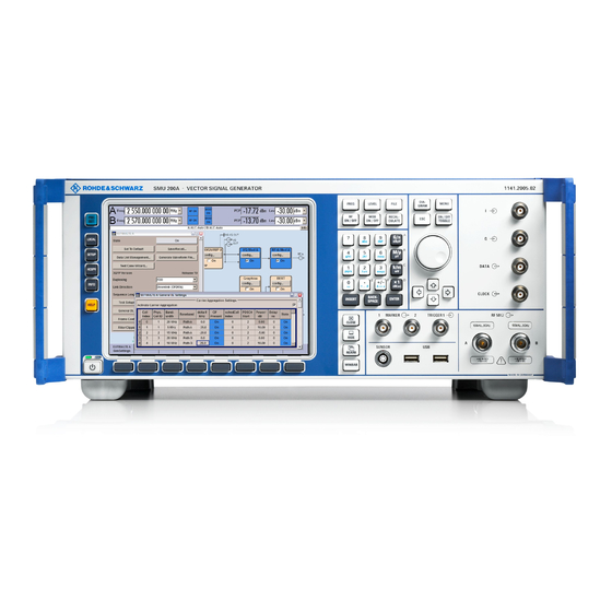
Contents "Putting into Operation" R&S SMU200A Figure 1-1 Front panel view 1007.9822.62 I-1.2... -
Page 26: Putting Into Operation
R&S SMU200A Introduction - Putting into Operation 1 Putting into Operation Introduction - Putting into Operation Chapter 1, "Putting into Operation" explains the control elements and connectors of the Vector Signal Generator R&S SMU with the aid of the front and rear views and describes how to put the instrument into operation. - Page 27 Legend for Front Panel View R&S SMU200A Display Display The large display clearly shows all main settings See chapter 3, section "Display" and signal generator states. The display is divided into three sections: - Frequency and level display with info line - Block diagram - Winbar with labelled softkeys The frequency and level display section with...
- Page 28 R&S SMU200A Legend for Front Panel View Keypad for data entry Keypad for data entry See chapter 3, section "Setting Parameters" 0...9 Entry of numeric values Entry of decimal point +/– Entry of sign Entry of letters Entry of a space *...
- Page 29 Legend for Front Panel View R&S SMU200A Keypad for data entry Keys for data entry See chapter 3, section "Selecting a Unit - The unit keys can either select a unit and thus Setting Parameters" determine the absolute value, or change the unit, i.e.
- Page 30 R&S SMU200A Legend for Front Panel View Keys for setting parameters See chapter 3, section "Setting Parameters", and chapter 4, section "RF Signal and Analog Mod - A Mod-RF A" FREQ Activates frequency entry. In the two-path mode, the frequency entry field that was active last is activated.
- Page 31 Legend for Front Panel View R&S SMU200A Keys for settings and navigation in the display and for setting parameters DIAGRAM Brings the block diagram to the See chapter 3, section foreground. Active menus are "Setting Parameters" minimized. Active menus are indicated by the buttons in the menu bar.
- Page 32 R&S SMU200A Legend for Front Panel View Keys for settings and navigation in the display and for setting parameters Keys for setting and navigation in the display and See chapter 3, section "Setting Parameters for setting parameters Arrow keys Vary the entry value or highlight a selected list item in the editing mode.
- Page 33 Legend for Front Panel View R&S SMU200A Trigger inputs and outputs TRIGGER 1 Input for triggering digital See data sheet and modulations and standards and ARB chapter 4, section "Global (paths A and B). Trigger/Clock/Input MARKER 1, 2 Outputs 1 and 2 for triggering and Settings –...
-
Page 34: Chapter 3: Operation
R&S SMU200A Legend for Front Panel View Connector for sensor Connector for R&S NRP-Zxx sensors (provided for future upgrades). Keys for setting the display CLOSE Closes the active menu. See chapter 3, section If the entry mode is active, changes "Menu Operation"... - Page 35 Legend for Front Panel View R&S SMU200A Fig. 1-2 Rear panel view 1007.9822.62 1.10...
-
Page 36: Legend For Rear Panel View
R&S SMU200A Legend for Rear Panel View Legend for Rear Panel View This section gives an overview of connectors on the rear panel of the R&S SMU. Each connector is briefly described and a reference is given to the chapters containing detailed information. For technical data of the connectors refer to the data sheet. - Page 37 Legend for Rear Panel View R&S SMU200A I OUT BAR / Q OUT BAR I OUT BAR / Q OUT BAR See data sheet and Differential (inverting) output (Option chapter 4, section R&S SMU-B16) for analog I/Q signal "Differential Outputs" (path A or path B).
- Page 38 R&S SMU200A Legend for Rear Panel View USB connectors type A USB (universal serial bus) interfaces of type A See chapter 1, section (host USB). "Connecting the Mouse" and chapter 8, – Connection of peripherals such as section "USB mouse, keyboard, printer Connection (USB and –...
- Page 39 Legend for Rear Panel View R&S SMU200A BERT BERT (Bit Error Rate Tester) input See data sheet and Input for data, clock and control chapter 4, section "Bit and Block Error Rate signals for bit and block error rate Measurements - BERT measurements, level 0.0128..1.998V.
- Page 40 R&S SMU200A Legend for Rear Panel View USER connector USER See data sheet and Input/output for configurable signals chapter 4, section "Global for triggering and control Trigger/Clock/Input The following signals can be applied Settings – Setup - to the connector: Environment"...
-
Page 41: Putting Into Operation
Putting into Operation R&S SMU200A Putting into Operation The following section describes the procedure for putting of the instrument into operation and the connection of peripherals such as printer and monitor. It contains general safety instructions for instrument operation. The installation of options and the firmware update are described in Chapter 4 of the Service Manual (supplied with the instrument on the CD-ROM). -
Page 42: Safety Instructions
R&S SMU200A Putting into Operation Safety Instructions General Precautions Caution! Prior to putting the instrument into operation, check the following: • The covers of the housing are in place and screwed on, • Vents are not obstructed. Make sure that the air can escape freely through the vents at the rear and at the sides. -
Page 43: Connecting The R&S Smu To The Ac Supply
Putting into Operation R&S SMU200A Connecting the R&S SMU to the AC Supply The R&S SMU is automatically matched to the applied AC voltage (see rear panel). There is no need to set the voltage manually or change fuses. The AC supply connector is at the rear of the unit (see below). -
Page 44: Start Display And Booting The R&S Smu
R&S SMU200A Putting into Operation Start Display and Booting the R&S SMU After instrument switch-on, the installed BIOS version and the processor characteristics are indicated for a few seconds in the start display. After this, the Windows XP Embedded operating system boots and then the instrument firmware. During booting of the instrument firmware, a selftest is performed. -
Page 45: Function Check
Function Check R&S SMU200A Function Check The signal generator automatically monitors the main functions when the instrument is switched on and continuously during operation. If a fault is detected, ERROR is displayed in the info line together with a brief error description. For in-depth identification of the error, press the key. -
Page 46: Windows Xp Embedded
R&S SMU200A Windows XP Embedded Windows XP Embedded Caution: Drivers and programs used in the instrument under Windows XP have been adapted to the signal generator. To avoid impairment of instrument functions, only the settings described below are permissible. Existing software must only be modified with update software released by Rohde &... -
Page 47: Connecting An External Keyboard
Connecting an External Keyboard R&S SMU200A Connecting an External Keyboard A commercial, external keyboard with USB interface can be connected to the R&S SMU. A keyboard simplifies entry of list items, comments, file names, etc. and is a prerequisite for convenient operation of Windows XP. -
Page 48: Connecting An External Monitor
R&S SMU200A Connecting an External Monitor Connecting an External Monitor Caution: The monitor must be connected only when the instrument is switched off (STANDBY) to prevent damage to the monitor and the R&S SMU. Do not modify the screen driver (Display type) and the display configuration since this will impair instrument operation. -
Page 49: Connecting The R&S Smu To A Network (Lan)
Connecting the R&S SMU to a Network (LAN) R&S SMU200A Connecting the R&S SMU to a Network (LAN) The R&S SMU is equipped with a network interface and can be connected to an Ethernet LAN (local area network). Provided the appropriate rights have been assigned by the network administrator and the Window XP firewall configuration is adapted accordingly, files can be transmitted via the network, and network resources, e.g. - Page 50 R&S SMU200A Connecting the R&S SMU to a Network (LAN) The Window XP operating system is protected by an activated firewall per default. The configuration of the firewall has to be adapted according to the required network communication needs. Networks using DHCP The R&S SMU is preconfigured for networks using DHCP (dynamic host configuration protocol).
- Page 51 Connecting the R&S SMU to a Network (LAN) R&S SMU200A 2. Click Control Panel and then Network and Internet Connections. 3. Click Network Connections at the bottom right of the Network and Internet Connections menu. 1007.9822.62 1.26...
- Page 52 R&S SMU200A Connecting the R&S SMU to a Network (LAN) 4. Click LAN Area Connection in the Network Connections menu (at the right) 5. On the General tab, select Internet Protocol (TCP/IP) in the field This connection uses the following items: and then click the Properties button. 1007.9822.62 1.27...
- Page 53 Connecting the R&S SMU to a Network (LAN) R&S SMU200A 6. In the Internet Protocol (TCP/IP) Properties menu, enter the IP address in the Use the following IP address: field (the complete data can be queried from the network administrator). Terminate the entry in all menus with OK.
- Page 54 R&S SMU200A Connecting the R&S SMU to a Network (LAN) 2. Click Properties and select the Computer Name tab in the menu. The computer name is displayed under Full Computer Name:. The name can be changed in the Change submenu. The Windows XP Firewall suppresses all network communication which is not initialized by the controller itself or which is defined as unwanted.
- Page 55 Connecting the R&S SMU to a Network (LAN) R&S SMU200A 3. Select tab Exceptions and activate check box File and Printer Sharing. Access to network drives depends on access rights and whether the drives in question have been enabled. The complete integration of the R&S SMU into a larger network with the necessary allocation of rights is highly complex and normally performed by a network administrator.
- Page 56 R&S SMU200A Connecting the R&S SMU to a Network (LAN) However, the hard disk of a computer also connected to the network can be accessed from the R&S SMU relatively easily. The only precondition for this is that the desired directory the R&S SMU should access is enabled on the remote computer.
-
Page 57: Manual Remote Control Via An External Controller
Manual Remote Control via an External Controller R&S SMU200A Manual Remote Control via an External Controller The R&S SMU can be manually controlled from an external PC via a network link. This allows convenient operation of the vector signal generator from the desktop although the instrument is integrated in a rack somewhere else. - Page 58 R&S SMU200A Manual Remote Control via an External Controller Enable Remote Desktop Connection on R&S SMU The configuration is performed in the Windows XP embedded menus. The operating system can only be accessed if an external keyboard is connected. A mouse is recommended for convenient operation of Windows XP.
- Page 59 Manual Remote Control via an External Controller R&S SMU200A Install Remote Desktop and Establish Connection on the Windows PC The Remote Desktop Connection program of Microsoft is available on the Internet for the Windows 95 operating system and its successors as a free-of-charge download. Following the instructions on the Internet, it can be loaded onto any external PC.
- Page 60 R&S SMU200A Manual Remote Control via an External Controller 4. Login data can be stored with the Save As button. If it is stored as a default.rdp file, the connection to the R&S SMU is offered as the default when the program is started.
- Page 61 Manual Remote Control via an External Controller R&S SMU200A Cut Manual Remote Control Connection via Remote Desktop The connection can be cut either on the R&S SMU or on the external PC. Cutting the connection does not disable it. It can be established again any time. Cutting the connection on the signal generator (requires external keyboard and mouse): 1.
-
Page 62: Configuration For Manual Remote Control Via Ultr@Vnc
R&S SMU200A Manual Remote Control via an External Controller Configuration for Manual Remote Control via Ultr@VNC The instrument is operated with the aid of the program Ultr@VNC. The program is included in operating system Linux/Unix. It is available as a free-of-charge download on the internet for operating system Window XP (http://ultravnc.sourceforge.net/download.htm). - Page 63 Manual Remote Control via an External Controller R&S SMU200A ! Select installation of all components ! Select all entries in the Additional Task Panel ! A successful installation is indicated by a message ! At the same time a warning is displayed stating that a password must be set. 1007.9822.62 1.38...
- Page 64 R&S SMU200A Manual Remote Control via an External Controller ! After clicking OK in the warning panel the Default Local System Properties panel opens. A password with a length of at least five digits must be entered. This password is used on the remote PC to access the R&S SMU.
- Page 65 Manual Remote Control via an External Controller R&S SMU200A Configuring Internet Connection Firewall for VNC Connection To enable manual remote control by other controllers in a local network via VNC connection, the connection must be specifically permitted in the firewall. 1.
- Page 66 R&S SMU200A Manual Remote Control via an External Controller 5. Activate check box Run Ultr@VNC SERVER in the Exception tab. Establish Manual Remote Control on the Linux/Unix PC The VNC program is available per default for Linux/Unix operating systems. Only three steps are necessary to establish the connection to the R&S SMU: 1.
- Page 67 Manual Remote Control via an External Controller R&S SMU200A Install VNC Viewer and Establish VNC Connection on the Windows PC The Ultr@VNC program is available on the Internet as a free-of-charge download. Following the instructions on the Internet, the program can be copied onto the external Windows PC. Only the program component VNC Viewer is required.
- Page 68 R&S SMU200A Manual Remote Control via an External Controller Cut Manual Remote Control Connection via Ultr@VNC The connection can be cut either on the R&S SMU or on the external PC. Cutting the connection does not disable it. It can be established again any time. Cutting the connection on the signal generator (requires external keyboard and mouse): 1.
-
Page 69: Using Norton Antivirus
Using Norton Antivirus R&S SMU200A Using Norton Antivirus Virus-protection software Symantec Norton Antivirus 2005 has been successfully tested for compatibility with the measurement instrument software on R&S SMU. However, Norton Antivirus may affect the behaviour of the instrument in terms of settling time or stability. - Page 70 R&S SMU200A Using Norton Antivirus 6. Select the Advanced and click Performance Settings 1007.9822.62 1.45...
- Page 71 Using Norton Antivirus R&S SMU200A 7. Click the Change button 1007.9822.62 1.46...
- Page 72 R&S SMU200A Using Norton Antivirus 8. Activate - Drive D: [DATA] - System managed size 9. Click the Set button 10. Click the Close button, the dialog closes Now program Norton Antivirus can be installed 1007.9822.62 1.47...
- Page 74 R&S SMU200A Contents "Getting Started" Contents - Chapter 2 "Getting Started" 2 Getting Started ................2.1 Introduction - Getting Started ................2.1 Baseband Section of R&S SMU................2.5 RF Section of R&S SMU ..................2.6 Applications of the Two-Path R&S SMU ............. 2.7 Two Baseband Generators, One RF Path ..........
- Page 75 Contents "Getting Started" R&S SMU200A 1007.9822.62 I-2.2...
-
Page 76: Getting Started
R&S SMU200A Introduction - Getting Started 2 Getting Started Introduction - Getting Started The main field of application of the R&S SMU is the generation of digitally modulated signals. The R&S SMU uses I/Q (vector) modulation. Digital data streams are converted to an I/Q baseband signal. The baseband signal is then D/A-converted and modulated onto the desired RF carrier frequency with the aid of an I/Q modulator. - Page 77 Introduction - Getting Started R&S SMU200A In the R&S SMU, a digitally modulated signal can be generated in several ways: 1. The I/Q signal is generated internally in the R&S SMU. In this case the instrument must be equipped with at least one baseband generator (option R&S SMU-B10) and at least one baseband main module (option R&S SMU-B13).
- Page 78 R&S SMU200A Introduction - Getting Started 2. The I/Q signal is generated by an external instrument and coupled in via the baseband input module (option R&S SMU-B17, Baseband Input). The baseband input module is capable of processing analog I/Q signals. If options are installed for internal baseband generation, external and internal baseband signals can be added (possibly with frequency offset).
- Page 79 Introduction - Getting Started R&S SMU200A 3. An external analog I/Q signal is directly applied to the I/Q modulator of the R&S SMU (Analog Wideband I/Q operation). In this mode, the entire bandwidth of the I/Q modulator can be utilized. The various capabilities of the baseband section (AWGN, addition of signals, etc) are disabled, however.
-
Page 80: Baseband Section Of R&S Smu
R&S SMU200A Baseband Section of R&S SMU Baseband Section of R&S SMU The baseband section of the R&S SMU is fully digital and contains the hardware for generating and processing I/Q signals. The baseband section may contain two paths. Baseband generator (option R&S SMU-B10): The generator produces baseband signals. It contains modules for real time signal generation and an arbitrary waveform generator (ARB). -
Page 81: Rf Section Of R&S Smu
RF Section of R&S SMU R&S SMU200A RF Section of R&S SMU The RF section of the R&S SMU may also contain two paths. An RF path is configured by installing a frequency option that comprises all required modules including synthesizer, output section with I/Q modulator and attenuator. -
Page 82: Applications Of The Two-Path R&S Smu
R&S SMU200A Applications of the Two-Path R&S SMU Applications of the Two-Path R&S SMU The modular design of the R&S SMU allows the instrument to be equipped with two paths. This allows a multitude of applications to be performed for which several signal generators were previously required. -
Page 83: One Baseband Path And Two Rf Paths
Applications of the Two-Path R&S SMU R&S SMU200A One Baseband Path and Two RF Paths Possible applications: • Generation of a modulated signal on path A and a CW interferer on path B Fig. 2-5 Operation of R&S SMU with one baseband generator and two RF paths 1007.9822.62... -
Page 84: Fully Equipped Two-Path Instrument
R&S SMU200A Applications of the Two-Path R&S SMU Fully Equipped Two-Path Instrument Possible applications: • Generation of a wanted signal and an interfering signal for receiver tests • Generation of multicarrier signals with extremely wide bandwidth (>80 MHz) • Generation of fading scenarios with external I/Q signal Fig. -
Page 85: Description Of Individual Diagram Blocks
Description of Individual Diagram Blocks R&S SMU200A Description of Individual Diagram Blocks Available Blocks Block Function of block Status display in the block Effect of TOGGLE ON/OFF key Baseband source is configured Selected modulation Switches the selected modulation Baseband A or B and activated (digital standard, digital modulation or ARB) on or off. - Page 86 R&S SMU200A Description of Individual Diagram Blocks In this block, the (first) baseband source is configured and activated. The block is displayed only if a baseband generator (option R&S SMU-B10, Universal Coder and ARB) is available in the instrument. Depending on the installed software options, various digital standards, user-configured digital real time modulation or the built-in waveform generator (ARB) can be selected.
- Page 87 Description of Individual Diagram Blocks R&S SMU200A AWGN/IMP A block This block is displayed only if a baseband main module is installed. In this block (digital) I/Q impairments for baseband path A can be set. With the aid of the software for AWGN generation (option R&S SMU-K62), an (additive) noise signal can be produced in path A.
-
Page 88: Blocks Of The Rf Section
R&S SMU200A Description of Individual Diagram Blocks Blocks of the RF Section I/Q Mod A block The (first) I/Q modulator is configured in this block. Also the Analog Wideband I/Q mode can be selected here, which allows external I/Q signals to be directly applied to the I/Q modulator, i.e. not via the baseband section. - Page 89 Description of Individual Diagram Blocks R&S SMU200A The active analog modulation modes are displayed in the block. The key switches the TOGGLE ON/OFF RF signal of the path on and off. When the signal is switched off, the switch before the RF output symbol is open.
-
Page 90: Example Of Setup
R&S SMU200A Example of Setup Example of Setup A central element of the R&S SMU display is the block diagram that illustrates the signal flow. Each block represents an important section of signal generation. Thus the user always knows the position at which a parameter has an effect in the signal flow. - Page 91 Example of Setup R&S SMU200A Step 2: Select and activate digital modulation Select the Baseband A block by turning the rotary knob. Press the rotary knob to open the menu where the digital modulation can be selected (different modulation modes are available depending on the options installed).
- Page 92 R&S SMU200A Example of Setup Press the rotary knob to open the Custom Dig. Mod. menu. Select the Symbol Rate parameter by turning the rotary knob, and then enter the desired symbol rate with the aid of the numeric keypad and the unit keys.
- Page 93 Example of Setup R&S SMU200A Select the Coding parameter by turning the rotary knob. Press the button to open the selection list. Select Off by turning the rotary knob and press it to activate the selected item. Set Modulation Type QPSK and Filter Root Cosine with Roll Off Factor 0.3 in the same...
- Page 94 R&S SMU200A Example of Setup Finally, switch on digital modulation by selecting State On. Press the DIAGRAM key to display the complete block diagram. To indicate the active state, the Baseband block is displayed in blue. The I/Q Mod block is automatically activated.
- Page 95 Example of Setup R&S SMU200A The menu can be displayed in the foreground by clicking the softkey below the button in the Windows list. Press the key to HIDE minimize the menu again. Step 3: Set frequency and level and activate RF signal Press the key to FREQ...
- Page 96 R&S SMU200A Example of Setup Enter the level in the same way after pressing key. LEVEL Press the DIAGRAM to display the complete block diagram. Select the RF/A Mod block by turning the rotary knob and activate it by pressing the key.
- Page 97 Example of Setup R&S SMU200A Step 4: Select graphics display of I/Q signal Select the Graphics block and open the respective menu by turning the rotary knob. Activate display of the I/Q diagram by selecting State On with the rotary knob.
- Page 98 Contents "Manual Operation" R&S SMU200A Contents - Chapter 3 "Manual Operation" 3 Manual Operation................3.1 Introduction - Manual Operation................3.1 Operating Concept ....................3.1 Display......................... 3.7 Frequency and Level Setting - Display........... 3.7 Status Information and Messages - Display........... 3.8 Info Window - Display................3.9 Block Diagram - Display ...............
- Page 99 R&S SMU200A Contents "Manual Operation" 1007.9822.62 I-3.2...
-
Page 100: Manual Operation
R&S SMU200A Introduction - Manual Operation 3 Manual Operation Introduction - Manual Operation The Vector Signal Generator R&S SMU can be operated intuitively either via the interactive block diagram or via a menu tree. All menus are in the form of windows that can be operated in the same way. - Page 101 Operating Concept R&S SMU200A Operation via the graphics interface Menus are assigned to the specific function blocks in the block diagram. The function blocks represent elements of signal generation, e.g. the baseband block which contains all menus required for baseband signal configuration.
- Page 102 R&S SMU200A Operating Concept Operation corresponds to the Windows concept To offer the user a familiar environment, operation is very similar to operation of Windows user interfaces. All menus and tables are made up of known elements, e.g. selection lists, check boxes, or entry fields.
- Page 103 Operating Concept R&S SMU200A The Winbar gives an overview of menus and simplifies their access. The menus are displayed on top of the block diagram but they can be "hidden", i.e. displayed in the form of a button in the Winbar at the lower end of the screen ( key).
- Page 104 R&S SMU200A Operating Concept Each help page is part of a comprehensive online help function which can be called by means of an index, a content tree or the buttons. Previous Next Messages indicate the current instrument state A great variety of different messages such as status messages, error messages, warnings or information are displayed in the header field of the screen.
- Page 105 Operating Concept R&S SMU200A Graphical display of output signal in a diagram The output signal can be graphically displayed in a number of diagrams. This allows a fast check of signal characteristics. Zoom functions and the insertion of a reference trace permit in-depth evaluation without an external analyzer being required.
-
Page 106: Display
R&S SMU200A Display Display The display shows the current signal generator state and offers graphical elements for direct operation. It is divided into three sections: • The frequency and level display with info line indicates the main output signal parameters and reports the current state with status, error and warning messages. -
Page 107: Status Information And Messages - Display
Display R&S SMU200A Status Information and Messages - Display The status information and messages are displayed in the header section of the screen. The messages differ with respect to their importance (errors, warnings, info) and the time of their appearance (brief and permanent messages). -
Page 108: Info Window - Display
R&S SMU200A Display Info Window - Display A few operating states and the current message are displayed in the info line (see also chapter 9 "Error Messages"). The info window with a list of current permanent messages and a detailed description of each message can be opened with the key. -
Page 109: Block Diagram - Display
Display R&S SMU200A Block Diagram - Display The block diagram shows provided options, signal configuration and the currently selected signal flow of the generator with inputs and outputs used. Signal generation can be completely operated from the block diagram. The highlighted function block can be directly switched on and off with the TOGGLE key. - Page 110 R&S SMU200A Display Clicking the rotary knob (front panel) or the config... button (mouse) opens the associated setting menu. In all function blocks where the signal flow can be influenced, the top menu level for setting signal routing parameters is offered. The input/output symbols in the block diagram show the currently used inputs and outputs of the signal generator.
-
Page 111: Winbar And Softkeys - Display
Display R&S SMU200A Symbols and lines are displayed in different colors depending on their function. • The baseband signal is indicated by a three line arrow, the I- and Q- components of the signal by a single-line arrow. • Addition of signals is indicated by the summation sign. -
Page 112: Menu Structure - Display
R&S SMU200A Display Menu Structure - Display The parameters are set in the menus. Menus are called either via the function blocks in the diagram or by means of the key. The menus are displayed on top of the block diagram. If the menu buttons MENU assign menu-specific functions to the softkeys, the Winbar is hidden. - Page 113 Display R&S SMU200A Selection field button indicates that a selection can be made from a list. The fold-down selection list is displayed below the selection field. Depending on the number of entries, the full list or only part of it is shown.
- Page 114 R&S SMU200A Display Tables Tables are made up of a header, which normally contains the column labels, and lines containing the text. Graphical display Graphical displays show signal characteristics and in some of them the element to be set can be selected.
-
Page 115: Graphical Display Of Output Signal Characteristics
Display R&S SMU200A Graphical Display of Output Signal Characteristics The graphical display of the output signal enables the user to rapidly check signal characteristics without connecting an analyzer. Zoom functions and the display of a reference trace allow in-depth evaluation. The diagram is displayed on top of the block diagram. It can be minimized and called in the same way as a menu. -
Page 116: Setting Parameters
R&S SMU200A Setting Parameters Setting Parameters The R&S SMU offers several and sometimes alternative possibilities for setting parameters. Operation is possible from the front panel, with the aid of a mouse and/or from a PC keyboard. Operation of the R&S SMU with the aid of these control media is shown in the tables below. Frequency and level are directly set in the header area of the display using the keys. -
Page 117: Selecting A Control Element - Setting Parameters
Setting Parameters R&S SMU200A Frequency/level field: The cursor is set on the previously active menu or, if no menu was active, on the first function block in the diagram. Function block in the diagram: The cursor is set on the first menu in the Winbar. If no menus are open, the current cursor position remains unchanged. -
Page 118: Selecting And Exiting A Menu Area - Setting Parameters
R&S SMU200A Setting Parameters Selecting and Exiting a Menu Area - Setting Parameters Some menus are organized in areas. The cursor can be moved either only within an area or between the higher-level menu areas. This applies to the File Select menus when files are saved or loaded. When the menu is called, one of the menu areas is highlighted by a blue frame. -
Page 119: Entering A Value - Setting Parameters
Setting Parameters R&S SMU200A • The left/right cursor keys first shift the entry focus within the menu range form left to right (or vice versa); in the example, from the directory tree to the file list. Press again and the entry focus is shifted up one menu level.Clicking the rotary knob (= Enter) performs a setting. - Page 120 R&S SMU200A Setting Parameters • Editing a value in the overwrite mode: Clicking the rotary knob (= Enter) activates the editing mode. Set the cursor on the number to be varied using the left/right arrow keys. In the overwrite mode, the cursor is blue. The highlighted value is overwritten by clicking a numeric key.
-
Page 121: Selecting A Unit - Setting Parameters
Setting Parameters R&S SMU200A Selecting a Unit - Setting Parameters The entry of a numeric value can be terminated by pressing a unit key on the front panel, selecting a unit in the selection field next to the value or by clicking the rotary knob (= Enter). The unit is assigned in different ways: Terminating the value entry by pressing the unit key When the entry is terminated with a unit key on the front panel, the key assigns the unit to the value. -
Page 122: Selecting A Value From A List - Setting Parameters
R&S SMU200A Setting Parameters Function Front panel PC keyboard Mouse Assigns a unit To terminate the entry, press To terminate the entry press Select unit in the field at the one of the key combinations right of the value before one of the unit keys ALT + F9/ + F10/+ F11/+ F12 entering the value (for list... -
Page 123: Terminating Entries - Setting Parameters
Setting Parameters R&S SMU200A Terminating Entries - Setting Parameters Variations by means of the rotary knob are immediately set, e.g. RF frequency variation. All other parameter settings have to be confirmed by a pressing the rotary knob or one of the unit keys (see also section "Selecting a Unit", page 3.22). -
Page 124: Restoring The Previous Value - Setting Parameters
R&S SMU200A Setting Parameters Restoring the Previous Value - Setting Parameters Parameter variations with the rotary knob are immediately set and therefore not reversible. Normally, values cannot be restored also in the case of mouse control because no explicit confirmation is required in this case and entries are automatically confirmed when the entry or selection field is exited. -
Page 125: Menu Operation
Menu Operation R&S SMU200A Menu Operation Menus are operated with the aid of the Winbar buttons or front-panel softkeys and with the HIDE keys on the front panel. CLOSE DIAGRAM REARR If the Winbar is covered by a menu, it can be called to the front with the key. -
Page 126: Editors
R&S SMU200A Editors Editors The R&S SMU provides user-friendly editors for defining data lists as well as control and marker signals. Lists containing frequency and level value pairs are used for the list mode and the user-defined level correction. Internally generated data lists can be used for digital modulation and digital standards; the same applies to internally defined control and marker signals. - Page 127 Editors R&S SMU200A Function Front panel PC keyboard Mouse Call up editor. Use the rotary knob or the Mark the Edit xxx Data... Click the Edit xxx Data... cursor keys to mark the Edit button in the individual menu button in the individual menu. xxx Data...
-
Page 128: Data Editor
R&S SMU200A Editors Function Front panel PC keyboard Mouse ENTER key. Enter the file name in the File Enter the file name in the File Select menu and select the Select menu and select the Enter the file name in the File directory (see section "File directory (see section... - Page 129 Editors R&S SMU200A Function Front panel PC keyboard Mouse Call up editor. Mark the Edit Data List... Click the Edit Data List... Use the rotary knob or the cursor keys to mark the Edit button in the list management button in the list management The cursor marks the start Data List...
-
Page 130: Control And Marker List Editor
R&S SMU200A Editors Function Front panel PC keyboard Mouse Display and edit the values Mark the Hex button and Click the Hex button. Use the rotary knob or the in hexadecimal form. cursor keys to mark the Hex press the Enter key. button, click the rotary knob Each four bits are displayed or press the ENTER key. - Page 131 Editors R&S SMU200A • The upper area displays the signal (in the example, the GSM slot) for which the marker signals are to be defined. On the left side, the available signals (marker and control signals) are listed and colour-coded. •...
- Page 132 R&S SMU200A Editors If another change produces effective transition, this ramp will be regenerated. • An existing ramp can be shifted to any positions. The transitions are adjusted accordingly. • To make the setting easy, a selection of preset ramp characteristics is offered in the Preset Signal area.
- Page 133 Editors R&S SMU200A Function Front panel PC keyboard Mouse Shift ramp. Use the rotary knob or the Use the cursor keys to move After double-clicking the cursor keys to move the the cursor to the ramp cursor, click it once again The ramp transition depends cursor to the ramp position;...
-
Page 134: Help System
R&S SMU200A Help system Help system The R&S SMU is equipped with a context-sensitive help function. A help page is available for each parameter and can be called any time during instrument operation. The context-sensitive page which is opened with the key is part of a comprehensive help system. - Page 135 Help system R&S SMU200A Function Front panel PC keyboard Mouse Activate the link Select link with rotary knob or Select link using the arrow Click link. arrow keys and activate by keys and activate with the The help system branches to clicking the rotary knob or Enter key.
-
Page 136: File Management
R&S SMU200A File Management File Management The R&S SMU uses files to save all instrument data, i.e. system and user data. The user data includes saved instrument settings, data for the different digital standards, lists for the List mode and the user correction as well as the waveforms for the arbitrary waveform generator. -
Page 137: File Select Menu
File Management R&S SMU200A The files are differentiated according to their extensions; each type of file is assigned a specific file content. The extension is usually of no consequence to the user since access to the files occurs in the individual menus where only the relevant type of file is available. -
Page 138: File Manager
R&S SMU200A File Management When a file is saved or created, its name is user-selectable; the extension is assigned automatically and cannot be entered. The file is saved to the selected path. Operation is similar to the operation of menus with several areas (see section "Selecting and Exiting a Menu Area - Setting Parameters", page 3.19): By using the rotary knob or cursor keys, the area is... - Page 139 File Management R&S SMU200A or via the button in the File Select window. File Manager The File Manager can also be called up in the Save/Recall - Setup-Settings menu. In the upper area, File Type, the File Manager allows the type file selection to be displayed. This can be used to process either all files (all files (*:*) selection) or a specific selection of files (e.g.
- Page 140 R&S SMU200A File Management Table 3-1 List of file extensions for user files the R&S SMU assigns automatically List type Contents File suffix Instrument State Instrument State Instrument settings *.savrcl User Correction User Correction User-defined level correction values *.uco List Mode List User-defined frequency/level value pairs *.lsw...
-
Page 141: Manual Remote Control
Manual Remote Control R&S SMU200A Manual Remote Control The R&S SMU can be remote-controlled from an external PC. This allows convenient operation of the vector signal generator from the desktop although the instrument is integrated in a rack somewhere else. Manual remote control in contrast to remote control does not use remote-control commands but separate Windows software which is installed on the external PC. -
Page 142: Legend Of Front-Panel Controls
R&S SMU200A Legend of Front-Panel Controls Legend of Front-Panel Controls The following table lists all key functions available on the front panel. Key combinations used on the PC keyboard to trigger key functions on the instrument front panel are also described. Keyboard labels are described in alphabetical order. - Page 143 Legend of Front-Panel Controls R&S SMU200A Front-panel key Key of PC keyboard Function HELP Opens/closes context-sensitive help. HIDE CTRL+ H Minimizes the active menu. Pressing the respective button in the Winbar opens the menu again. INFO CTRL + I Opens/closes the info window INSERT Activates the insert mode.
- Page 144 R&S SMU200A Legend of Front-Panel Controls In addition, the Windows XP operating system provides a keyboard emulation that can be used for system settings if no external keyboard but a mouse is available. It is called in the START - Programs - Accessories - Accessibility menu, selection On-Screen Keyboard.
- Page 146 R&S SMU200A Contents "Instrument Functions" Contents - Chapter 4 "Instrument Functions" Instrument Functions ................4.1 Overview of Instrument Functions............... 4.1 General Instrument Settings ..............4.4 Overview of General Instrument Settings ............4.4 Default Instrument Settings - Preset Key ............4.4 General Configuration of Instrument - Setup Key ..........4.5 Internal Adjustments - Setup-System.............
- Page 147 Contents "Instrument Functions" R&S SMU200A Graphical Display of Signal Characteristics ............4.30 Graphics Settings Menu ............... 4.31 Softkey Bar of Graphics Window............4.34 Signal Displays - Graphics ................4.37 I/Q Diagram - Graphics ................ 4.37 Vector Diagram - Graphics..............4.38 Constellation Diagram - Graphics ............
- Page 148 R&S SMU200A Contents "Instrument Functions" Modulation Sources................4.117 Simultaneous Operation of Several Modulations or Other Operating Modes....................4.118 Amplitude Modulation - AM ................4.118 Amplitude Modulation Menu............... 4.119 Broadband Amplitude Modulation - BB-AM ............ 4.122 Broadband Amplitude Modulation Menu ..........4.122 Pulse Modulation .....................
- Page 149 Contents "Instrument Functions" R&S SMU200A Birth Death Propagation Path Graph - Fading ........4.205 Moving Propagation - Fading ............. 4.206 Insertion Loss Configuration ... - Fading ..........4.209 Baseband Signal - Baseband............4.212 Introduction - Baseband Signal ............... 4.212 Signal Routing and Frequency Shifting ............4.213 Data and Signal Sources in Baseband ............
- Page 150 R&S SMU200A Contents "Instrument Functions" ARB MOD Main Menu................ 4.284 Trigger/Marker/Clock - ARB MOD Menu..........4.293 Sine Test Signals - ARB MOD Menu ..........4.301 Create Multi-Segment Waveforms - ARB Menu ........ 4.302 Typical Applications for Multisegment Waveforms - ARB Menu..4.307 Create Multi-Carrier Waveforms - ARB Menu........
- Page 151 Contents "Instrument Functions" R&S SMU200A Summation and Filtering - 3GPP FDD ..........4.393 Multicode - 3GPP FDD............... 4.393 3GPP FDD Menu..................... 4.394 General Settings for 3GPP FDD Signals ........... 4.395 Configure Base Station or UE - 3GPP FDD........4.400 Filtering, Clipping, ARB Settings - 3GPP FDD........4.406 Trigger/Marker/Clock - 3GPP FDD.............
- Page 152 R&S SMU200A Contents "Instrument Functions" Channel Table- DPDCH UE - 3GPP FDD.......... 4.530 E-DPDCH Settings - UE - 3GPP FDD ..........4.533 HSUPA FRC Settings - UE - 3GPP FDD ........... 4.538 Global Enhanced Channel Settings - UE1 - 3GPP FDD....4.541 Channel Coding - DPDCH Enhanced UE 1 - 3GPP FDD....
- Page 153 Contents "Instrument Functions" R&S SMU200A Test Case 8.3.2 - Demodulation of DCH in Multipath Fading Case 2 Conditions................... 4.599 Test Case 8.3.3 - Demodulation of DCH in Multipath Fading Case 3 Conditions................... 4.599 Test Case 8.3.4 - Demodulation of DCH in Multipath Fading Case 4 Conditions...................
- Page 154 R&S SMU200A Contents "Instrument Functions" Constellation of I/Q Signals - Downlink ..........4.625 Power Control - CDMA2000 - Downlink and Uplink......4.626 CDMA2000 Menu .................... 4.627 General Settings for CDMA2000 Signals........... 4.628 Configure Base Station or Mobile Station - CDMA2000 ....4.634 Filtering, Clipping, ARB Settings - CDMA2000 ........
- Page 155 Contents "Instrument Functions" R&S SMU200A General Settings for WiMAX Signals ..........4.735 Frame Configuration OFDM - WiMAX..........4.744 Burst Table OFDM- WiMAX ............... 4.748 Frame Graph OFDM - WiMAX ............4.752 Show Active Carriers OFDM - WiMAX..........4.752 FCH Configuration Downlink OFDM- WiMAX ........4.753 Generate UL-MAP Uplink OFDM- WiMAX.........
- Page 156 R&S SMU200A Contents "Instrument Functions" General Settings for TD-SCDMA Signals .......... 4.825 Filtering, Clipping, ARB Settings - TD-SCDMA........4.833 Power Ramping- TD-SCDMA............. 4.837 Trigger-Marker-Clock - TD-SCDMA ........... 4.838 Predefined Settings - TD-SCDMA............4.845 Cell Configuration - TD-SCDMA............4.847 Enhanced Channels Settings – TD-SCDMA........4.850 Enhanced Channel Settings –...
- Page 158 R&S SMU200A Overview of Instrument Functions Instrument Functions Overview of Instrument Functions This chapter explains the functions of the vector signal generator and the options available in the setting menus. The associated IEC/IEEE-bus command is specified for each parameter (where applicable). The description begins with the general instrument settings which do not directly affect signal generation.
- Page 159 Overview of Instrument Functions R&S SMU200A The integrated bit error rate and block error tester is configured and activated in the BERT function block: • Bit error rate and block error measurement (section 'Bit and Block Error Rate Measurements - BERT Block" on page 4.43' The RF signal is configured and the analog modulations activated in the RF/A Mod function block: •...
- Page 160 R&S SMU200A Overview of Instrument Functions • Digital standard GSM/EDGE (section "Digital Standard GSM/EDGE", page 4.337) • Digital standard 3GPP FDD (WCDMA) (section "Digital Standard 3GPP FDD ", page 4.383) • Tests on Base Stations (section "Tests on Base Stations in Conformance with the 3G Standard 3GPP-FDD", page 4.553) •...
- Page 161 Overview of General Instrument Settings R&S SMU200A General Instrument Settings Overview of General Instrument Settings The section "General Instrument Settings" describes the settings which do not directly affect signal generation. Most of these settings can only be accessed by means of menus which are opened using keys. This does not apply to the graphical representation of output signals which is activated in the Graphics function block, or settings which can additionally be called up in the menus of the function blocks, e.g.
- Page 162 R&S SMU200A General Configuration of Instrument - Setup Key The following table gives an overview of the presets for the most important generator settings. The other presets can be found in the preset tables of the individual menus and the information accompanying the IEC/IEEE-bus commands.
- Page 163 General Configuration of Instrument - Setup Key R&S SMU200A Internal Adjustments - Setup-System The R&S Vector Signal Generator is extremely accurate thanks to the integrated procedures for adjustments. All internal adjustments for which no external measuring equipment is needed can be started in the Internal Adjustments...
- Page 164 R&S SMU200A General Configuration of Instrument - Setup Key Path - Setup Internal Selects the path for which the following adjustments are to be Adjustments performed. Remote-control command: n.a. (With remote control, the path is selected using the numerical suffix under CALibrate.) Adjust Synthesis - Setup Performs all adjustments which affect the frequency of the selected Internal Adjustments...
- Page 165 General Configuration of Instrument - Setup Key R&S SMU200A Adjust I/Q Modulator Full Starts the adjustment for the I/Q modulator for the entire frequency Range- Setup Internal range. The I/Q modulator is adjusted with respect to carrier leakage, Adjustments I/Q imbalance and quadrature. Remote-control command: CAL1:IQM:FULL? Adjust Baseband Input-...
- Page 166 R&S SMU200A General Configuration of Instrument - Setup Key Gui Update... - Setup/System The Start/Stop Gui Update menu... provides the possibility to switch off update of the displayed parameters in order to increase speed for certain settings. The indicated values are not updated and may therefore differ from the intern, used values. Remote-control command: SYST:DISP:UPD OFF Software / Options...
- Page 167 General Configuration of Instrument - Setup Key R&S SMU200A The Firmware section of the menu shows the firmware version and the version of the software platform. The tables in the sections Hardware, Software and WinIQSIM list the installed hardware and software options.
- Page 168 R&S SMU200A General Configuration of Instrument - Setup Key Test Point... - Setup-Test The Test Point... menu provides access to the test points available in the instrument. When activated, the voltage of the selected test point is measured and displayed. A detailed description of the test points can be found in Chapter 3 of the Service Manual (supplied with the instrument).
- Page 169 General Configuration of Instrument - Setup Key R&S SMU200A Select Test Point - Setup Calls the submenu for selecting the test point. The currently selected key is shown next to the key. Remote-control command: DIAG1:POIN:CAT? (Command lists all test points) DIAG1:POIN? 'DIAG_IQOP3_LCM_CAL_I' (With remote control, voltage measurement starts as soon as the test point is selected)
- Page 170 R&S SMU200A General Configuration of Instrument - Setup Key Global Trigger/Clock/External Input Settings - Setup- Environment The Global Trigger/Clock/External Inputs menu can be opened using the key under SETUP MENU the Environment menu as well as in all clock and trigger menus of the Baseband function block. Error! Bookmark not defined.
- Page 171 General Configuration of Instrument - Setup Key R&S SMU200A Threshold Trigger/Control Sets the high/low threshold in volts for the trigger and control signal Input - Global Settings inputs of the baseband section. The setting affects the TRIGGER 1 and 2 inputs (BNC connectors at the front and rear of the instrument) and the CW, BURST and LEV_ATT inputs (AUX I/O interface at the rear of the instrument).
- Page 172 R&S SMU200A General Configuration of Instrument - Setup Key Clock Input Slope - Global Sets the polarity of the active slope of an externally applied bit clock Settings pulse or symbol clock pulse. This setting affects the CLOCK input (BNC connector at the front of the instrument).
- Page 173 General Configuration of Instrument - Setup Key R&S SMU200A User Marker - AUX IO - Setup-Environment-Global...Settings The R&S Vector Signal Generator provides four USER interfaces which can be freely assigned a selection of signals and which can be configured as both inputs and outputs. Error! Bookmark not defined.
- Page 174 R&S SMU200A General Configuration of Instrument - Setup Key The polarity of the blank marker is selected in the No Signal (Blank) Marker section. AUX I/O Connector An illustration of the AUX I/O interface is shown. The pins are color- Mapping - AUX IO coded.
- Page 175 General Configuration of Instrument - Setup Key R&S SMU200A Connection Description 27 - CW MODE Signal input for controlling the switchover between the modulated unmodulated signal with activated external modulation/CW switching in the Custom Digital Modulation menu (CW control signal). Signal output for the CW control signal with internal source selected.
- Page 176 R&S SMU200A General Configuration of Instrument - Setup Key The polarity of the No Signal (Blank) Marker is set in the No Signal (Blank) Marker section. Selects the polarity of the No Signal Marker. If Positive is selected, Polarity - No Signal Marker the signal is high (2.5 V) when the marker is active;...
- Page 177 General Configuration of Instrument - Setup Key R&S SMU200A Protection - Setup-Protection The Protection menu provides access to the unlocking of protected service functions (authorized personnel of R&S Service Departments only). To unlock the lock-out, the correct password has to be entered.
- Page 178 R&S SMU200A Switching to Manual Control - Local Key Switching to Manual Control - Local Key In remote control mode a status message appears in the display header. The rest of the display remains unchanged and shows the current instrument status, i.e. the status which exists under the remote control settings.
- Page 179 Help System - Help Key R&S SMU200A Help System - Help Key key opens a browser window containing a context-sensitive description of the highlighted HELP parameter. The context-sensitive page which is opened with the key is part of a comprehensive help system. HELP It is possible to move from this context-sensitive page to any page of the help system.
- Page 180 R&S SMU200A Help System - Help Key The softkeys are used to determine the entry focus for front panel operation, to select the content of the navigation window and to change the font size. To determine the entry focus for front panel operation the Cursors UP/Down are used.
- Page 181 Storing and Loading Instrument Data - File Key R&S SMU200A Storing and Loading Instrument Data - File Key The R&S Vector Signal Generator allows complete instrument settings to be stored in files on the hard disk. Defined and complex instrument settings can then be reproduced at any time by loading this data. If required, these settings can be loaded to various signal generators.
- Page 182 R&S SMU200A Storing and Loading Instrument Data - File Key File Menu The settings available in the File menu depend on the operation selected under Select Operation. Select Operation - File Selects the file function. Save… Calls the menu for storing the current instrument setting.
- Page 183 Storing and Loading Instrument Data - File Key R&S SMU200A Directory - File Selects the directory in which the file is to be stored. The window opposite lists all settings files in this directory. A new directory can be created in the File Manager (File Manager button).
- Page 184 R&S SMU200A Storing and Loading Instrument Data - File Key Loading Instrument Settings - File If Recall is selected under Select Operation, the File menu provides options for loading complete instrument settings. Here it is possible to select whether the current or stored RF frequency and RF level settings are to be used.
- Page 185 Storing and Loading Instrument Data - File Key R&S SMU200A Load the selected configuration. Recall - File If an instrument setting in which a sweep was activated is stored, the sweep is started when the recall command is called. If an instrument setting which accesses lists is stored, this list is also loaded.
- Page 186 R&S SMU200A Storing and Loading Instrument Data - File Key Selects the directory in which the file to be deleted or copied is Directory - File located. The window to the right lists all files in this directory. The file Management to be deleted or copied can be highlighted.
- Page 187 Graphical Display of Signal Characteristics R&S SMU200A Graphical Display - Graphics Graphical Display of Signal Characteristics The R&S Vector Signal Generator can be used to graphically display the generated baseband signal. A selection of different signal displays assists the user in assessing and checking the increasingly complex modulation signals.
- Page 188 R&S SMU200A Graphical Display of Signal Characteristics In the case of two-path instruments, the baseband signals of both paths can be displayed simultaneously. Graphics Settings Menu The Graphics Settings menu for selecting the graphical display of the output signal is opened either in the Graphics function block or in the menu with the same name which is opened using the key.
- Page 189 Graphical Display of Signal Characteristics R&S SMU200A Activates the "smart graphics". Smart Graphics - Graphics The graphic is displayed in a small window which is roughly the size of Settings a block. These windows are displayed permanently in the block diagram until they are deactivated, and allow basic checking of the signal.
- Page 190 R&S SMU200A Graphical Display of Signal Characteristics (only if Code Domain (3GPP FDD DL) is selected) Sets the Scrambling Code - scrambling code if the Code Domain display is selected. Since it is Graphics Settings possible to select a different scrambling code in the menu for each of the 4 base stations and it is also possible to display an external signal, the scrambling code for which the display is to be generated must be explicitly specified here.
- Page 191 Graphical Display of Signal Characteristics R&S SMU200A Softkey Bar of Graphics Window At the bottom of each graphics window there are buttons for freezing and zooming the display and for defining and activating a reference curve. Freezes the current display. Clicking the button again reactivates the normal, permanently updated display.
- Page 192 R&S SMU200A Graphical Display of Signal Characteristics Displays the reference curve(s). All defined reference curves are Show ref displayed simultaneously (see the description of the Copy to ref button). The reference curves are displayed together with the current signal. They allow visual comparison of two or more signals with different settings, e.g.
- Page 193 Graphical Display of Signal Characteristics R&S SMU200A The comments entered for the defined reference Display area curve are shown in the display area next the assigned color. A maximum of five colors (and reference curves) are available. If no reference curve is assigned to a particular color, the comment <empty>...
- Page 194 R&S SMU200A Signal Displays - Graphics Signal Displays - Graphics All signal displays which are used for analyzing a baseband signal can be selected. A number of signal displays are only available if the corresponding signal is generated, e.g. Code Domain only available for (W)CDMA signals.
- Page 195 Signal Displays - Graphics R&S SMU200A Vector Diagram - Graphics The Q component is displayed over the I component in the vector diagram. Each point is determined by a vector. The amplitudes of the signal components scaled to the peak envelope power (PEP) are plotted on the X and Y axis (minimum scaled amplitude = -1;...
- Page 196 R&S SMU200A Signal Displays - Graphics Constellation Diagram - Graphics In the constellation diagram, the Q component is also displayed over the I component. However, only the values at the constellation points (signal value at the ideal scanning instant of the symbol) are displayed, i.e.
- Page 197 Signal Displays - Graphics R&S SMU200A Eye Diagram - Graphics The eye diagram displays synchronized and superimposed sections of either the inphase or quadrature components of the signal. The display width (eye length) is set at 2 symbols; several hundred curve segments are superimposed. The time (in the range -/+ 1 symbol) is plotted on the X axis, and the amplitude scaled to the peak envelope power (PEP) is plotted on the Y axis (minimum scaled amplitude = -1;...
- Page 198 R&S SMU200A Signal Displays - Graphics CCDF Display - Graphics The Complementary Cumulative Distribution Function shows the probability with which the output signal will exceed the average power. The level over the average power is plotted from 0 to 20 dB on the X axis; the average power (RMS) corresponds to the origin.
- Page 199 Signal Displays - Graphics R&S SMU200A Power Spectrum - Graphics With the spectrum display, the signal spectrum is calculated from the I/Q signal by means of Fast Fourier Transform (FFT). The power density over frequency is displayed. The power density is plotted on the Y axis, and the frequency is plotted symmetrically on the X axis (-sampling rate/2 to +sampling rate/2).
- Page 200 R&S SMU200A Introduction - Bit and Block Error Rate Measurements Bit and Block Error Rate Measurements - BERT Block Introduction - Bit and Block Error Rate Measurements The R&S Vector Signal Generator contains an integrated bit error rate tester which makes it possible to evaluate a signal demodulated and decoded by a DUT by measuring the bit error rate.
- Page 201 Introduction - Bit and Block Error Rate Measurements R&S SMU200A (PRBS) Data (RF / I/Q) R&S Vector Signal Generator BERT Interface Data Enable Restart Clock Demodulated Data Fig. 4-1 Test setup for bit or block error rate measurement. The DUT is driven using a known data sequence.
- Page 202 R&S SMU200A Introduction - Bit and Block Error Rate Measurements At the beginning of the data, the shift register is initialized with 0. All user data bits are then shifted through the shift register. The CRC component is then read into a second register and compared bit by bit with the result of the calculation.
- Page 203 Introduction - Bit and Block Error Rate Measurements R&S SMU200A Restart function – bit error rate measurement The Restart function makes it possible to perform BER measurements with short signals or with signals that are not continuously generated (and therefore do not contain any whole-number multiples of PRBS sequences).
- Page 204 R&S SMU200A Introduction - Bit and Block Error Rate Measurements In the case of the block error rate measurement, the Data Enable signal masks the user data (see following figure). data data data enable Fig. 4-5 Data Enable signal with block error rate measurement. Pattern Ignore –...
- Page 205 Bit Error Rate Menu R&S SMU200A Bit Error Rate Menu The Bit Error Rate menu for configuring the bit error rate measurement is called either in the BERT function block or via the button under BERT. MENU The Bit Error Rate menu is divided into the following sections: The top section is used to switch on the bit error rate measurement and display the results and current status of the measurement.
- Page 206 R&S SMU200A Bit Error Rate Menu Bit Error Rate - Bit Error Displays the measured bit error rate. Rate The bit error rate is the ratio of occurred errors to transmitted data bits. Remote-control command: BERT:RES? Response (the 3rd value indicates the error rate): "1000,5, ,1,1,1,1"...
- Page 207 Bit Error Rate Menu R&S SMU200A User The measurement was manually terminated by the user switching the state to off. Remote-control command: BERT:STAT OFF BERT:STOP Number of Data The measurement was terminated because the Bits specified number of data bits was reached. The measurement was terminated because the Number of Errors...
- Page 208 R&S SMU200A Bit Error Rate Menu Data The applied data signal was detected. Remote-control command: BERT:RES? Response (the 6th value indicates the status of the data line: 1 = active, 0 = not active): "1000,5,5E-4,1,1, ,1" No Data The applied data signal was not detected. Only clocked-in signals are detected;...
- Page 209 Bit Error Rate Menu R&S SMU200A Reflections on the clock line occur, clocking the data signal into the BER measurement twice, e.g. on lines without termination. The R&S Vector Signal Generator input is not terminated. Incorrect polarity of data signal (or Data Enable signal).
- Page 210 R&S SMU200A Bit Error Rate Menu Single Single measurement error rate. The measurement is started by clicking the Execute Single button. If a measurement is in progress, the current values for Bit Error Rate, Errors and Data Bits are cyclically displayed.
- Page 211 Bit Error Rate Menu R&S SMU200A PRBS – Bit Error Rate Selects the PRBS sequence. The data generated by the PRBS generator is used as a reference for the measurement. Note: Standard-compliant data inversion for PRBS15 and PRBS23 is performed automatically when the PRBS is selected. Data Polarity remains unaffected.
- Page 212 R&S SMU200A Bit Error Rate Menu Threshold – Bit Error Rate Sets high/low threshold in volts for the BERT inputs Clock, Data, Data Enable and Restart. The variable threshold makes it possible to align the BERT interface with the level of different input signals. In addition, reflections and other interference can be suppressed by selecting the appropriate threshold.
- Page 213 Bit Error Rate Menu R&S SMU200A start of PRBS generation restart of PRBS generation length of PRBS sequence restart of PRBS generation user data block user data block user data block restart signal The length of the signal is too short for a complete PRBS sequence; PRBS generation is restarted by the Restart signal when the signal begins anew.
- Page 214 R&S SMU200A Bit Error Rate Menu High The Data Enable signal is used. The only data measured is the data at the BERT data input during a high level of the Data Enable signal. The measurement is interrupted during a low level of the Data Enable signal.
- Page 215 Block Error Rate Menu R&S SMU200A Example: 50 bits were set to "0" by the DUT. These 50 bits plus the preceding "0" are ignored in the bit error rate measurement. Drop Out of DUT PRBS at Generator PRBS at DUT Output 50 Bits BER "active"...
- Page 216 R&S SMU200A Block Error Rate Menu The top section is used to switch on the block error rate measurement and display the results and current status of the measurement. The Configuration section is used to select the type of measurement and the termination criteria and to set the polarity of the input signals.
- Page 217 Block Error Rate Menu R&S SMU200A The block error rate is output in exponential notation with the exponent –3 or –6. Remote-control command: BLER:UNIT ENG The block error rate is output in scientific notation, i.e. standardized to one place to the left of the decimal.
- Page 218 R&S SMU200A Block Error Rate Menu Number of Data The measurement was terminated because the specified number of data blocks was reached. Blocks Number of The measurement was terminated because the Errors specified number of errors was reached. State – Block Error Rate Displays the status of the measurement.
- Page 219 Block Error Rate Menu R&S SMU200A Data The applied data signal was detected. Remote-control command: BLER:RES? Response (the 6th value indicates the status of the data line: 1 = active, 0 = not active): "1000,5,5E-4,1,1, ,1" No Data The applied data signal was not detected. Possible causes are: The signal from the DUT is missing.
- Page 220 R&S SMU200A Block Error Rate Menu Mode - Block Error Rate Selects the type of measurement: single or continuous measurement. Auto Continuous measurement of block error rate. If either or both of the termination criteria are met, the current measurement is terminated and immediately a new one is started automatically.
- Page 221 Block Error Rate Menu R&S SMU200A Max Errors – Block Error Enter the number of block errors to occur before the measurement is terminated. Rate This criterion terminates the measurement relatively quickly if the error rate is high. The measurement result is statistically reliable, since many errors were already counted.
- Page 222 R&S SMU200A Block Error Rate Menu Impedance – Block Error Sets the input impedance of the BERT inputs Clock, Data, Data Enable and Restart. Rate For high clock rates, 50 ohms should be selected. Remote-control command: SOUR:INP:BERT:IMP G50 Sets high/low threshold in volts for the BERT inputs Clock, Data, Data Threshold –...
- Page 223 Overview of RF Signal and Analog Modulations R&S SMU200A RF Signal and Analog Mod - A Mod-RF A Overview of RF Signal and Analog Modulations Settings for the RF output signal and analog modulation are made under "RF Signal and Analog Modulations".
- Page 224 R&S SMU200A RF Frequency and Phase - Frequency - Phase The CW, Sweep and List modes are available for generating the RF signal. The RF signal is generated with the set frequency and level. This is the default mode. Sweep The RF signal is generated as a sweep with the set parameters.
- Page 225 RF Frequency and Phase - Frequency - Phase R&S SMU200A Note: The IEC/IEEE-bus command sets the level of the Freq display, i.e. an entered frequency offset is taken into consideration in the frequency value (see below). The frequency entered and displayed in the frequency field takes any set frequency offset into consideration, e.g.
- Page 226 R&S SMU200A RF Frequency and Phase - Frequency - Phase Frequency and phase of the RF output signal are set in the upper part of the group menu. The lower parts concern the settings of the reference oscillator and are described in the section "RF Reference Oscillator", page 4.71.
- Page 227 RF Frequency and Phase - Frequency - Phase R&S SMU200A Variation Step - RF Signal Sets the user-defined step width. This step width is used when entering the RF frequency using the rotary knob. Frequency variation with this step width must also be activated with Variation Active. Remote-control command: SOUR:FREQ:STEP 1 MHz Variation Active - RF Signal Activates the user-defined step width used when varying the...
- Page 228 R&S SMU200A RF Reference Frequency - Reference Oscillator RF Reference Frequency - Reference Oscillator In the internal reference mode the internal reference signal is available at the REF OUT connector (rear of instrument). The frequency of the internal reference signal is permanently set to 10 MHz. The frequency of the internal reference oscillator can be impaired by means of the EXT TUNE input (AUX I/Q connector at rear of instrument) (Frequency Adjustment;...
- Page 229 RF Reference Frequency - Reference Oscillator R&S SMU200A Source - Reference Selects the source of the reference frequency. Oscillator Internal The internal reference signal of 10 MHz is used. Remote-control command: SOUR:ROSC:SOUR INT External An external reference signal is used. The frequency of the external reference signal must be selected under External Frequency.
- Page 230 R&S SMU200A RF Level - Level - EMF RF Level - Level - EMF Note: The message Level overrange/underrange appears in the status line if the set level (Level) or the displayed peak envelope power (PEP) (Digital Modulation or Digital Standard) is in the overrange (see data sheet).
- Page 231 RF Level - Level - EMF R&S SMU200A The correlation is as follows: Level in header = RF output level (= Level in menu) + Level offset Level offset by the instrument ( Offset in the Level menu) Level at the output Attenuation/ of the instrument gain...
- Page 232 R&S SMU200A RF Level - Level - EMF The offset-free level, attenuation mode, level offset and level limit are set in the top section of the menu. The attenuator is set in the Attenuator Settings section. The step width which is used when setting the level using the rotary knob (with Variation Active On) is set in the User Variation section.
- Page 233 RF Level - Level - EMF R&S SMU200A Level Offset - RF Signal Sets the level offset relative to the RF level. The level offset of a downstream instrument (e.g. an attenuator or amplifier) is entered. The entry does not change the value of the RF level at the RF output. It only changes the RF level displayed in the display header.
- Page 234 R&S SMU200A RF Level - Level - EMF Fixed The level settings are made without switching the attenuator and the high-power output option. When this operating mode is switched on, the attenuator and the option are fixed in their current positions and the resulting variation range is defined.
- Page 235 RF Level - Level - EMF R&S SMU200A Variation Active - RF Level Activates the user-defined step width used when varying the level value with the rotary knob. The level value set with the rotary knob is varied using the user-defined step width which is entered under Variation Step.
- Page 236 R&S SMU200A Automatic Level Control - ALC Automatic Level Control - ALC Automatic level control (Automatic Level Control) can be used with almost all applications, especially I/Q modulation and amplitude modulation. It only has to be deactivated for certain settings in the baseband and when I/Q impairments (Impairments State On) are activated.
- Page 237 Automatic Level Control - ALC R&S SMU200A This menu is used to activate level control. State - ALC Activates/deactivates internal level control. Sample&Hold Internal level control is deactivated. Remote-control commandError! Bookmark not defined.: SOUR:POW:ALC OFF SOUR:POW:ALC:OMOD SHOL Auto Default state. Level control is automatically adapted to the operating states.
- Page 238 R&S SMU200A Power Sensors Power Sensors Up to three R&S NRP Power Sensors can be connected to the generator. The SENSOR connector for the first R&S NRP Power Sensor is on the front panel, a second and third R&S NRP Power Sensor can be connected via the USB interfaces (front and rear panel, requires USB adapter R&S NRP-Z3 or R&S NRP-Z4).
- Page 239 Power Sensors R&S SMU200A Indicates the connector used for the detected sensors. The values Sensor - Power Sensors listed below belong to the respective sensor. Remote-control command: SENS2:STAT? Response. 1 The sensor is selected by suffix 1, 2 or 3 in key word SENSe or READ of the command header.
- Page 240 R&S SMU200A Power Sensors Source - Power Sensors Selects the RF path for measurement. The sensor is set to the frequency of the selected path. If two sensors are connected, both sensor can be allocated the same path, e.g. for measurements before and after the DUT. In addition, setting User can be selected for measurements of any freely selectable source.
- Page 241 Power Sensors R&S SMU200A Auto The filter length is automatically selected and adapted to the currently measured value. With very high signals the filter length and therefore the measurement time can be short. With very low signal levels the filter length and therefore the measurement time is increased in order to reduce noise.
- Page 242 R&S SMU200A User Correction User Correction The "User Correction" function is used to create and activate lists in which level correction values predefined by the user are freely assigned to RF frequencies. Correction is performed by the user- defined table values being added to the output level for the respective RF frequency. With frequencies which are not contained in the list, the level correction is determined by interpolation of the closest correction values.
- Page 243 User Correction R&S SMU200A The menu is used to activate/deactivate user correction, and to create, select and activate the lists. The menu is used to activate/deactivate user correction, and to create, select and activate the lists. State - User Correction Activates/deactivates user correction.
- Page 244 R&S SMU200A User Correction Edit User Correction Data - Calls the editor for editing the selected user correction list. A list consists of any number of frequency/level value pairs. The currently User Correction selected list is displayed. Important: Save list only after filling both columns (frequency and level), otherwise the entries are lost.
- Page 245 User Correction R&S SMU200A Fill With Sensor Calls the menu to activate the filling of the user correction list with level values acquired by the selected power sensors. All level correction values for the given frequency values in the left column are entered in the selected list.
- Page 246 R&S SMU200A User Correction Save as Open the file menu to save the list under a new name. Each list is saved to the R&S Vector Signal Generator hard disk as a separate file with the file prefix *.uco. The file name and the directory to which the file is saved are user-selectable.
- Page 247 User Correction R&S SMU200A Decimal Point - User Selects the decimal separator used in the ASCII data between '.' (decimal point) and ',' (comma) with floating-point numerals. Correction Remote-control command: SOUR:CORR:DEXC:AFIL:SEP:DEC DOT Column Separator- User Selects the separator between the frequency and level column of the Correction ASCII table the user correction list is exported to or imported from.
-
Page 248: Overvoltage Protection
R&S SMU200A Overvoltage Protection Overvoltage Protection The Overvoltage Protection option can be used to protect the 2.2 and 3 GHz models of the R&S Vector Signal Generator (frequency option R&S SMU-B102 and R&S SMU-B103) against overloading by an external signal applied to the RF output. Two-path instruments require a separate option for each RF output (R&S SMU-B30 (Path A) and R&S SMU-B35 (Path B)). - Page 249 List Mode - List R&S SMU200A List Mode - List Similar to a sweep, a series of previously defined frequency and level points is processed in List mode. In contrast to a sweep, however, a list with freely selectable value pairs (frequency and level) can be created.
- Page 250 R&S SMU200A List Mode - List The menu is used to activate/deactivate operating mode List, to create, select and activate the lists, and to select the trigger mode and the dwell time. State - List Mode Activates/deactivates the List mode. The currently selected list is processed.
- Page 251 List Mode - List R&S SMU200A Attenuator Mode – List Sets the ranges of level settings for the list mode. The level settings are either performed in the low level or in the high level ranges. Mode with High Power Option Parameter Attenuator Mode is only available when the instrument is equipped with the high-power output option (R&S SMU-B31 or R&S...
- Page 252 R&S SMU200A List Mode - List Step Manual, step-by-step processing of the list. Activating Step stops the current list and the cursor moves to the value displayed for Current Index. It is now possible to scroll up and down in the list in discrete steps by varying the index.
- Page 253 List Mode - List R&S SMU200A Resets the list to the starting point. Reset - List Mode Remote-control command: SOUR:LIST:RES Dwell Time - List Mode Enters the dwell time. The dwell time determines the duration of a list step in list operating modes Auto, Single and Extern Single. In these modes a complete list is processed either once or continuously.
- Page 254 R&S SMU200A List Mode - List Calls the editor for editing the selected list. A list consists of any Edit List Mode Data... - List number of frequency/level value pairs. The currently selected list is Mode displayed. Frequency /Hz Enter the frequency of the frequency/power value pair.
- Page 255 List Mode - List R&S SMU200A Save as Open the file menu to save the list under a new name. Each list is saved to the R&S Vector Signal Generator hard disk as a separate file with the file prefix *.lsw. The file name and the directory to which the file is saved are user-selectable.
- Page 256 R&S SMU200A List Mode - List Fills Fills the selected column in the set range with values, starting with the start value and using the set increment. Remote-control command: List Range In - List Mode Defines an index range in the current list by setting the start and stop index.
- Page 257 List Mode - List R&S SMU200A Import/Export - List Mode Expands the menu with the area for import and export of list mode files. Externally edited Excel tables with frequency/level pairs can be imported as text or CSV-files and used for list mode. On the other hand, internally created list mode list can be exported as text or CSV-files..
- Page 258 R&S SMU200A List Mode - List Select ASCII Source / Calls the File Manager for selecting the ASCII file to be imported into a list mode list (source) or the ASCII file the list mode list is exported Destination - List Mode (destination) in.
- Page 259 Sweep Mode R&S SMU200A Sweep Mode The R&S Vector Signal Generator offers three different sweep types (frequency sweep, level sweep and LF sweep) to be activated alternatively. Each type has 5 modes which differ with respect to the sweep cycle mode (continuous, individual and step-by-step) and triggering mode (automatic, internal and external).
- Page 260 R&S SMU200A Sweep Mode The sweep range, sweep spacing and dwell time are set in the bottom section. The sweep range of the RF sweep can be entered in two ways, either by entering the Start and Stop value or by entering the Center and Span.
- Page 261 Sweep Mode R&S SMU200A Single Sets a single sweep cycle. The sweep is triggered by the Execute Single Sweep button. If a different sweep mode was activated prior to the Single mode, the current sweep is stopped. The Single sweep always starts at the start frequency when triggered.
- Page 262 R&S SMU200A Sweep Mode Extern Step Sets a step-by-step sweep cycle. Each sweep step is triggered by an external trigger signal (trigger source as described under Extern Single). If a different sweep mode was activated prior to the Extern Step mode, the current sweep is stopped. The Extern Step sweep always starts at the start frequency when triggered.
- Page 263 Sweep Mode R&S SMU200A Span - Frequency Sweep Sets the span. Remote-control command: SOUR:FREQ:SPAN 400MHz Current Freq - Frequency Displays the current frequency. Sweep If Step is set, the frequency for the next frequency step of the sweep is entered here. Remote-control command: SOUR:FREQ:MAN 300MHz Spacing - Frequency...
- Page 264 R&S SMU200A Sweep Mode Global Trigger/Clock Calls the Global Trigger/Clock Settings menu. This menu is used among other things for setting the polarity of the active slope of an Settings - Frequency Sweep applied instrument trigger In the case of two-path instruments this setting is valid for both paths. It affects the INST TRIG input (BNC connector at the rear of the instrument, instrument trigger for Path A) and the INST TRIG B input of the AUX I/O interface at the rear of the instrument, instrument...
- Page 265 Sweep Mode R&S SMU200A In the top section, the Level Sweep mode is activated and the sweep mode is selected. The buttons are used to reset the level sweep (all sweep modes) or to execute the level sweep (Single mode). State - Level Sweep Activates Level Sweep mode.
- Page 266 R&S SMU200A Sweep Mode Single Sets a single sweep cycle. The sweep is triggered by the Execute Single Sweep button. If a different sweep mode was activated prior to the Single mode, the current sweep is stopped. The Single sweep always starts at the start level. Remote-control commands: SOUR:SWE:POW:MODE AUTO TRIG:PSW:SOUR SING...
- Page 267 Sweep Mode R&S SMU200A Extern Step Sets a step-by-step sweep cycle. Each sweep step is triggered by an external trigger signal (trigger source as described under Extern Single). The step width corresponds to the step width of the rotary knob. If a different sweep mode was activated prior to the Extern Step mode, the current sweep is stopped.
- Page 268 R&S SMU200A Sweep Mode Current Level - Level Displays the current level. Sweep If Step is set, the level for the next level step of the sweep is entered here. Remote-control command SOUR:POW:MAN -30 Sets the step width for the individual sweep steps. This entry is Step - Level Sweep effective for all sweep modes.
- Page 269 Sweep Mode R&S SMU200A LF Frequency Sweep Menu The LF Frequency Sweep menu is opened either in the RF/A Mod function block or using the MENU key under RF/A Mod. With two-path instruments, the frequency settings are always effective for both paths since an LF generator is available for both paths in the instrument.
- Page 270 R&S SMU200A Sweep Mode In the top section, the LF Sweep mode is activated and the sweep mode is selected. The buttons are used to reset the LF sweep (all sweep modes) or to execute the LF sweep (Single mode). State - LF Sweep Activates LF Sweep mode.
- Page 271 Sweep Mode R&S SMU200A Extern Single Sets a single sweep cycle. The sweep is triggered by an external trigger signal. If a different sweep mode was activated prior to the Extern Single mode, the current sweep is stopped. The Extern Single sweep always starts at the start frequency.
- Page 272 R&S SMU200A Sweep Mode Stop Freq - LF Sweep Sets the stop frequency. Remote-control command: SOUR:LFO:FREQ:STOP 50kHz Current Freq - LF Sweep Displays the current frequency. If Step is set, the frequency for the next frequency step of the sweep is entered here.
- Page 273 LF Generator and LF Output - LF Output R&S SMU200A LF Generator and LF Output - LF Output The internal LF generator is available as the internal source for the analog modulations AM, FM / PM and Pulse, and also as the signal source for the LF output at the rear of the instrument. The frequency setting for the LF generator can be made both in the modulation menus and in the LF Output menu.
- Page 274 R&S SMU200A Analog Modulations Analog Modulations The R&S Vector Signal Generator provides the analog modulations amplitude modulation (AM), broadband amplitude modulation (BB-AM) and pulse modulation (Pulse) for the basic unit (R&S SMU + frequency option R&S SMU-B10x) without additional equipment options. Two-path instruments require a second RF path (R&S SMU-B20x option).
-
Page 275: Operating Modes
Amplitude Modulation - AM R&S SMU200A Simultaneous Operation of Several Modulations or Other Operating Modes The table shows the modulations and operating modes which can be activated simultaneously (+) or which deactivate each other (-). PHiM Pulse BB-AM Amplitude modulation (AM) Frequency modulation (FM) Phase modulation (PhiM) Pulse modulation... - Page 276 R&S SMU200A Amplitude Modulation - AM Amplitude Modulation Menu The Amplitude Modulation menu is opened either in the RF/A Mod function block or using the MENU key under RF/A Mod. The top section of the combined menu Amplitude Modulation /Broadband AM provides access to the amplitude modulation settings.
- Page 277 Amplitude Modulation - AM R&S SMU200A AM Source - AM Selects the source for the AM signal. Internal Selects the internal LF generator as the source for AM modulation. Remote-control command: SOUR:AM:SOUR INT External Selects the external source. The external signal is input via the EXT MOD connector.
- Page 278 R&S SMU200A Amplitude Modulation - AM AM Input Connector Displays the modulation input. The display only appears in the case of external modulation. Remote-control command: n.a. AM External Input (Source External only) Selects the impedance for external feed via the Impendance EXT MOD input.
- Page 279 Broadband Amplitude Modulation - BB-AM R&S SMU200A Broadband Amplitude Modulation - BB-AM With broadband amplitude modulation the I/Q modulator is used for amplitude modulation. Broadband amplitude modulation (BB-AM) is only possible for Path A. An external source is always used. The modulation input is the I-input of the I/Q modulator. The sensitivity for broadband amplitude modulation is 0.25V / 100% modulation depth.
- Page 280 R&S SMU200A Broadband Amplitude Modulation - BB-AM State - BB-AM Activates/deactivates broadband AM modulation. Activation of broadband AM deactivates AM, I/Q modulation, digital modulation and digital standards. Remote-control command: SOUR:AM:BBAN:STAT ON AM Sensitivity - BB-AM Displays the input sensitivity of the I IN input in V/100% modulation depth.
- Page 281 Pulse Modulation R&S SMU200A Pulse Modulation Pulse modulation is available for the basic unit (R&S SMU + frequency option R&S SMU-B10x) without additional equipment options. An additional frequency option (R&S SMU-B20x) is required for a two- path instrument. An internal or external source can be selected for pulse modulation. A simple rectangular signal with selectable repetition frequency is available as the internal signal.
- Page 282 R&S SMU200A Pulse Modulation State - Pulse Modulation Activates/deactivates pulse modulation. Activation of pulse modulation deactivates ALC and power ramping. Remote-control command: SOUR:PULM:STAT ON | OFF Source - Pulse Modulation Selects the source for the pulse modulation signal. Internal Selects the internal source. The LF generator generates a rectangular pulse with the set frequency.
- Page 283 Frequency Modulation - FM R&S SMU200A Frequency Modulation - FM Frequency modulation requires option R&S SMU-B20 (FM/PhiM Modulator) or R&S SMU-B22 (FM/PhiM Modulator and Low Phase Noise). These options are available for path A only. An internal and/or external source can be selected for frequency modulation. The LF GEN modulation generator is available as the internal source.
- Page 284 R&S SMU200A Frequency Modulation - FM Activates/deactivates FM modulation. State - FM Activation of FM deactivates phase modulation. Remote-control command: SOUR:FM:STAT ON FM Source - FM Selects the source for the FM signal. Internal Selects the internal LF generator as the source for FM modulation.
- Page 285 Frequency Modulation - FM R&S SMU200A FM Mode - FM Selects the mode for the frequency modulation. Normal The maximum range for modulation bandwidth and FM deviation is available. Remote-control command: :SOUR:FM:MODE NORM Low Noise Frequency modulation with phase noise and (requires option spurious characteristics close to CW mode.
- Page 286 R&S SMU200A Frequency Modulation - FM FM External Coupling (Source External only) Selects the coupling mode (AC or DC) for external feed. Note: Coupling for external feed via input EXT MOD can be set independently for modulations AM, FM and PhiM. The d.c.
- Page 287 Phase Modulation - PhiM R&S SMU200A Phase Modulation - PhiM Phase modulation requires option R&S SMU-B20 (FM/PhiM Modulator) or R&S SMU-B22 (FM/PhiM Modulator and Low Phase Noise). These options are available for path A only. Note: It is not possible to use phase modulation simultaneously with frequency modulation. An internal and/or external source can be selected for phase modulation.
- Page 288 R&S SMU200A Phase Modulation - PhiM The lower section of the combined menu Pulse/Frequency/Phase Modulation provides access to the phase modulation settings. The upper section provides access to the pulse modulation settings, see section "Pulse Modulation", page 4.124, the middle section to frequency modulation, see section "Frequency Modulation - FM", page 4.126 ..
- Page 289 Phase Modulation - PhiM R&S SMU200A PhiM Mode Selects the mode for the phase modulation. High Bandwidth The maximum range for modulation bandwidth is available. However, phase noise is increased for low frequencies. The range for PhiM deviation is limited. This mode is recommended for high modulation frequencies.
- Page 290 R&S SMU200A Phase Modulation - PhiM PhiM Sensitivity Displays the input sensitivity of the EXT MOD input in RAD/V. The display only appears in the case of external modulation. The modulation depth entered under PhiM Depth is reached with 1 volt (=U ) of the input signal.
- Page 291 Introduction - I/Q Modulation R&S SMU200A I/Q Modulation Introduction - I/Q Modulation The R&S Vector Signal Generator offers I/Q modulation with external analog I/Q signals as well as external and internal digital signals. Either the external analog signal (Path A only) or the externally or internally generated baseband signal (Path A and B) is fed into the I/Q modulator (I/Q Mod A/B function block).
- Page 292 R&S SMU200A I/Q Modulator - I/Q MOD Function Block Impairments can also be set in the I/Q Mod menu to allow an externally applied analog I/Q signal to be impaired. An internal baseband signal can thus be impaired both digital (in the Impairment block in the Impairment menu) and analog in the I/Q modulator.
- Page 293 I/Q Settings Menu R&S SMU200A I/Q modulation is activated and the source entered in the top section of the menu I/Q impairment for specific impairment of the I/Q modulation is set in the Impairments section. I/Q control can be swapped in the lower section of the menu and the optimized settings for wideband modulation signals can be activated.
- Page 294 R&S SMU200A I/Q Settings Menu State - I/Q Mod Activates/deactivates I/Q modulation . If Analog Wideband I/Q In is selected, the I/Q modulator is also deactivated and activated. If Internal Baseband I/Q In is selected, the I/Q modulator is always activated automatically as soon as signal generation is activated in the Baseband block.
- Page 295 I/Q Settings Menu R&S SMU200A Offset - I/Q Mod Sets the carrier offset (in percent) of the amplitudes (scaled to the peak envelope power (PEP) for the I and/or Q signal component. An ideal I/Q modulator suppresses the carrier offset completely (offset = 0 percent).
- Page 296 R&S SMU200A I/Q Settings Menu Effect of an identical offset for both signal components: Remote-control command: SOUR:IQ:IMP:LEAK:I 10PCT SOUR:IQ:IMP:LEAK:Q 10PCT 1007.9845.32 4.139...
- Page 297 I/Q Settings Menu R&S SMU200A Gain Imbalance - I/Q Mod Sets the imbalance of the I and Q vector. The entry is made in dB (default) or %, where 1 dB offset is roughly 12 % according to the following: Imbalance [dB] = 20log ( | Gain | / | Gain An ideal I/Q modulator amplifies the I and Q signal path by exactly the...
- Page 298 R&S SMU200A I/Q Settings Menu Quadrature Offset - I/Q Mod Sets the quadrature offset. An ideal I/Q modulator sets the phase angle to exactly 90 degrees. With a quadrature offset, the phase angle between the I and Q vector deviates from the ideal 90 degrees, the amplitudes of both components are of the same size.
- Page 299 I/Q Settings Menu R&S SMU200A The I/Q control can be swapped and the optimized setting for wideband signals can be selected in the middle section of the menu. I/Q-Swap - I/Q Mod Selects normal or swapped I/Q control for an external analog signal. The modulation sidebands are inverted by swapping the I and Q signals.
- Page 300 R&S SMU200A I/Q Settings Menu I/Q control is normal. Remote-control command: SOUR:IQ:SWAP:STAT OFF The I and Q signals are swapped. Remote-control command: SOUR:IQ:SWAP:STAT ON I/Q-Wideband - I/Q Mod Optimized setting for wideband modulation signals (>5 MHz). The modulation frequency response is decreased at the expense of poorer harmonic suppression.
- Page 301 I/Q Settings Menu R&S SMU200A Baseband Gain-Gain - I/Q Optimizes the modulation of the I/Q modulator for any measurement requirement. The modulation is determined by selecting the gain. Note: The remote-control commands to be used depend on the selected I/Q input signal (SOURce:IQ:SOURce ANALog | BASeband). For the Analog Wideband I/Q input signal (SOURce:IQ:SOURce ANALog), the commands of system SOURce:IQ:GAIN are valid.
- Page 302 R&S SMU200A Introduction - Impairments and AWGN Impairment of Digital I/Q Signal and Noise Generator - AWGN-IMP Block Introduction - Impairments and AWGN The R&S Vector Signal Generator allows the digital I/Q signal to be impaired before it is passed on to the I/Q modulator, and also noise to be added to the signal.
- Page 303 Differential Output R&S SMU200A Differential Output The differential output of the Vector Signal Generator provides symmetrical signals for differential inputs of DUTs without the need of additional external electric network. The operating point of the inputs can be set by a definable DC-voltage (bias). In addition an offset between inverting and non-inverting output can be set to balance a difference of the best operating points.
- Page 304 R&S SMU200A Differential Output Selects the type of output. The menu changes depending on the Output Type - Differential selection Outputs - IMP Block Differential Differential output at I OUT and I OUT BAR / Q OUT and Q OUT BAR. The analog I/Q signal components are output at I/Q OUT and I/Q OUT BAR.
- Page 305 Differential Output R&S SMU200A I/Q Level EMF - Differential Sets the output voltage for both signal components. Small differences at the inputs can be taken into account via impairment settings (see Outputs - IMP Block following section "Impairment Settings Menu") Differential Output: Value range: ±...
- Page 306 R&S SMU200A Differential Output Offset - Differential Outputs Sets an offset between the inverting and the non-inverting output. The maximum overall voltage (Level EMF + Bias + Offset) is 4 Volt. The - IMP Block set value is set half in the positive and half in the negative direction: A positive offset is set with half of the value in positive direction at the non-inverting outputs, in negative direction at the inverting outputs, respectively.
- Page 307 Introduction - Impairments R&S SMU200A Introduction - Impairments Impairment of the digital I/Q signal prior to input into the I/Q modulator can be used, for example, to compensate the distortion of a test object or to check the effect of a disturbed signal on a test object. For this purpose, the I/Q signal can be output at the I/Q Out outputs.
- Page 308 R&S SMU200A Impairment Settings Menu I/Q impairment is activated and set in the I/Q Impairments section. State - Digital Impairments Activates/deactivates digital I/Q impairment. When activated, the settings for carrier leakage, I/Q imbalance and quadrature offset become effective. Internal predistortion for compensating the I/Q modulator is not influenced by this setting.
- Page 309 Impairment Settings Menu R&S SMU200A Effect of offset for the Q component: Effect of an identical offsets for both signal components: Remote-control commands: SOUR:BB:IMP:LEAK:I 6PCT SOUR:BB:IMP:LEAK:Q 6PCT 1007.9845.32 4.152...
- Page 310 R&S SMU200A Impairment Settings Menu Gain Imbalance - Digital Sets the imbalance of the I and Q vector. Impairments The entry is made in dB (default) or %, where 1 dB offset is roughly 12 % according to the following: Imbalance [dB] = 20log ( | Gain | / | Gain An ideal I/Q modulator amplifies the I and Q signal path by exactly the...
- Page 311 Impairment Settings Menu R&S SMU200A Sets the quadrature offset. Quadrature Offset - Digital Impairments An ideal I/Q modulator sets the phase angle to exactly 90 degrees. With a quadrature offset, the phase angle between the I and Q vector deviates from the ideal 90 degrees, the amplitudes of both components are of the same size.
- Page 312 R&S SMU200A Impairment Settings Menu Optimize internal IQ- Activates/deactivates internal compensation of signal distortions by the I/Q modulator. Impairments for RF Output - Digital Impairments Remote-control command: SOUR:BB:IMP:OPT:STAT ON Selects the optimization mode Optimization Mode - Digital Impairments Fast Optimization is reached by compensation for I/Q skew.
- Page 313 Introduction - Noise Generator - AWGN R&S SMU200A Introduction - Noise Generator - AWGN The noise generator generates an AWGN signal (Additive White Gaussian Noise) in the digital baseband, i.e. the noise power density has a Gaussian distribution and is distributed evenly across the frequency.
- Page 314 R&S SMU200A AWGN Settings Menu The AWGN Settings menu is divided into the following sections. The RFI signal generator is activated, the mode selected and the interfering signal is configured in the top section of the menu. The level of the interfering signal is configured Noise Level...
- Page 315 AWGN Settings Menu R&S SMU200A Mode - AWGN Selects the mode for generating the interfering signal. The AWGN noise signal with selectable system Additive Noise bandwidth is added to the baseband signal. Remote-control command: SOUR:AWGN:MODE ADD Noise Only The pure AWGN noise signal with selectable system bandwidth is modulated to the carrier.
- Page 316 R&S SMU200A AWGN Settings Menu Noise Bandwidth - AWGN (Additive Noise and Noise Only) Indicates the real noise bandwidth. The value is only indicated for State On. Note: The noise signal is not generated arbitrarily for a particular bandwidth, but instead it is generated in steps. Noise therefore also occurs outside the set system bandwidth.
- Page 317 AWGN Settings Menu R&S SMU200A The interfering signal is configured in the Noise Level Configuration section. Set Noise Level via - AWGN (Additive Noise only) Selects the mode for setting the noise level . The noise level is set on the basis of the value entered for the carrier/noise ratio.
- Page 318 R&S SMU200A AWGN Settings Menu Bit Rate - AWGN (Additive Noise only) Sets or indicates the bit rate used for converting C/N to E Custom Digital Mod: With Custom Digital Mod signals, the bit rate used is indicated here. It is defined by the choice of the standard in the Custom Digital Mod menu.
- Page 319 AWGN Settings Menu R&S SMU200A Eb N0 - AWGN (Additive Noise only) Sets the ratio of bit energy to noise power density in Additive Noise mode. Reference Mode Carrier This entry determines for Reference Mode Carrier the noise level and therefore also the level of the output signal. It does not affect the level of the useful signal, i.e.
- Page 320 R&S SMU200A AWGN Settings Menu Noise Level (System Noise Only mode: Bandwidth) - AWGN Sets the level of the noise signal. In this mode, this entry corresponds to the level entered in the Level header. Additive Noise mode: Reference Mode Noise Sets the level of the noise signal.
- Page 321 AWGN Settings Menu R&S SMU200A Noise Level (Total Displays the level of the noise signal in the total bandwidth in Noise Only and Additive Noise mode: Bandwidth) - AWGN Carrier Signal Relevant Noise in System Bandwidth Noise Signal System Bandwidth Remote-control command: SOUR:AWGN:POW:NOIS:TOT? Response: 19 dB...
- Page 322 R&S SMU200A Introduction - Fading Simulation Fading Simulation - Fader Block Introduction - Fading Simulation The R&S SMU allows the user to superimpose fading on the baseband signal at the output of the baseband block in realtime. When fitted with all of the possible options, up to 40 fading paths are available for a single fader, or 20 fading paths each in case of dual-channel fading.
- Page 323 Introduction - Fading Simulation R&S SMU200A transmitter path 2 path 1 path 3 receiver A BC DE F GH I S TU ÜVW XY Z The fading process increases the crest factor of the signal, and this increase must be taken into account in the drive at the baseband level.
- Page 324 R&S SMU200A Introduction - Fading Simulation The fading settings are summarised in the block diagram in the Fading functional block as well as in the menu with the same name for the key. MENU Options for the base unit (R&S SMU200A with the Frequency Option R&S SMU-B10x) include the following: R&S SMU-B13 (Baseband Main Module), R&S SMU-B10 (Baseband Generator) and R&S SMU-B14 (Fading Simulator) for Standard Delay configuration.
- Page 325 Signal Routing – Fading Simulator R&S SMU200A Signal Routing – Fading Simulator In the Fading functional block, the Fading menu is called up to configure the fading and a selection is made about how to route the faded baseband signal at the output of the fader. Selects the signal routing for the fading signal at the output of the fading Signal Routing simulator.
- Page 326 R&S SMU200A Signal Routing – Fading Simulator For dual-path instruments with two baseband modules (2 x Option R&S SMU-B13) and one or two baseband sources (1/2 x Option R&S SMU-B10) a selection menu for signal routing is offered: The following table shows all of the possible routing settings for dual-path instruments in a configuration with both fader options (R&S SMU-B14 and R&S SMU-B15).
- Page 327 Signal Routing – Fading Simulator R&S SMU200A A to A (unfaded) / The fading signal from fader B is output on baseband path B. Fader A cannot be activated. In B to B (max. paths) Standard Delay mode, 40 fading paths are available for fader B.
- Page 328 R&S SMU200A Signal Routing – Fading Simulator A to A/B to A Dual-channel fading. The fading signal from fader A and the fading signal from fader B are both output on baseband path A. In Standard Delay mode, 20 fading paths are available for each fader. When fitted with a second baseband generator, for example, the conditions can be simulated for a mobile radio network handover in the handheld...
- Page 329 Signal Routing – Fading Simulator R&S SMU200A A to A and B / B to Dual-channel fading. The fading signal from fader A and the fading signal from fader B are output on A and B baseband path A and baseband path B. In Standard Delay mode, 20 fading paths are available for each fader.
- Page 330 R&S SMU200A Fading Menu A (open)/ B to A The fading signal from fader B is output on baseband path A and baseband path B. The signal and B from fader A is not output, the signal flow of baseband A is interrupted. In Standard Delay mode, 40 fading paths are available for fader A.
- Page 331 Fading Menu R&S SMU200A The Path Settings sections offers different submenus for the configuration of the fading paths depending on the selected fading configuration. The fading settings are displayed graphically. Basic Settings - Fading The Fading Simulator is switched on in the upper section. By selecting a standard, a preset corresponding to different test cases from the common mobile radio standards is call up.
- Page 332 R&S SMU200A Fading Menu Activates the default settings of the fading simulator. Set to Default By default, a path is activated with a Rayleigh profile and a slow speed. All of the other paths are switched off. The following table provides an overview of the settings. The preset value is indicated for each parameter in the description of the remote- control commands.
- Page 333 Fading Menu R&S SMU200A Recall Opens the File Select window for loading a saved Fading Fading configuration. Settings Press the Select button to load the configuration of the selected (marked) file. Remote-control command: :MMEM:CDIR 'F:\smu\smu_lists\fading' SOUR:FSIM:CAT? Response: 'stand_cdma,stand_gsm,stand_3gpp' SOUR:FSIM:LOAD "stand_3gpp" 1007.9845.32 4.176...
- Page 334 R&S SMU200A Fading Menu Save Fading Opens the File Select window for saving the current Settings Fading configuration. The name of the file is entered in the File Name input field, and the directory in the save into field. Press the Save button to save the file.
- Page 335 Fading Menu R&S SMU200A File Manager Calls up the File Manager. File Manager is used to perform general file operations such as copy, paste, rename and delete and to create new directories. Remote-control commands: : :MMEM:CDIR 'F:\smu\smu_lists\fading' SOUR:FSIM:DEL 'stand_nadc' Standard / "Test Case" Selects predefined fading settings.
- Page 336 R&S SMU200A Fading Menu Configuration Selects the fading configuration. Note: Selection of fine delay and dynamic configurations is only possible with option R&S SMU-K71. The fading configuration determines what fading processes are simulated. For classical fading with simulation of the level fluctuations which occur in the received signal as a result of typical multipath propagation and propagation conditions which vary depending on the location and timing, the user can choose from three delay configurations: Standard...
- Page 337 Fading Menu R&S SMU200A Fine Delay 30 In the Fine Delay 30 MHz configuration, each of the groups consists of three paths. This means that 12 or 24 paths can be simulated for a fading channel. The resolution for the path-specific delay is 10 ps. The RF bandwidth is limited to 30 MHz.
- Page 338 R&S SMU200A Fading Menu Signal dedicated to Selects the RF frequency for computing the Doppler shift. RF Output The Doppler shift is computed using the RF frequency set on the generator. Remote-control command: SOUR:FSIM:SDES RF Baseband The Doppler shift is computed based on a user- Output definable RF frequency which is entered under Virtual RF.
- Page 339 Fading Menu R&S SMU200A Selects the unit for the speed. This setting is valid for all fading Speed Unit configurations. The speed is entered in the path table. Remote-control command: SOUR:FSIM:SPE:UNIT MPH Restart Event Selects the event which leads to a restart of fading. After each restart, the fading process starts at a fixed starting point and from there it passes through identical random processes for a given setting.
- Page 340 R&S SMU200A Fading Menu External A restart is triggered by an external trigger on trigger Trigger 1 / 2 jack TRIGGER 1 or TRIGGER 2. It is recommended to also select external trigger in the baseband and to set a sufficient trigger delay to compensate for a possible internal start delay in the fader (see above, Internal Trigger).
- Page 341 Fading Menu R&S SMU200A Frequency Hop Mode Activates frequency hopping and determines the behavior of the fading simulator after a frequency hop. (only for the three delay configurations) Frequency hopping involves switching of the carrier frequency. The fading is switched off temporarily until the RF frequency is changed. The fading process is then restarted at the new frequency.
- Page 342 R&S SMU200A Fading Menu Out of band Frequency hopping is activated. The random process of the fader is restarted after a hop back to a previous target hop frequency and is thus not correlated with the random process which was underway prior to the frequency hop to this frequency.
- Page 343 Fading Menu R&S SMU200A Delay Modes Path Table - Fading Button Path Table... calls the path table for configuration of the fading paths. The paths are grouped in the Standard Delay, Fine Delay 30 MHz and Fine Delay 50 MHz delay configurations.
- Page 344 R&S SMU200A Fading Menu State Activates a fading path. After power-on, the fading process is initiated for this path with the selected fading profile. However, the fading simulator must be switched on. Remote-control commands: SOUR:FSIM:DEL:GRO1:PATH2:STAT ON SOUR:FSIM:DEL30:GRO1:PATH2:STAT ON SOUR:FSIM:DEL50:GRO1:PATH2:STAT ON Profile Determines the fading profile for the selected path.
- Page 345 Fading Menu R&S SMU200A Rice A radio hop is simulated in which a strong direct wave (discrete component) arrives at a moving receiver in addition to many highly scattered subwaves. The probability density of the magnitude of the received amplitude is characterized by a Rice distribution.
- Page 346 R&S SMU200A Fading Menu Enters the loss for the selected path. Path Loss Remote-control commands: SOUR:FSIM:DEL:GRO1:PATH2:LOSS 2 dB SOUR:FSIM:DEL30:GRO1:PATH2:LOSS 2 dB SOUR:FSIM:DEL50:GRO1:PATH2:LOSS 2 dB Basic Delay Determines the Basic Delay. Within a path group, all of the paths are jointly delayed by this value. The Resulting Delay of a path is obtained by adding the Basic Delay and the Additional Delay.
- Page 347 Fading Menu R&S SMU200A Enters the power ratio of the discrete component and distributed Power Ratio (Rice fading) component for Rice fading. The total power consisting of the two components is always constant. At a high power ratio, the discrete (Doppler) component prevails. At a low power ratio, the distributed (Rayleigh) component prevails.
- Page 348 R&S SMU200A Fading Menu With correlated paths, the speed setting must agree. When correlation is activated, the settings of the path for which correlation is switched on are accepted for both paths. Afterwards, the most recent modification applies to both paths (no matter in which path it was made).
- Page 349 Fading Menu R&S SMU200A Res. Doppler Shift Displays the Doppler shift. (Pure Doppler, Rayleigh The Doppler shift is determined by entering the Speed. and Rice Fading) For the Pure Doppler and Rice Fading profiles, the actual Doppler shift is a function of the entered ratio of the actual Doppler shift to the Doppler shift set with the Speed parameter (Frequency Ratio).
- Page 350 R&S SMU200A Fading Menu Enters the phase of the complex correlation coefficient in degrees. Phase (only for With correlated paths, the coefficient phase setting must agree. When - Delay configurations correlation is activated, the setting of the path for which correlation is - Configuration with two switched on is accepted for both paths.
- Page 351 Fading Menu R&S SMU200A Local Constant Enters the Local Constant for lognormal fading. The Local Constant L and the speed v of the moving receiver determine limit frequency lognormal fading: = v/L. The power density spectrum of an unmodulated carrier consists of a discrete spectral line at f and a frequency-dependent continuous component for which the following holds:...
- Page 352 R&S SMU200A Fading Menu In the Copy Path Group section, the settings for a fading group can be copied to a second fading group. Source Selects a group whose setting is to be copied. Remote-control command: SOUR:FSIM:COPY:SOUR 1 Destination Selects a group whose setting is to be overwritten. Remote-control command: SOUR:FSIM:COPY:DEST 2 Copy...
- Page 353 Fading Menu R&S SMU200A Delay Modes Path Graph - Fading The graphics in the lower menu section provide a fast overview of the paths which are set in the delay modes. The signal delay is plotted on the X axis. The minimum value is 0 s. The maximum value is equal to the maximum delay which is set (max.
- Page 354 R&S SMU200A Fading Menu Path Delay Table The table shows the active paths sorted by their Resulting Delays. The paths are numbered sequentially (Index). This index does not correspond to the path number of the path in the respective group. This path number is displayed together with the group to which the path belongs (Original Group / Path).
- Page 355 Fading Menu R&S SMU200A In the Change Delay Path section, the delay of an existing path is modified. Index Selects a path for which to modify the delay. Desired Resulting Delay Enters the Resulting Delay for the selected path. Change Integrates a path with modified delay into the Path Delay Table .
- Page 356 R&S SMU200A Fading Menu Coupled Parameters ... - Fading The menu for setting the coupled parameters of the two faders A and B is called up in the Fading menu. This menu is available only for the delay configurations with two faders (options R&S SMU-B14 and -B15) and selection of signal routing A to A / B to B (split) Each fader has a maximum of 20 fading paths The option of coupling certain parameters is offered in order to simplify operation during dual-channel...
- Page 357 Fading Menu R&S SMU200A Birth Death Propagation Path Table - Fading In the Birth Death Propagation configuration, the fading simulator simulates dynamic propagation conditions in conformity with the test case 3GPP, 25.104-xxx, annex B4. Here, the behavior of a receiver is tested when it is confronted with the sudden disappearance and reappearance of a signal.
- Page 358 R&S SMU200A Fading Menu These values are the default values for Birth Death Propagation. However, these parameters can also be set for further tests in the fading path table. Displays the fading profile for birth death propagation. The fading Profile profile has a fixed setting to Pure Doppler.
- Page 359 Fading Menu R&S SMU200A Min. Delay Enters the minimum delay for the two fading paths. The minimum delay corresponds to the start value of the delay range. The delay range is defined by the minimum delay, the delay grid and the number of possible hop positions.
- Page 360 R&S SMU200A Fading Menu Start Offset Enters the timing offset by which the start of Birth Death Propagation is offset with respect to when fading is switched on or a restart as a result of a restart trigger. This allows the user to precisely displace birth death events with respect to one another during two-channel fading.
- Page 361 Fading Menu R&S SMU200A Fading On restart of both faders Hopping Dwell A Hopping of fader A time (ms) 110 120 90 100 Hopping Hopping of fader B Dwell B 90 100 110 120 time (ms) Remote-control command: SOUR:FSIM:BIRT:HOPP:DWEL 30 ms SOUR2:FSIM:BIRT:HOPP:DWEL 45 ms Speed Enters the speed v of the moving receiver .
- Page 362 R&S SMU200A Fading Menu Birth Death Propagation Path Graph - Fading The graphical display of the fading paths in Birth Death Propagation mode shows as an example the changing positions of the two paths within the delay grid. The displayed position change does not correspond to the actual delay hops of the real signal.
- Page 363 Fading Menu R&S SMU200A Moving Propagation - Fading In the Moving Propagation configuration, the fading simulator simulates dynamic propagation conditions in conformity with the test case 3GPP, 25.104-xxx, annex B3. Here, the behavior of a receiver is tested in response to slow delay variations in a signal. Two paths are simulated: Path 1 has fixed delay (Reference Path, P1), while the delay of path 2 varies slowly in a sinusoidal fashion (Moving Path, P2).
- Page 364 R&S SMU200A Fading Menu The delay ∆t of the moving path obeys the following equation: π ⋅ VARIATION τ ∆ sin( DELAY VARIATION PERIOD The settings required to attain the values proposed in the test case 3GPP, 25.104xxx, annex B3 are given in the following table.
- Page 365 Fading Menu R&S SMU200A Reference Path - Path Loss Enters the loss for the reference path. Remote-control command: SOUR:FSIM:MDEL:REF:LOSS 12 dB Reference Path - Delay Enters the delay for the reference path. Remote-control command: SOUR:FSIM:MDEL:REF:DEL 1E-6 Moving Path - State Activates moving fading path P2 for moving propagation.
- Page 366 R&S SMU200A Fading Menu Insertion Loss Configuration ... - Fading The menu for setting the insertion loss is called in the Fading menu.The fading process increases the crest factor of the signal, and this increase must be taken into account in the drive at the baseband level.
- Page 367 Fading Menu R&S SMU200A The symbol rates of the modulation signal are in the range of the delay differences of the fading paths; the autocorrelation of the modulation data (PRBS9) to the adjacent symbol is not equal to 0. The fading process is therefore statistically not independent of the process of generating the modulation signal, and an error occurs in the automatic calculation of the insertion loss.
- Page 368 R&S SMU200A Fading Menu Mode User Any value for the minimum insertion loss in the range from 0 dB to 18 dB can be selected. Desired value is entered under Insertion Loss. This mode is provided to ensure optimization of the dynamic range and signal quality for any application.
- Page 369 Introduction - Baseband Signal R&S SMU200A Baseband Signal - Baseband Introduction - Baseband Signal The R&S Vector Signal Generator provides you with the ability to generate digital modulation signals in accordance with the definitions in the digital standards or with user-definable characteristics. Signals are generated in realtime or from a data store with the aid of external and internal data.
- Page 370 R&S SMU200A Signal Routing and Frequency Shifting Signal Routing and Frequency Shifting In the case of two-path instruments, signal routing, frequency offset and path gain definition are defined at the topmost menu level in the Baseband block or by using the button under Baseband.
- Page 371 Signal Routing and Frequency Shifting R&S SMU200A The following graph illustrates the setting range for the frequency offset. 80 MHz setting range f offset +40 MHz -40 MHz offset offset Example: 3GPP FDD signal (chip rate 3.84 Mcps, root-cosine filter 0.22). The complex useful bandwidth of a signal which has been filtered using a root-cosine filter with roll off α...
- Page 372 R&S SMU200A Signal Routing and Frequency Shifting So as to comply with the condition requiring a maximum I/Q bandwidth of 40 MHz, the valid range of values for the frequency offset is then: 4.6848 4.6848 ≤ ≤ 40MHz 40MHz offset ≤...
- Page 373 Signal Routing and Frequency Shifting R&S SMU200A The Signal Routing section is used to define the signal route for two-path instruments. Signal Routing - Baseband Selects the signal route for the baseband signal of a two-path instrument. The following table shows the combination of signal routes allowed for two-path instruments.
- Page 374 R&S SMU200A Signal Routing and Frequency Shifting Routing Routing Block diagram baseband A baseband B Route Route to path B to path A Route Route to path B to path B Route Route to path B to path A and B Route Route to path A and B...
- Page 375 Data and Signal Sources in Baseband R&S SMU200A Data and Signal Sources in Baseband This section describes the common characteristics of the signals used for generating the baseband signal for all standards, including for example all listed data sources. The selection in the digital menus at any given time depends on the parameter and standard concerned and is clear from the selection list offered in the menu.
- Page 376 R&S SMU200A Data and Signal Sources in Baseband Internal PRBS Data and Data Patterns PRBS generators deliver pseudo-random binary sequences of differing length and duration. They are known as maximum length sequences, and are generated with the aid of ring shift registers with feedback points determined by the polynomial.
- Page 377 Data and Signal Sources in Baseband R&S SMU200A Internal Modulation Data from Lists Internal modulation data can be generated and stored in the form of binary lists. A separate file is created for each list and held on the R&S Vector Signal Generator hard disk. The file name can be defined by the user.
- Page 378 R&S SMU200A Data and Signal Sources in Baseband External Parallel Modulation Data via the AUX I/O Interface For Custom Digital Modulation, parallel data can be supplied symbol-by-symbol via the AUX I/O interface (D0 – D9). The Data Source selection from the menu is Extern Parallel. In the case of two- path instruments the data lines from the AUX I/O interface are permanently allocated to path A.
- Page 379 Data and Signal Sources in Baseband R&S SMU200A When the internal clock reference is selected, the clock signals generated by the R&S Vector Signal Generator are output on the following connectors: CLOCK (front panel) Bit clock CLOCK OUT (rear panel) Choice of bit clock or symbol clock BITCLK (AUX I/O interface, rear panel) Bit clock...
- Page 380 R&S SMU200A Data and Signal Sources in Baseband Synchronizing Data Signals and Clock Signals When selecting data signals and clock signals, the following operating modes are possible: • Internal clock and internal data • Internal clock and external synchronous data •...
- Page 381 Data and Signal Sources in Baseband R&S SMU200A In order for parallel external data to be retrieved correctly the rising edge of the symbol clock must be used, since the timing between the falling edge of the symbol clock and the data switch on the parallel interface is undefined.
- Page 382 R&S SMU200A Data and Signal Sources in Baseband External Clock and External Synchronous Data When synchronous modulation data is being fed in from an external source for Custom Digital Modulation, clock generation in the R&S Vector Signal Generator can be synchronized on the rising or falling edge of an external symbol clock.
-
Page 383: Control Signals
Data and Signal Sources in Baseband R&S SMU200A External Clock and Internal or External Asynchronous Data If the modulation data is internally generated or supplied asynchronously from an external source, clock generation in the R&S Vector Signal Generator can be synchronized on an external symbol clock, or a multiple thereof, which is fed in on the CLOCK connector (front panel). - Page 384 R&S SMU200A Data and Signal Sources in Baseband Level attenuation makes it possible to simulate radio stations located at various distances. The diagram below shows an example of how the power ramping signals work. Burst Lev Att Start of Start of falling edge level attenuation Start of rising edge End of level attenuation...
- Page 385 Data and Signal Sources in Baseband R&S SMU200A In the case of external triggering and internal triggering by the trigger signal on the second path, the start can be delayed by a definable number of symbols (menu setting (External) Trigger Delay). This makes it possible to purposely simulate the time delay between a base station signal and a user equipment signal, for example in the course of base station tests.
- Page 386 R&S SMU200A Introduction - Baseband Input External Baseband Signal - Baseband Input Introduction - Baseband Input The R&S Vector Signal Generator makes it possible to feed an external analog baseband signal into the signal path. The complex baseband input bandwidth is 60 MHz, i.e. the I and Q components of the signal are each filtered with a 30 MHz lowpass.
- Page 387 BB Input Block R&S SMU200A For sample rates in the range of 33 MHz to <100MHz the original clock is re-extracted from the LVDS interface, an external clock is not required (Baseband In Mode = Digital Input (LVDS)). For sample rates in the range of 400 Hz ... < 33 MHz, the external clock must be provided, it is required to reconstruct the signal (Baseband In Mode = digital input (ext.
- Page 388 R&S SMU200A BB Input Block Frequency Offset - Enters the frequency offset for the external baseband signal. Baseband Input The offset affects the signal on the Baseband block output. It shifts the useful baseband signal in the center frequency. Note: It is not possible to enter a frequency offset if a signal with a sample rate of exactly 100 MHz is introduced (Mode Digital Input (Native 100 MHz)).
- Page 389 BB Input Block R&S SMU200A The Path Gain section is used to enter the relative gain of the external signal compared with the signals of the other baseband sources. Path Gain - Baseband Input Enters the relative gain for the external baseband signal compared with the signals of the other baseband sources.
- Page 390 R&S SMU200A BB Input Block Table 4-4 Combinations of signal routings for two-path instruments Routing Routing Routing Block diagram baseband A baseband B baseband In Route to path A Route to path A Route to path A Route to path A Route to path B Route to path A Route to path A...
- Page 391 Baseband Input Settings Menu R&S SMU200A Baseband Input Settings Menu The menu for setting the external baseband signal can be opened either in the BB Input block or in the menu tree of the key under BB Input. MENU State - Baseband Input Switches the feeding of an external analog or digital signal into the signal path on/off.
- Page 392 R&S SMU200A Baseband Input Settings Menu Mode - Baseband Input Selects the external input signal for the BB Input block. Analog Input Selects an external analog signal as the input signal. The signal must be applied at the inputs I and Q.
- Page 393 Baseband Input Settings Menu R&S SMU200A The following figure shows the permitted sample rate fort he different input signals of the Basisband In block. 100 MHz System clock Mode: Digital Input (native 100 MHz) 100 MHz Mode: Digital Input (LVDS) Range without Resampler range external clock...
- Page 394 R&S SMU200A Baseband Input Settings Menu Starts measuring the input signal. The measurement estimates the Auto Level Set - Baseband crest factor, the peak power and rms power by taking 1000 samples Input (corresponds to a recording duration of 10 µ s) at a time from the signal.
- Page 395 Introduction - Custom Digital Modulation R&S SMU200A Digital Modulation - Custom Digital Modulation Introduction - Custom Digital Modulation The R&S Vector Signal Generator can generate digital modulation signals with user-definable characteristics. Baseband filtering and the symbol rate can be set within wide limits. The equipment layout for generating the digital modulation signals includes the options Baseband Main Module (B13) and Baseband Generator (B10/B11).
- Page 396 R&S SMU200A Introduction - Custom Digital Modulation In the case of all FSK procedures, the user can set the symbol rate f up to a maximum value (see SYMB data sheet). If MSK is selected, the frequency deviation (FSK deviation) cannot be set since it is permanently set to ¼...
- Page 397 Introduction - Custom Digital Modulation R&S SMU200A 8PSK EDGE (3 π /8 8PSK) 3 bits per symbol Edge coding, 3 π /8 rotation SOUR:BB:DM:FORM P8ED 1007.9845.32 4.240...
- Page 398 R&S SMU200A Introduction - Custom Digital Modulation 16QAM 32QAM 64QAM 4 bits per symbol 5 bits per symbol 6 bits per symbol SOUR:BB:DM:FORM QAM16 SOUR:BB:DM:FORM QAM32 SOUR:BB:DM:FORM QAM64 256QAM 1024QAM 8 bits per symbol 10 bits per symbol SOUR:BB:DM:FORM QAM256 SOUR:BB:DM:FORM QAM1024 1007.9845.32 4.241...
- Page 399 Introduction - Custom Digital Modulation R&S SMU200A Note: In addition to the following FSK modulations, a variable FSK modulation with definable deviation per symbol is available. 2FSK 4FSK 1 bit per symbol 1 bit per symbol 2 bits per symbol FSK deviation SOUR:BB:DM:FORM FSK2...
- Page 400 R&S SMU200A Introduction - Custom Digital Modulation Coding - Custom Digital Mod Modulation symbols are coded directly before I and Q values or frequency shifts are assigned. Coding is thus directly related to modulation methods, which is the reason why codings are not freely combinable with modulation methods.
- Page 401 Introduction - Custom Digital Modulation R&S SMU200A Modulation type π /4DQPSK With differential coding switched on at the same time, a constellation diagram is obtained for π /4DQPSK which is similar to that obtained for 8PSK. Phase shifts are however assigned to the individual modulation symbols.
- Page 402 R&S SMU200A Introduction - Custom Digital Modulation Example 2: Gray and differential coding for 8PSK modulation First, a gray coding is performed according to the gray code. Afterwards, a differential coding is performed according to the recursive coding algorithm quoted above. The assignment between modulation symbols and phase differences shown in the following table is generated: Modulation symbol a...
- Page 403 Introduction - Custom Digital Modulation R&S SMU200A Table 4-10 Baseband filter Cosine Gauss (FSK) Root Cosine ( cos ) Roll Off Factor B x T Roll Off Factor SOUR:BB:DM:FILT:TYPE RCOS SOUR:BB:DM:FILT:TYPE COS SOUR:BB:DM:FILT:TYPE GAUS SOUR:BB:DM:FILT:PAR:RCOS 0.99 SOUR:BB:DM:FILT:PAR:COS 0.99 SOUR:BB:DM:FILT:PAR:GAUS 2.5 Pure Gauss Gauss Linearized cdmaOne...
- Page 404 R&S SMU200A Introduction - Custom Digital Modulation cdma2000 3X APCO25 Split Phase Roll Off Factor SOUR:BB:DM:FILT:TYPE DM3x SOUR:BB:DM:FILT:TYPE SOUR:BB:DM:FILT:TYPE APCO25 SOUR:BB:DM:FILT:PAR:SPH 0.15 SOUR:BB:DM:FILT:PAR:APC 0.5 Rectangular SOUR:BB:DM:FILT:TYPE RECT Conflicting Settings - Custom Digital Mod Having selected a modulation procedure, not every combination is possible when selecting the settings for the modulation parameters Symbol Rate and Coding.
- Page 405 Custom Digital Mod Menu R&S SMU200A Custom Digital Mod Menu The menu for setting digital modulation can be opened either in the Baseband block or in the menu tree under Baseband. The Custom Digital Modulation menu enables direct selection of the data source, standard, symbol rate, coding, modulation type and filter.
- Page 406 R&S SMU200A Custom Digital Mod Menu The modulation type is set in the Modulation section. The More button opens a submenu that displays the mapping for the selected modulation. This submenu can also be used to enable switching an RF signal between modulated and unmodulated.
- Page 407 Custom Digital Mod Menu R&S SMU200A Custom Digital Modulation Main Menu The upper part of the menu is used for powering up digital modulation as well as for calling the default settings and user-defined standards. State - Digital Modulation Enables/disables digital modulation. Switching on digital modulation turns off all the other digital standards on the same path.
- Page 408 R&S SMU200A Custom Digital Mod Menu Save/Recall - Digital Calls the Save/Recall menu. Modulation From the Save/Recall menu the File Select windows for saving and recalling the complete settings in the Custom Digital Modulation menu can be called. The Digital Modulation Settings are stored as files with the predefined file extension *.dm.
- Page 409 Custom Digital Mod Menu R&S SMU200A Data Source - Digital Selects the data source (see also section "Data and Signal Sources in Baseband", page 4.218). Modulation You may choose from the following data sources: All 0 0 data or 1 data is internally generated. All 1 Remote-control command: SOUR:BB:DM:SOUR ONE | ZERO...
- Page 410 R&S SMU200A Custom Digital Mod Menu External Parallel External parallel data is supplied externally via (AUX I/O) the PARDATA pins on the AUX I/O interface. Remote-control command: SOUR:BB:DM:SOUR PAR List Management - Digital Calls the menu for managing data and control lists (see section "List Modulation menu", page 4.260).
- Page 411 Custom Digital Mod Menu R&S SMU200A Table 4-11 Standards - Custom Digital Modulation Standard Modulation Symbol Rate Filter Coding Parameter IEC command Bluetooth 2FSK, 1.0 Msym/s Gauss, B*T = 0,5 BLUetooth Deviation 160.0 DECT 2FSK, 1.152 Msym/s Gauss, B*T = 0,5 DECT Deviation 288.0 ETC (ARIB STD...
- Page 412 R&S SMU200A Custom Digital Mod Menu Selects the symbol rate. Symbol Rate - Digital Modulation The value range is dependent on the selected modulation type. When the modulation type changes, the range is automatically redefined. If the set symbol rate is outside this range, an error message is generated and the maximum value for the newly chosen modulation type is automatically set.
- Page 413 Custom Digital Mod Menu R&S SMU200A ASK Depth - Digital Sets the modulation depth for ASK modulation. Modulation Remote-control command: SOUR:BB:DM:ASK:DEPT 100 PCT FSK Deviation - Digital Sets the frequency deviation for FSK modulation. The range of values depends on the chosen symbol rate (see data sheet). Modulation Whenever MSK is selected, the deviation corresponds to 1/4 of the symbol rate and cannot be set.
- Page 414 R&S SMU200A Custom Digital Mod Menu FSK Type - Digital (Variable FSK only) Modulation Selects the FSK modulation type for selection Variable FSK. You may choose from 4FSK, 8FSK and 16FSK. Remote-control command: SOUR:BB:DM:FSK:VAR:TYPE FSK8 Deviation xxxx - Digital (Variable FSK only) Modulation Set the deviation of the associated symbol.
- Page 415 Custom Digital Mod Menu R&S SMU200A Source Mod - CW - Digital Selects the CW control signal for switching between a modulated and an unmodulated RF signal. Modulation Internal The CW signal in the control list is used for the control.
- Page 416 R&S SMU200A Custom Digital Mod Menu The lower part of the Custom Digital Modulation menu is used for setting triggers and clocks, as well as for power ramp settings. Power Ramp Control - Calls the power ramp control menu (see section "Power Ramp Control Digital Modulation Menu", page 4.268).
- Page 417 Custom Digital Mod Menu R&S SMU200A List Management - Digital Modulation menu The List Management menu is called from the Digital Modulation main menu. The data and control lists are selected and created in the File Select menu which is called up by means of the Data List...and Control List...
- Page 418 R&S SMU200A Custom Digital Mod Menu Select Data/Control List - Selects data/control list. This opens the File Select window in which the data/control list can be selected. Digital Modulation Remote-control commands: SOUR:BB:DM:DLIS:SEL "d_list1" SOUR:BB:DM:CLIS:SEL "c_list3" Create Data/Control List - Creates new data/control list. This opens the File Select window in which Digital Modulation the data/control list can be created.
- Page 419 Custom Digital Mod Menu R&S SMU200A File Manager - Digital Calls the File Manager. Modulation The File Manager is used to copy, delete and rename files and to create new directories. Remote-control commands: SOUR:BB:DM:DLIS:SEL "d_list1" SOUR:BB:DM:DLIS:COPY "D_list2" SOUR:BB:DM:DLIS:DEL "c_list1" SOUR:BB:DM:CLIS:SEL "c_list3" SOUR:BB:DM:CLIS:COPY "c_list2"...
- Page 420 R&S SMU200A Custom Digital Mod Menu GoTo - Digital Modulation Opens the entry window for the bit position. The cursor marks the bit at the selected position. Remote-control command: n.a. Start Select - Digital Defines the current cursor position as the start position for the range Modulation to be marked.
- Page 421 Custom Digital Mod Menu R&S SMU200A Hex - Digital Modulation Switchover to hexadecimal display. Each four bits are displayed as a hexadecimal value: To increase readability, the hexadecimal values in turn are displayed in pairs of two. The hex functions are automatically assigned to the numeric keys at the front panel.
- Page 422 R&S SMU200A Custom Digital Mod Menu The ramps can be assigned the exact bit position in the signal by means of The bit scale below the marker/control signal characteristic. The display of the current cursor position in the Cursor menu section if the cursor marks the ramp. The ramps can be set either graphically in the Select Ramp to Edit section or in the table of the Positions <Signal>...
- Page 423 Custom Digital Mod Menu R&S SMU200A Select Ramp to Edit - Graphically edit marker/control signals. Digital Modulation For this purpose, the cursor is set to the position where a ramp is required. The ramp is generated by pressing Enter (e.g. clicking on the rotary knob).
- Page 424 R&S SMU200A Custom Digital Mod Menu Ramp Down The marker/control signal contains a ramp from high to low. The ramp is shifted to the center of the displayed signal area and can subsequently be shifted as required. Ramp Up/Down The marker/control signal contains a ramp from low to high and from high to low.
- Page 425 Custom Digital Mod Menu R&S SMU200A Zoom - Digital Modulation Zooms the displayed area of the control list. The designation of the button changes from Zoom in to Zoom out. With very long control lists, the displayed area can be zoomed to approx.
- Page 426 R&S SMU200A Custom Digital Mod Menu Enters the source for the power ramp control signals. Source - Power Ramp Control - Digital Modulation Internal The control signals in the internal control list are used for control purposes. The signals are output on the LEV_ATT and BURST pin on the AUX I/O interface (path A).
- Page 427 Custom Digital Mod Menu R&S SMU200A Rise Delay - Power Ramp Sets the offset in the rising edge of the envelope at the start of a burst. A positive value gives rise to a delay (see figure, the envelope length Control - Digital Modulation decreases) and a negative value causes an advance (the envelope length increases).
- Page 428 R&S SMU200A Custom Digital Mod Menu Baseband Only - Power Restricts power ramping to the baseband signal. Ramp Control - Digital Modulation Level attenuation is effected via the attenuator stages in the RF section; only the remaining part is attenuated in the baseband. The signal is issued at the RF output with the defined level values.
- Page 429 Custom Digital Mod Menu R&S SMU200A Trigger/Marker/Clock - Custom Digital Modulation Menu The Trigger menu is accessed via the Digital Modulation main menu. The Trigger In section is where the trigger for the modulation signal is set. Various parameters will be provided for the settings, depending on which trigger source - internal or external - is...
- Page 430 R&S SMU200A Custom Digital Mod Menu Retrigger digital modulation signal generated continuously. A trigger event (internal with Execute Trigger or external) causes a restart. Remote-control command: SOUR:BB:DM:SEQ RETR Armed_Auto The digital modulation signal is generated only when a trigger event occurs. Then the digital modulation signal is generated continuously.
- Page 431 Custom Digital Mod Menu R&S SMU200A The digital modulation signal is generated; a trigger Running was (internally or externally) initiated in triggered mode. If Armed_Auto and Armed_Retrigger have been selected, generation of signals can be stopped with the Arm button. A new trigger (internally with Execute Trigger or externally) causes a restart.
- Page 432 R&S SMU200A Custom Digital Mod Menu Trigger Source - Digital Selects trigger source. Modulation The trigger event is executed by Execute Trigger. Internal As a precondition a trigger mode other than Auto must be selected. Remote-control command: SOUR:BB:DM:TRIG:SOUR INT The trigger event is executed by the trigger signal Internal from the second path (two-path instruments only).
- Page 433 Custom Digital Mod Menu R&S SMU200A Trigger Inhibit - Digital Sets the duration for inhibiting a new trigger event subsequent to triggering. The input is to be expressed in symbols. Modulation In the Retrigger mode every trigger signal causes signal generation to restart.
- Page 434 R&S SMU200A Custom Digital Mod Menu ON/OFF ratio A regular marker signal that is defined by an ON/OFF ratio is generated. A period lasts one ON and OFF cycle. Start of signal ON time ON time OFF time OFF time The ON time and OFF time are each expressed as a number of symbols and are set in an input field which opens when ON/OFF ratio is selected.
- Page 435 Custom Digital Mod Menu R&S SMU200A Fix marker delay to current Restricts the marker delay setting range to the dynamic range. In this range the delay can be set without restarting the marker and signal. range - Digital Modulation Remote-control command: SOUR:BB:DM:TRIG:OUTP:DEL:FIX ON The clock source is selected in the Clock Settings section.
- Page 436 R&S SMU200A Custom Digital Mod Menu Multiple Symbol A multiple of the symbol clock is supplied via the CLOCK connector, the symbol clock is derived internally from this. The Multiplier window provided allows the multiplication factor to be entered. Note: This setting is not possible if the serial or parallel external data source is selected.
- Page 437 Introduction - ARB R&S SMU200A Arbitrary Waveform Generator ARB Introduction - ARB The Arbitrary Waveform Generator is an I/Q modulation source forming an integral part of the R&S Vector Signal Generator. It can be used to output any externally calculated modulation signals or internally generated multi carrier signals.
- Page 438 R&S SMU200A Introduction - ARB It is possible to use either predefined or subsequently defined markers that are sent to the marker outputs in synchronicity with the I/Q output signals. The markers have to be selected in the menu and a delay can be selected by the user (see "", page 4.293).
- Page 439 Introduction - ARB R&S SMU200A Resampler limits bandwidth to 0.31 of sample rate Lowpass filter limits bandwidth to 0.4 of sample rate -0.5 -0.31 0.31 Resampler -0.4 -0.5 = 100 MHz Arbitrary Waveform sample Lowpass filter f sample < 100 MHz ? I/Q-Data Resampler does not limit bandwidth when sample rate = 100 MHz...
- Page 440 R&S SMU200A ARB Menu ARB Menu The menu for setting the ARB can be opened either in the Baseband block or by using the MENU under Baseband. The ARB menu is divided into an upper and a lower general part together with a Marker section. The upper part of the menu is used for powering up, selecting and configuring ARB modulation.
- Page 441 ARB Menu R&S SMU200A ARB MOD Main Menu The upper part of the menu is used for powering up, selecting and configuring ARB modulation. State - ARB Enables/disables ARB modulation. Switching on this standard turns off all the other digital standards and digital modulation types on the same path.
- Page 442 R&S SMU200A ARB Menu Parameter Value Pulse Frequency 1 kHz Pattern ON/OFF ratio Clock Frequency 1 MHz Source Intern Delay Sine Signal Frequency 1 kHz Samples per Period Phase Offset 90 DEG Load Waveform - ARB Calls the File Select menu for loading the waveform file. The files last used are listed in the Recent Data Sets section.
- Page 443 ARB Menu R&S SMU200A Clock Frequency - ARB Displays or enters the ARB output clock rate. When the waveform file is loaded, this value is automatically set to the clock rate defined in the file (Clock tag). The user can subsequently alter the value if necessary.
- Page 444 R&S SMU200A ARB Menu Extended Trigger Mode - When Next Segment Seamless is selected and a new segment is entered in Next Segment, the new segment is not output until the Multi Waveform ARB whole of the current segment has been output (wrap around). In this case the signal transition is seamless (see Next Segment Seamless).
- Page 445 ARB Menu R&S SMU200A Same Segment Depending on the trigger setting, the currently selected segment is continuously output either immediately or after a trigger event. Signal generation takes place differently according to the trigger selected in the Trigger menu: In the case of Trigger = Auto, output starts at once and the segment is generated continuously.
- Page 446 R&S SMU200A ARB Menu Next Segment Depending on the trigger setting, the segment selected under Next Segment is output either immediately or after a trigger event. In the case of internal Trigger = Auto, output starts at once and the segment is generated continuously.
- Page 447 ARB Menu R&S SMU200A over to outputting the next segment once. The segment currently being output is displayed at Current Segment. The next trigger event after the last segment causes the first segment to be output again. If the segment is changed in Next Segment, signal output is not stopped.
- Page 448 R&S SMU200A ARB Menu remaining trigger modes (Retrigger, Armed_Retrigger and Single) are not available. Remote-control command: SOUR:BB:ARB:TRIG:SMOD NSE Next Segment - ARB Selects the waveform segment to be output next. It determines the start segment when switching on the ARB. For an internal trigger source, switchover to any segment is performed by changing the entry at Next Segment.
- Page 449 ARB Menu R&S SMU200A Clock - ARB Calls the Clock menu. The Clock menu is used to select the clock source (see section "Trigger/Marker/Clock - ARB MOD Menu", page 4.293). Remote-control command: n.a. Sine Testsignals - ARB Calls the menu for generating sinusoidal test signals (see section "Sine Test Signals - ARB MOD Menu"...
- Page 450 R&S SMU200A ARB Menu Trigger/Marker/Clock - ARB MOD Menu The Trigger/Marker/Clock menu is used to enter settings for triggers and markers, and to select the clock source. The menu offers internal triggering as well as the two external trigger inputs TRIGGER 1 and 2, and in the case of two-path instruments it also offers internal triggering by the second path.
- Page 451 ARB Menu R&S SMU200A The Trigger In section is used to configure the trigger signal for the ARB modulation. The current status of waveform output is indicated for all trigger modes. Trigger Mode - ARB Selects trigger mode. For multi-segment waveforms, signal output is determined by the Extended Trigger Mode also (see main menu) Auto The waveform or segment is output continuously.
- Page 452 R&S SMU200A ARB Menu Signal Duration Unit - ARB Defines the unit for the entry of the length of the signal sequence to be output in the Single trigger mode. Available units are samples or sequence length (SL). Remote-control commands: SOUR:BB:ARB:TRIG:SLUN SAMP Signal Duration - ARB Enters the length of the signal sequence to be output in the Single...
- Page 453 ARB Menu R&S SMU200A Trigger Source - ARB Selects trigger source. The trigger event is executed by Execute Trigger. Internal As a precondition a trigger mode other than Auto must be selected. Remote-control command: SOUR:BB:ARB:TRIG:SOUR INT The trigger event is executed by the trigger signal Internal from the second path (two-path instruments only), (Baseband A/B)
- Page 454 R&S SMU200A ARB Menu Trigger Inhibit - ARB Sets the duration for inhibiting a new trigger event subsequent to triggering. The input is to be expressed in samples. In the Retrigger mode every trigger signal causes signal output to restart. This restart is inhibited for the specified number of samples: This parameter is only available on external triggering or on internal triggering via the second path.
- Page 455 ARB Menu R&S SMU200A Pattern A marker signal that is defined by a bit pattern is generated. The pattern has a maximum length of 32 bits and is defined in an input field which opens when pattern is selected. The pattern bits switch the marker signal to high and low state.
- Page 456 R&S SMU200A ARB Menu Displays the dynamic range within which the delay of the marker Current Range without Recalculation - ARB signals can be set without restarting the marker and signal. Remote-control command: SOUR:BB:ARB:TRIG:OUTP2:DEL:MAX? SOUR:BB:ARB:TRIG:OUTP2:DEL:MIN? Fix marker delay to current Restricts the marker delay setting range to the dynamic range.
- Page 457 ARB Menu R&S SMU200A Enters the multiplication factor for clock type Multiple. Sample Clock Multiplier - Remote-control command: SOUR:BB:ARB:CLOC:MULT 4 Indicates the measured frequency of the external clock signal. Thus, Measured External Clock - screening of the external clock is possible. The frequency is only indicated when external clock source is selected.
- Page 458 R&S SMU200A ARB Menu Sine Test Signals - ARB MOD Menu The Sine Test Signals menu is accessed via the ARB MOD main menu. The menu can be used to configure a sinusoidal test signal. A sine wave is always generated on the I path, and optionally a sine wave of the same frequency but phase-shifted can be generated on the Q path.
- Page 459 ARB Menu R&S SMU200A Phase Offset Q - ARB Enters the phase offset of the sinewave signal on the Q channel relative to the sinewave signal on the I channel. Remote-control command: SOUR:BB:ARB:TSIG:SINE:PHAS 75DEG Generates a signal and saves it to a file. Generate Signal HD - ARB The File Select window opens automatically and the signal can be stored as a waveform file.
- Page 460 R&S SMU200A ARB Menu Multi-Segment Table - The table lists the individual waveforms (segments) of the selected Multi-Segment ARB multi-segment waveform. The information about the segments is taken from the tags of the corresponding waveform files. Indication of segment index. The segment index is Segment # used to select the segment to be output.
- Page 461 ARB Menu R&S SMU200A Samples Indication of the number of samples in the segment. Remote-control command: n.a. Comment Indication of the comment on the segment Remote-control command: n.a. Level - Multi-Segment ARB Defines the level mode for the multisegment waveform. Segments are output exactly as defined in the files.
- Page 462 R&S SMU200A ARB Menu User All segments are output at the clock rate defined in User Clock. This mode provides very short switchover times between segments. time calculating multisegment waveform increased since individual segments have to be resampled. Remote-control command SOUR:BB:ARB:WSEG:CONF:CLOC:MODE USER User Clock - Multi-Segment Defines the sample rate used for multisegment waveform output in...
- Page 463 ARB Menu R&S SMU200A Create- Multi-Segment ARB Creates a new multi-segment waveform using the current table entries. This multi-segment waveform is saved with the file name specified in Output File. If no file name is specified, the File Manager opens so that the file name can be entered.
- Page 464 R&S SMU200A ARB Menu Save List- Multi-Segment Saves the current entries of the table in a configuration file, including the level mode, clock mode and output file name settings. The file name is entered in the File menu. Configuration files have the file extension *.inf_mswv.
- Page 465 ARB Menu R&S SMU200A Trigger Source = Internal Flexible Dynamic Switchovers without Signal Interruptions Testing receivers requires a continuous output of different test signals without interrupting the signal. The test signals then produce a complex total signal with no signal gaps on switchover. Control procedures can use a simulated back channel of the receiver (trigger line or remote control).
- Page 466 R&S SMU200A ARB Menu ARB Multi-Carrier Submenu The Multi-Carrier submenu is divided into the following sections. The upper part of the menu is used for calling the default settings and saving and recalling the submenu settings. The General Settings section is used to configure the main multi-carrier waveform.
- Page 467 ARB Menu R&S SMU200A Save/Recall Frame - ARB Calls the Save/Recall menu. Multi-Carrier From the Save/Recall menu the File Select windows for saving and recalling the configurations of the ARB Multi-Carrier submenu and the File Manager can be called. Remote-control command: SOUR:BB:ARB:MCAR:SETT:CAT? SOUR:BB:ARB:MCAR:SETT:LOAD 'M_carr1' SOUR:BB:ARB:MCAR:SETT:STORLOAD 'M_carr2'...
- Page 468 R&S SMU200A ARB Menu Carrier Spacing - ARB Sets the frequency spacing between adjacent carriers of the multi- carrier waveform. Multi-Carrier The carriers are arranged symmetrically around the RF carrier. The maximum carrier spacing is limited to Carrier spacing = Total baseband bandwidth /(Number of carriers - 1); The total baseband bandwidth is 80 MHz.
- Page 469 ARB Menu R&S SMU200A Signal Period Mode - ARB Selects the mode for calculating the resulting signal period of the multi- carrier waveform. The carrier table provides an information button to Multi-Carrier obtain sample rate and file length data of each carrier. The resulting period is always calculated for all carriers in the carrier table irrespective of their state (ON/OFF).
- Page 470 R&S SMU200A ARB Menu Carrier Table Submenu - Calls the table for configuring individual carriers. A selectable carrier range can be set with the aid of the optional Carrier Table Assistant ARB Multi-Carrier The multi-carrier configuration can be checked with the aid of the Carrier Graph.
- Page 471 ARB Menu R&S SMU200A Carrier Start - ARB Multi- Defines the start index of the carrier range to which the assistant settings are intended to apply. Carrier Remote-control command: SOUR:BB:ARB:MCAR:EDIT:CARR:STAR 2 Defines the stop index of the carrier range to which the assistant Carrier Stop - ARB Multi- Carrier settings are intended to apply.
- Page 472 R&S SMU200A ARB Menu Delay Start - ARB Multi- Sets the delay of the carrier marked by Carrier Start.. Carrier Remote-control command: SOUR:BB:ARB:MCAR:EDIT:CARR:DEL 0 Delay Step - ARB Multi- Sets the step width that is used to increment the delay Carrier The resulting delay in the carrier table equals: DelayStart + n* DelayStep...
- Page 473 ARB Menu R&S SMU200A Indicates the carrier index ranging from 0 to (number of carriers -1). Remote-control command: - (individual carriers can be set using the commands SOUR:BB:ARB:MCAR:CARR:.. by specifying the index in the parameter. State Switches a carrier on/off. Remote-control command: SOUR:BB:ARB:MCAR:CARR2:STAT ON Sets the gain of a carrier.
- Page 474 R&S SMU200A ARB Menu Carrier Graph - ARB Multi- Calls a graphical representation of the current multi-carrier configuration in the frequency domain. Carrier The height of the bars corresponds to the chosen gain of each individual carrier. The bandwidth of the carriers signals is indicated by the width of the bars.Error! Bookmark not defined.
- Page 475 ARB Menu R&S SMU200A Clock Rate - ARB Multi- Displays the resulting sample rate at whichthe multi-carrier waveform is output by the arbitrary waveform generator. The output clock rate Carrier depends on the number of carriers, carrier spacing and input sample rate of the leftmost or rightmost carriers.
- Page 476 R&S SMU200A ARB Menu Typical Applications for Multi-carrier Waveforms - ARB Menu High Power Amplifiers of multi-carrier base stations face increased requirements in terms of linearity and acceptable intermodulation performance. A standard transmitter test might be quickly setup by the following instructions.
- Page 477 Introduction - Multicarrier CW R&S SMU200A Multicarrier Continuous Wave Introduction - Multicarrier CW The R&S Vector Signal Generator can generate a Multicarrier CW signal with user-definable offset from carrier, based on a selection of up to 8192 unmodulated carriers. Each carrier can be separately set and switched on, or multiple carriers can be jointly configured.
- Page 478 R&S SMU200A Introduction - Multicarrier CW The Multicarrier CW menu is divided into the following sections. The upper part of the menu is used for powering up the Multicarrier CW and calling the default settings. The Carrier Setup section is used to configure the Multicarrier CW signal.
- Page 479 Introduction - Multicarrier CW R&S SMU200A Multicarrier CW Main Menu The upper part of the menu is used for powering up the Multicarrier CW signal and calling the default settings. State - Multicarrier CW Enables/disables the Multicarrier CW. Switching on this standard turns off all the other digital standards and digital modulation modes on the same path.
- Page 480 R&S SMU200A Introduction - Multicarrier CW The Carrier Setup section is used to configure the Multicarrier CW. Number of Carriers - Sets the number of carriers for the Multicarrier CW signal. Multicarrier CW By default the multicarrier table already lists 64 carriers that are preset to the settings State = ON, Power = 0 dB, Phase = 0°.
- Page 481 Introduction - Multicarrier CW R&S SMU200A Optimize Crest Factor - Selects the mode for automatically minimizing the crest factor. Multicarrier CW The carrier start phases are automatically set to this. The crest factor represents the ratio of the peak voltage value to the rms voltage value.
- Page 482 R&S SMU200A Introduction - Multicarrier CW Desired Crest Factor - Enters the desired crest factor. Multicarrier CW This is only possible when the optimization Target Crest has been selected. Remote-control command: SOUR:BB:MCCW:CFAC 3 dB The Table Setup Assistant section can be used to set a selectable carrier range. The carrier table can be edited in the Carrier Table submenu.
- Page 483 Introduction - Multicarrier CW R&S SMU200A Power Step - Multicarrier Sets the width of the step with which the power will be changed from carrier to carrier. The carrier power that is set with Power + n* Power Step must be within the valid value range -80 dB to 0 dB.
- Page 484 R&S SMU200A Introduction - Multicarrier CW The lower part of the menu is used to open submenus for configuring carrier tables and for setting triggers, markers and clocks. Carrier Table - Multicarrier Calls the table for configuring individual carriers. This configuration can be checked with the aid of the Carrier Graph.
- Page 485 Introduction - Multicarrier CW R&S SMU200A Power Sets the power of a carrier. Remote-control command: SOUR:BB:MCCW:CARR:LIST:POW -3,-3,. SOUR:BB:MCCW:CARR:POW 2,-30dB Phase Sets the starting phase of a carrier. Remote-control command: SOUR:BB:MCCW:CARR:LIST:PHAS 0,0,.. SOUR:BB:MCCW:CARR:PHAS 2, 0DEG Accept Transfer the settings in the carrier table into the instrument.
- Page 486 R&S SMU200A Introduction - Multicarrier CW Trigger-Marker - Calls the Trigger/Marker menu. This menu is used to select the trigger source, set the time delay on an external trigger signal and Multicarrier CW configure marker output signals (see section "Trigger/Marker/Clock Menu - Multicarrier CW", page 4.330).
- Page 487 Introduction - Multicarrier CW R&S SMU200A Trigger/Marker/Clock Menu - Multicarrier CW The Trigger menu is accessed via the Multicarrier CW main menu. Error! Bookmark not defined. The Trigger In section is where the trigger for the waveform is set. Various parameters will provided...
- Page 488 R&S SMU200A Introduction - Multicarrier CW Trigger Mode - Multicarrier Selects trigger mode. Auto The multicarrier signal is generated continuously. Remote-control command: SOUR:BB:MCCW:SEQ AUTO Retrigger The multicarrier signal is generated continuously. A trigger event (internal or external) causes a restart. Remote-control command: SOUR:BB:MCCW:SEQ RETR...
- Page 489 Introduction - Multicarrier CW R&S SMU200A Displays the status of multicarrier signal generation for all trigger Running - Stopped - Multicarrier CW modes. This display appears only when Multicarrier CW is enabled (State On). Remote-control command: SOUR:BB:MCCW:TRIG:RMOD? Response: RUN or STOP The multicarrier signal is generated;...
- Page 490 R&S SMU200A Introduction - Multicarrier CW The trigger event is executed with the aid of the External active edge of an external trigger signal. The (TRIGGER 1|2) trigger signal is supplied via the TRIGGER 1 or TRIGGER 2 connector. The polarity, the trigger threshold and the input impedance of the TRIGGER input can be set in the Global Trigger Settings menu.
- Page 491 Introduction - Multicarrier CW R&S SMU200A Pulse A regular marker signal is generated. The pulse frequency is defined by entering a divider. The frequency is derived by dividing the sample rate by the divider. The input box for the divider opens when Pulse is selected, and the resulting pulse frequency is displayed below it.
- Page 492 R&S SMU200A Introduction - Multicarrier CW The delays for the marker output signals are entered in the Marker Delay section. Marker x Delay - Enters the delay between the marker signal at the marker outputs and Multicarrier CW the start of the signal. The input is expressed as a number of samples.
- Page 493 Introduction - Multicarrier CW R&S SMU200A Enters the type of externally supplied clock. Clock Mode - Multicarrier A sample clock is supplied via the CLOCK Sample connector. Remote-control command: SOUR:BB:MCCW:CLOC:MODE SAMP Multiple A multiple of the sample clock is supplied via the CLOCK connector;...
- Page 494 R&S SMU200A Introduction - Digital Standard GSM/EDGE Digital Standard GSM/EDGE Introduction - Digital Standard GSM/EDGE The R&S Vector Signal Generator enables you to generate signals in accordance with the GSM/EDGE standard. The equipment layout for generating GSM/EDGE signals includes the options Baseband Main Module (B13), Baseband Generator (B10/B11) and Digital Standard GSM/EDGE (K40)).
- Page 495 GSM/EDGE menu R&S SMU200A GSM/EDGE menu The menu for setting the digital standard can be opened either in the Baseband block or in the menu tree under Baseband. Digital Standard GSM/EDGE Main Menu The menu offered different differs according to the mode selected. Most of the submenus and settings are available to all modes, however.
- Page 496 R&S SMU200A GSM/EDGE menu The lower part of the menu displays the chosen frame configuration, except in Unframed mode when it displays the signal configuration. In this graphical display you can select the slot that you wish to edit. The burst editor then opens. The upper part of the menu is used for turning on and resetting the GSM/EDGE digital standard and for choosing the mode.
- Page 497 GSM/EDGE menu R&S SMU200A Parameter Value Clock Source Internal Mode Symbol Delay 0 symbols Power Ramp Control Time 3 sym Function Cosine Delay 0 symbols Rise Offset 0 symbols Fall Offset 0 symbols Slot Attenuation 1...7 0 dB Slot 0 Configuration Burst Type Normal (full rate) Slot Level...
- Page 498 R&S SMU200A GSM/EDGE menu The middle part of the menu is identical for all modes except Unframed, for which some of the submenus are not available. Save/Recall - GSM/EDGE Calls the Save/Recall menu. From the Save/Recall menu, the File Select windows for saving and recalling GSM configurations and the File Manager can be called.
- Page 499 GSM/EDGE menu R&S SMU200A Save GSM Opens the File Select window for saving the setting current GSM signal configuration. The name of the file is specified in the File name entry field, the directory selected in the save into field. The file is saved by pressing the Save button. Remote-control command: MMEM:CDIR 'F:\gen_lists\gsm' SOUR:BB:GSM:SETT:STOR 'gsm_1'...
- Page 500 R&S SMU200A GSM/EDGE menu Modulation - GSM/EDGE Calls the Modulation menu. The Modulation menu is used for setting the modulation and filter parameters (see section "Modulation - GSM/EDGE", page 4.353). Remote-control command: n.a. Power Ramping - Calls the Power Ramping menu. The Power Ramping menu is used to GSM/EDGE set the power ramping parameters (see section "Power Ramping -...
- Page 501 GSM/EDGE menu R&S SMU200A Data List Management - Calls the Data List Management menu. This menu is used to select and edit a data list. GSM/EDGE All data lists are stored as files with the predefined file extension *.dm_iqd. The file name and the directory they are stored in are user- definable.
- Page 502 R&S SMU200A GSM/EDGE menu Simulation Mode - Chooses between the GSM and EDGE standards for the signal. GSM/EDGE The signal is generated without slot or frame structure. For GSM the modulation that is set under Modulation is used. The modulation used for EDGE is always 8PSK. The chosen modulation is also displayed in graphical form: GSM with MSK or FSK EDGE with 8PSK...
- Page 503 GSM/EDGE menu R&S SMU200A Data - GSM/EDGE Selects data source. You may choose from the following data sources: All 0 0 data or 1 data is internally generated. All 1 Remote-control command: SOUR:BB:GSM:SLOT0:DATA ALL0 | ALL1 A user-definable bit pattern with a maximum length Pattern of 64 bits is internally generated.
- Page 504 R&S SMU200A GSM/EDGE menu When a half rate slot has been selected, two frames are generated alternately. Each frame holds one of the two half rate users: Example: The following configuration is set, from a frame with two slots that contain half rate users: As a result the following two frames are generated alternately: Frame with half rate user 1 1007.9845.32...
- Page 505 GSM/EDGE menu R&S SMU200A Frame with half rate user 2 The following submenus are offered: • For saving and loading a frame structure (see section "Save Recall Frame/Slots - GSM/EDGE", page 4.350). • For selecting the modulation (see section "Modulation - GSM/EDGE", page 4.353).
- Page 506 R&S SMU200A GSM/EDGE menu The following submenus are offered: • For saving and loading a frame structure (see section "Save Recall Frame/Slots - GSM/EDGE", page 4.350). • For selecting the modulation (see section "Modulation - GSM/EDGE", page 4.353). • For selecting the trigger, marker and clock (see section ""Trigger/Marker/Clock - GSM/EDGE", page 4.358).
- Page 507 GSM/EDGE menu R&S SMU200A Repetition of Frame - Enters the number of repetitions for frame 1 or frame 2. First frame 1 is repeated the specified number of times, then frame 2, then frame 1 GSM/EDGE starts again, and so on. Remote-control commands: SOUR:BB:GSM:FRAM1:REP 2 SOUR:BB:GSM:FRAM2:REP 10...
- Page 508 R&S SMU200A GSM/EDGE menu Recall Predefined Calls the File Select menu for loading a predefined frame/slot. Frame/Slot - GSM/EDGE The following predefined frames are available: EDGE0: slot 0 = On, full level, EDGE burst, all other slots off EDGEAll: all slots On, full level, EDGE burst GsmEdge: alternately one slot with NORMAL burst and EDGE burst...
- Page 509 GSM/EDGE menu R&S SMU200A Recall User Frame/Slot - Calls the File Select menu for loading a user-defined frame/slot. GSM/EDGE Remote-control command: SOUR:BB:GSM:FRAM:ULIS:CAT? SOUR:BB:GSM:FRAM:ULIS:LOAD "FRAM" SOUR:BB:GSM:FRAM:SLOT:ULIS:CAT? SOUR:BB:GSM:FRAM:SLOT:ULIS:LOAD "SLOT1" Save User Frame/Slot - Calls the File Select menu for saving the current frame or slot GSM/EDGE settings.
- Page 510 R&S SMU200A GSM/EDGE menu Calls the File Manager. File Manager - GSM/EDGE The File Manager is used to copy, delete and rename files and to create new directories. Remote-control commands: MMEM:MDIR 'F:\gen_lists\gsm' SOUR:BB:GSM:FRAM:ULIS:DEL 'd:\user\gsm\frame' SOUR:BB:GSM:FRAM:SLOT:ULIS:DEL 'd:\user\gsm\slot'" Modulation - GSM/EDGE The Modulation menu is accessed via the GSM/EDGE main menu. In this menu the parameters that apply separately to the GSM and EDGE standards are brought together in either the GSM or the EDGE sections.
- Page 511 GSM/EDGE menu R&S SMU200A Symbol Rate - GSM/EDGE Sets the symbol rate. The default value for GSM/EDGE is 270.833 33 ksymb/s Remote-control command: SOUR:BB:GSM:SRAT 270 kHz Selects constant slot length. This setting affects all burst types. Ignore 1/4 symbol - GSM/EDGE The GSM slot has a length of 156.25 symbols.
- Page 512 R&S SMU200A GSM/EDGE menu The settings for Standard EDGE are brought together in the EDGE section. Modulation Type EDGE - Displays modulation type for EDGE signal. The modulation type is set GSM/EDGE permanently to 8PSK EDGE (3 π /8 8PSK). Unlike the modulation types for GSM the modulation type for EDGE has 3 bits per symbol.
- Page 513 GSM/EDGE menu R&S SMU200A Ramp Time - GSM/EDGE Enters the power ramping rise time and fall time for a burst. The setting is expressed in symbols. The transmitted power must not be switched abruptly at the start and end of a burst, because the switching operation would otherwise generate excessively strong non-harmonics;...
- Page 514 R&S SMU200A GSM/EDGE menu Slot Attenuation A1 to A7 - Enters seven different values for level attenuation. GSM/EDGE The burst editor can be used to set the level attenuation for the 8 slots to one of these predefined values independently of one another. The ability to set a sequence of slots purposely to different levels (loud - soft - loud) in order to measure transmission stability is a requirement of measurement recommendation 11.21 in the latest...
- Page 515 GSM/EDGE menu R&S SMU200A Trigger/Marker/Clock - GSM/EDGE The Trigger/Marker/Clock menu is used to enter settings for triggers, markers and clocks. The menu offers internal triggering as well as the two external trigger inputs TRIGGER 1 and 2. In the case of two- path instruments it also offers internal triggering by the second path.
- Page 516 R&S SMU200A GSM/EDGE menu The Marker Delay section is where a marker signal delay can defined, either without restriction or restricted to the dynamic section, i.e., the section in which it is possible to make settings without restarting signal and marker generation. The Clock Settings section is where clock...
- Page 517 GSM/EDGE menu R&S SMU200A Armed_Auto The GSM/EDGE signal is generated only when a trigger event occurs. Then the GSM/EDGE signal is generated continuously. Button Arm stops signal generation. A subsequent trigger event (internal with Execute Trigger or external) causes a restart. Remote-control command: SOUR:BB:GSM:SEQ AAUT...
- Page 518 R&S SMU200A GSM/EDGE menu Running - Stopped - Displays the status of signal generation for all trigger modes. This display appears only when GSM/EDGE modulation is enabled (State GSM/EDGE On). Remote-control command: SOUR:BB:GSM:TRIG:RMOD? Response: RUN or STOP The GSM/EDGE signal is generated; a trigger was Running (internally or externally) initiated in triggered mode.
- Page 519 GSM/EDGE menu R&S SMU200A The trigger event is executed with the aid of the External active edge of an external trigger signal. The (TRIGGER 1/2) trigger signal is supplied via the TRIGGER 1 or TRIGGER 2 connector. The polarity, the trigger threshold and the input impedance of the TRIGGER input can be set in the Global Trigger/Clock Settings menu.
- Page 520 R&S SMU200A GSM/EDGE menu The signal on the MARKER outputs is configured in the Marker Settings section. Marker x Mode - Selects a marker signal for the associated MARKER output. GSM/EDGE The marker defined for each slot separately in the As defined in burst editor is used.
- Page 521 GSM/EDGE menu R&S SMU200A A regular marker signal is generated. The pulse Pulse frequency is defined by entering a divider. The frequency is derived by dividing the sample rate by the divider. The input box for the divider opens when Pulse is selected, and the resulting pulse frequency is displayed below it.
- Page 522 R&S SMU200A GSM/EDGE menu The delay of the signals on the MARKER outputs is set in the Marker Delay section. Marker x Delay - Enters the delay between the marker signal at the marker outputs and GSM/EDGE the start of the frame or slot. The input is expressed as a number of symbols.
- Page 523 GSM/EDGE menu R&S SMU200A External The external clock reference is fed in as the symbol clock or multiple thereof via the CLOCK connector. The symbol rate must be correctly set to an accuracy of ± 2 % (see data sheet). The polarity of the clock input can be changed with the aid of Global Trigger/Clock Settings.
- Page 524 R&S SMU200A GSM/EDGE menu Symbol Clock Multiplier - Enters the multiplication factor for clock type Multiple. GSM/EDGE Remote-control command: SOUR:BB:GSM:CLOC:MULT 4 Symbol Clock Divider - Enters the divider for clock type Fraction. GSM/EDGE Remote-control command: SOUR:BB:GSM:CLOC:DIV 4 Measured External Clock - Indicates the measured frequency of the external clock signal.
- Page 525 GSM/EDGE menu R&S SMU200A The rest of the menu displays the data contained in fields predefined by the standard for the current burst type. Data fields with variable content can be edited. The value at which they are currently set is shown on a button.
- Page 526 R&S SMU200A GSM/EDGE menu Burst Type - GSM/EDGE Selects burst type. Normal (Full The useful data is transmitted in the Normal burst. Rate) Remote-control command: SOUR:BB:GSM:FRAM:SLOT2:TYPE NORM The useful data is transmitted in the Normal burst. Normal (Half Rate) Half rate user 1 is transmitted in all the frames with an even index (frames 0, 2, 4, etc.) and half rate user 2 is transmitted in the frames with an odd index (frames 1, 3, etc.).
- Page 527 GSM/EDGE menu R&S SMU200A Synchronization The Synchronization burst is sent by the base station only and is used for bit synchronization. For this purpose it contains a 64-bit Extended Training Sequence. Remote-control command: SOUR:BB:GSM:FRAM:SLOT1:TYPE SYNC Frequency The Frequency Correction burst is sent by the Correction base station only.
- Page 528 R&S SMU200A GSM/EDGE menu All Data GSM This and the following burst type are not defined in the standard. They serve as the output basis for defining a new burst type with user-programmable data content for test purposes. Remote-control command: SOUR:BB:GSM:FRAM:SLOT4:TYPE ADAT All Data EDGE Remote-control command:...
- Page 529 GSM/EDGE menu R&S SMU200A Attenuated Level is reduced by the level attenuation set in Slot Attenuation. Remote-control command: SOUR:BB:GSM:FRAM:SLOT2:LEV ATT The level corresponds to the level indicated in the Full display. Remote-control command: SOUR:BB:GSM:FRAM:SLOT2:LEV FULL Slot Attenuation - Selects the level attenuation for the Slot Level Attenuated setting. GSM/EDGE You can use the Power Ramping menu (see "Power Ramping -...
- Page 530 R&S SMU200A GSM/EDGE menu Defines the number of consecutive slots that will be linked to a Number of Slots- GSM/EDGE multislot. The multislot always starts with the current slot. The value range therefore depends on the current slot index. A maximum of 8 slots (slot 0 to slot 7) can be combined: 1 ...
- Page 531 GSM/EDGE menu R&S SMU200A Data List Uses data from a programmable data list. The data can be generated internally with the aid of the binary editor in the R&S Vector Signal Generator or externally by the user with the aid of any editor. Data lists are selected from the Select List file menu.
- Page 532 R&S SMU200A GSM/EDGE menu User TSC - GSM/EDGE Edits selected training sequence. When a sequence has been changed, the TSC field displays the indication "USER". When a frame/slot is saved the amended training sequence is also saved. User-defined training sequences can be used among other things to test the reaction of receivers to interference-laden training sequences (e.g.
- Page 533 GSM/EDGE menu R&S SMU200A Training Sequence Sync - Selects Training Sequence Sync for the Access burst. GSM/EDGE There is a choice of three predefined, 41-bit training sequences sync. Additionally a user-defined training sequence sync can be defined in the User Sync field and is then also available for selection. Remote-control command:: SOUR:BB:GSM:FRAM:SLOT2:SYNC:SEL T0 |T1 | T2 | USER Edits the Training Sequence Sync for the Access burst.
- Page 534 R&S SMU200A GSM/EDGE menu Fixed Pattern - GSM/EDGE Displays the data content of the Fixed field in the Frequency Correction burst when Fixed Standard or Compact is selected. Enter the data content of the Fixed field in the Frequency Correction burst when Fixed User is selected.
- Page 535 GSM/EDGE menu R&S SMU200A Guard - GSM/EDGE Displays the data content of the Guard field in binary notation. In order for a frame to contain exactly 1250 bits as prescribed in the GSM standard, the length of the Guard fields is different for different slots: GSM: The field length is 8 bits in slots 1, 2, 3, 5, 6, 7 and 9 bits in slots 0 and...
- Page 536 R&S SMU200A GSM/EDGE menu Slot Marker Definition - GSM/EDGE To call the Control List Editor for defining the marker signal at slot level, use the Slot Marker Definition button in the burst editor of the GSM/EDGE menu. Note: The marker signals thus defined will only become effective if the "As defined in slot" marker type in the Trigger/Marker/Clock menu is selected.
- Page 537 GSM/EDGE menu R&S SMU200A Configure Control Signal - Displays the colour the marker has been assigned. GSM/EDGE Displays whether the "CList" marker type has been selected in the Trigger/Marker/Clock menu for this marker. Displays whether the "As defined in Slot" source has been selected for this marker signal in the individual setting menu.
- Page 538 R&S SMU200A GSM/EDGE menu Ramp Up The marker signal contains a ramp from low to high. The ramp is shifted to the center of the displayed signal area and can subsequently be shifted as required. Ramp Down The marker signal contains a ramp from high to low.
- Page 539 GSM/EDGE menu R&S SMU200A Ramp Positions - Opens table by using the Edit Table... button. GSM/EDGE The ramps of the selected signal can be edited in the table. When the table opened, current configuration selected marker/control signal is displayed. The bit position is specified in the Ramp Position column, the high or low signal status in the Ramp State column.
- Page 540 R&S SMU200A Introduction - Digital Standard 3GPP FDD Digital Standard 3GPP FDD Introduction - Digital Standard 3GPP FDD The R&S Vector Signal Generator provides you with the ability to generate signals in accordance with the WCDMA standard 3GPP FDD. The equipment layout for 3GPP FDD signal generation includes the options Baseband Main Module (B13), Baseband Generator (B10/B11) and Digital Standard 3GPP FDD (K42).
- Page 541 Introduction - Digital Standard 3GPP FDD R&S SMU200A The following functions are provided specifically for the receiver test: • Realtime generation of up to 4 code channels with the option of using data lists for the data and TPC fields •...
- Page 542 R&S SMU200A Introduction - Digital Standard 3GPP FDD Table 4-12 Parameters of the modulation system 3GPP FDD Parameter Value Chip rate 3.84 Mcps Channel types Downlink : • Primary Common Pilot Channel (P-CPICH) • Secondary Common Pilot Channel (S-CPICH) • Primary Sync Channel (P-SCH) •...
- Page 543 Modulation System 3GPP FDD R&S SMU200A Modulation System 3GPP FDD The following block diagram shows the components of the 3GPP FDD transmission system. Scrambling Code Scrambling Code Generator Q Generator I Scrambling Code Init Scrambling Code Init Uplink Modifier ("HPSK") Channelization Code Generator SCq'...
- Page 544 R&S SMU200A Modulation System 3GPP FDD Fig. 4-19 Structure of downlink scrambling code generator The shift registers are initialized by loading shift register 1 with “0...01“ and shift register 2 completely with "1". In addition, shift register 1 is wound forward by n cycles, n being the scrambling code number or Scrambling Code (SC) for short.
- Page 545 Modulation System 3GPP FDD R&S SMU200A Uplink short scrambling code The code generator of the short SC in the uplink consists of a total of 3 coupled shift registers. Shift suspend after every 256-th chip cycle mod 2 Mapper mod n addition mod 4 mod 2 multiplication...
- Page 546 R&S SMU200A Modulation System 3GPP FDD Modification of the long and short scrambling code output sequence The scrambling code sequence of the Q component is modified as standard to reduce the crest factor of the signal. Zero-crossings can thus be avoided for every second cycle. (This method is often called "HPSK").
- Page 547 Modulation System 3GPP FDD R&S SMU200A Channelization Code Generator - 3GPP FDD The channelization code generator cyclically outputs a channel-specific bit pattern. The length of the cycle corresponds to the period of the source symbol to be spread, i.e. the number of bits corresponds to the spread factor.
- Page 548 R&S SMU200A Modulation System 3GPP FDD The configuration of the timeslots depends on the channel type and symbol rate. The following components are distinguished: Pilot sequence The pilot sequence characterizes the timeslot position within the radio frame and also depends on the symbol rate, transmit diversity and the pilot length parameter.
- Page 549 Modulation System 3GPP FDD R&S SMU200A Demultiplexer - 3GPP FDD In the downlink, the symbol stream is divided into two bit streams prior to processing in the spreading unit. The symbol stream is divided by allocating bits 1, 3, 5, to 2n-1 to the in-phase bit stream , and bits 2, 4, 6, 2n to the quadrature bit stream D For the above example with timing offset: = 1 1 0 0 1 1 1 1 0 0 1 1 0 1 0 1 1 0 0 0...
- Page 550 R&S SMU200A Modulation System 3GPP FDD Summation and Filtering - 3GPP FDD After application of the channel power, the components of the individual channels are summed up. The constellation diagram of the sum signal is obtained by superposition of the diagrams of the individual channels.
- Page 551 3GPP FDD Menu R&S SMU200A 3GPP FDD Menu The menu for setting the 3GPP FDD digital standard is either called from the baseband block or from the menu tree under Baseband. The menu is split into several sections for configuring the standard. The choice of transmission direction determines which displays parameters...
- Page 552 R&S SMU200A 3GPP FDD Menu General Settings for 3GPP FDD Signals The upper menu section is where the 3GPP FDD digital standard is enabled and reset and where all the settings valid for the signal in both transmission directions are made. State - 3GPP FDD Enables/disables the 3GPP FDD standard.
- Page 553 3GPP FDD Menu R&S SMU200A Recall 3GPP Opens the File Select window for loading a saved FDD setting 3GPP FDD configuration. The configuration of the selected (highlighted) file is loaded by pressing the Select button. Remote-control command: MMEM:CDIR 'F:\gen_lists\3gpp' SOUR:BB:W3GP:SETT:CAT? Response: '3g_1',3g_2' SOUR:BB:W3GP:SETT:LOAD "3g_1"...
- Page 554 R&S SMU200A 3GPP FDD Menu Calls the Data List Management menu. This menu is used to create Data List Management - 3GPP FDD and edit a data list. All data lists are stored as files with the predefined file extension *.dm_iqd.
- Page 555 3GPP FDD Menu R&S SMU200A Opens the submenu for storing the current 3GPP signal as ARB signal Generate Waveform File - 3GPP FDD in a waveform file. This file can be loaded in the ARB menu and processed as multicarrier or multisegment signal. The file name is entered in the submenu.
- Page 556 R&S SMU200A 3GPP FDD Menu Calls the menu for setting baseband filtering, clipping and the Filtering, Clipping, ARB Settings - 3GPP FDD sequence length of the arbitrary waveform component. The current setting is displayed next to the button. The menu is described in Section "Filtering, Clipping, ARB Settings - 3GPP FDD", Page 4.410.
- Page 557 3GPP FDD Menu R&S SMU200A Configure Base Station or UE - 3GPP FDD Depending on the transmission direction selection, the central section of the menu provides either the Configure Base Station section (selection Downlink/Forward Link ) or the Configure User Equipment section (selection Uplink/Reverse Link).
- Page 558 R&S SMU200A 3GPP FDD Menu Chooses the scenario for activating OCNS channels. OCNS Mode - 3GPP FDD Two different OCNS scenarios are defined in the standard; one standard scenario and one scenario for testing HSDPA channels. The scenarios have different channel counts and different presetting. The presetting is listed in the two tables below.
- Page 559 3GPP FDD Menu R&S SMU200A Table 4-18 Defined settings for the OCNS signal in base station 1 in Standard mode Channel Channelization Timing offset Level Channel Symbol Pilot number code (x256Tchip) setting (dB) type rate length DPCH 30 ksps 8 bit DPCH 30 ksps 8 bit...
- Page 560 R&S SMU200A 3GPP FDD Menu Resets all base stations to the predefined settings. The following table Reset all Base Stations - 3GPP FDD gives an overview of the settings. The preset value for each parameter is specified in the description of the remote-control commands. Remote-control commands: SOUR:BB:W3GP:BST:PRES Parameter...
- Page 561 3GPP FDD Menu R&S SMU200A Copies the settings of a base or user equipment to a second base or Copy Basestation or Copy User Equipment... - 3GPP user equipment. A window opens for creating the destination station. Window for the Downlink / Forward transmission direction: Window for the Uplink / Reverse transmission direction: Copy from...
- Page 562 R&S SMU200A 3GPP FDD Menu Calls menu for selecting one of the test models defined in the 3GPP Test Setups, Models - 3GPP FDD standard and the self-defined test setups. The menu is described in Section "Test Setups - Models - 3GPP FDD", Page 4.419.
- Page 563 3GPP FDD Menu R&S SMU200A Base Station or UE On - Activates or deactivates the base or user equipment. 3GPP FDD Remote-control command: SOUR:BB:W3GP:BST1:STAT ON | OFF SOUR:BB:W3GP:MST2:STAT ON | OFF Filtering, Clipping, ARB Settings - 3GPP FDD The Filtering, Clipping, ARB Settings menu is reached via the 3GPP FDD main menu. The filter parameters (Filter section), clipping (Clipping section) and the sequence length of the arbitrary waveform component (ARB Settings section) are defined in this menu.
- Page 564 R&S SMU200A 3GPP FDD Menu Enters the filter parameters. Roll Off Factor or BxT - 3GPP FDD The filter parameter offered (Roll Off factor or BxT) depends on the currently selected filter type. This parameter is always set to the default for each of the predefined filters.
- Page 565 3GPP FDD Menu R&S SMU200A Table 4-20 Changing the crest factor by clipping (vector mode |i+q|) for signal configurations with different output crest factors. 100% clipping levels mean that clipping does not take place. Clipping level Downlink: Downlink: Downlink: Downlink: 10 DPCHs "Minimum DPCHs "Worst...
- Page 566 R&S SMU200A 3GPP FDD Menu Sets the limit for clipping. Clipping Level- 3GPP FDD This value indicates at what point the signal is clipped. It is specified as a percentage, relative to the highest level. 100% indicates that clipping does not take place. Remote-control command: SOUR:BB:W3GP:CLIP:LEV 50 Clipping Mode - 3GPP FDD Selects the clipping method.
- Page 567 3GPP FDD Menu R&S SMU200A The ARB Settings section is where the sequence length of the arbitrary waveform component is defined. Sequence Length ARB - Changes the sequence length of the arbitrary waveform component of 3GPP FDD the 3GPP signal in the number of frames. This component is calculated in advance and output in the arbitrary waveform generator.
- Page 568 R&S SMU200A 3GPP FDD Menu The Marker Delay section is where a marker signal delay can be defined, either without restriction or restricted to the dynamic section, i.e., the section in which it is possible to make settings without restarting signal and marker generation. The Clock Settings section is where the clock source is selected and - in the case of an external source - the clock type.
- Page 569 3GPP FDD Menu R&S SMU200A The Trigger In section is where the trigger for the 3GPP FDD signal is set. The current status of the signal generation is displayed for all trigger modes. Trigger Mode - 3GPP FDD Selects trigger mode. The trigger mode determines the effect of a trigger on the signal generation.
- Page 570 R&S SMU200A 3GPP FDD Menu Defines the unit for the entry of the length of the signal sequence to be Signal Duration Unit - 3GPP FDD output in the Single trigger mode. Available units are chip sequence length (CLS), chips, slots, or frames. Remote-control commands: SOUR:BB:W3GP:TRIG:SLUN CHIP Defines the length of the signal sequence to be output in the Single...
- Page 571 3GPP FDD Menu R&S SMU200A Trigger Source - 3GPP FDD Selects trigger source. This setting is effective only when a trigger mode other than Auto has been selected. Internal The trigger event is executed by Execute Trigger. Remote-control command:: SOUR:BB:W3GP:TRIG:SOUR INT Internal The trigger event is executed by the trigger signal (Baseband A/B)
- Page 572 R&S SMU200A 3GPP FDD Menu Sets the duration for inhibiting a new trigger event subsequent to External/Trigger Inhibit - 3GPP FDD triggering. The input is to be expressed in chips (only Trigger Source External / Internal Other baseband). In the Retrigger mode, every trigger signal causes signal generation to restart.
- Page 573 3GPP FDD Menu R&S SMU200A A marker signal is generated at the start of every System Frame Number (SFN) SFN period (every 4096 frames). Restart Remote-control command: SOUR:BB:W3GP:TRIG:OUTP1:MODE SFNR ON/OFF Ratio A regular marker signal that is defined by an ON/OFF ratio is generated.
- Page 574 R&S SMU200A 3GPP FDD Menu The Marker Delay section can be used to set a delay for the markers. Marker x Delay - 3GPP FDD Enters the delay between the marker signal at the marker outputs and the start of the signal. The input is expressed as a number of chips.
- Page 575 3GPP FDD Menu R&S SMU200A Enters the type of externally supplied clock. Clock Mode - 3GPP FDD A chip clock is supplied via the CLOCK connector. Chip Remote-control command : SOUR:BB:W3GP:CLOC:MODE CHIP Multiple Chip A multiple of the chip clock is supplied via the CLOCK connector;...
- Page 576 R&S SMU200A 3GPP FDD Menu Test Setups - Models - 3GPP FDD The Test Setups / Models menu can be reached via the 3GPP FFD main menu. The menu offers various test models, depending on which transmission direction is set. The presettings are defined in the 3GPP standard TS 25.141.
- Page 577 3GPP FDD Menu R&S SMU200A Test Model 1 (64 Spectrum emission mask channels) ACLR Spurious emissions Transmit intermodulation Modulation accuracy Remote-control command: SOUR:BB:W3GP:SETT:TMOD:BST "Test_Model_1_64channels" Test Model 2 Output power dynamics Remote-control command: SOUR:BB:W3GP:SETT:TMOD:BST "Test_Model_2" Peak code domain error Test Model 3 (16 channels) Remote-control command: SOUR:BB:W3GP:SETT:TMOD:BST...
- Page 578 R&S SMU200A 3GPP FDD Menu Opens a window in which to select pre-defined test signals. Test Models Uplink- 3GPP 3GPP has not defined any test models for the Uplink transmission direction. But the R&S Vector Signal Generator also makes pre-defined test signals available for the Uplink, so that useful test signals can be generated at the press of a button.
- Page 579 3GPP FDD Menu R&S SMU200A Predefined Settings - Downlink - 3GPP FDD The Predefined Settings can be reached via the 3GPP FFD main menu. It is only available when the Downlink transmission direction is selected. Error! Bookmark not defined.The channel table of base station 1 is filled (preset) with the set parameters.
- Page 580 R&S SMU200A 3GPP FDD Menu Symbol Rate DPCH - 3GPP (This feature is available in the downlink only.) Sets the symbol rate of all DPCHs. Remote-control command: SOUR:BB:W3GP:PPAR:DPCH:SRAT D30K Crest Factor - 3GPP FDD (This feature is available in the downlink only.) Selects desired range for the crest factor of the test scenario.
- Page 581 3GPP FDD Menu R&S SMU200A Additional User Equipment - Uplink - 3GPP FDD Submenu Additional User Equipment can be reached via the 3GPP FFD main menu. It is only available when the Uplink transmission direction is selected. The menu makes it possible to simulate up to 128 additional user equipment and thus to generate a signal that corresponds to the received signal for a base station with high capacity utilization.
- Page 582 R&S SMU200A 3GPP FDD Menu Power Offset - 3GPP FDD (This feature is available in the uplink only.) Sets the power offset of the active channels of the additional user equipment to the power outputs of the active channels of UE4. The resultant power must fall within the range 0 ...
- Page 583 3GPP FDD Menu R&S SMU200A Base Station Configuration - 3GPP FDD The Base Station Configuration menu is called by selecting base station BS1 ... BS4 in the 3GPP FFD menu. Base stations can be configured independently of one another. Base station 1 (BS1) also includes enhanced channels (Enhanced Channels, Realtime).
- Page 584 R&S SMU200A 3GPP FDD Menu The general parameters of the base station are set in the Common Settings section. State - BS - 3GPP FDD Activates or deactivates the selected base station. The number of the selected base station is displayed in the menu header. Remote-control command: SOUR:BB:W3GP:BST1:STAT ON Search Code Group -...
- Page 585 3GPP FDD Menu R&S SMU200A Switches transmit diversity on and off. Transmit Diversity - BS - 3GPP FDD The signal can be sent simultaneously on several antennas. Various forms of transmit diversity are described in the 3GPP standard. Different coding is used to divide the signal between the two antennas.
- Page 586 R&S SMU200A 3GPP FDD Menu Calls the menu for configuring the compressed mode. Compressed Mode… - 3GPP FDD The menu is described in Section "Compressed Mode - BS - 3GPP FDD", page 4.430. Remote-control command: Preset Channel Table - Calls the default settings for the channel table. Test Model 1 (64 channels) is preset.
- Page 587 3GPP FDD Menu R&S SMU200A Compressed Mode - BS - 3GPP FDD To enable handover of a mobile station from a 3GPP FDD base station to another base station, (3GPP FDD, 3GPP TDD or GSM) at a different frequency, transmission and reception of the 3GPP FDD signal must be interrupted for a short time.
- Page 588 R&S SMU200A 3GPP FDD Menu Higher layer data compressed stopping scheduling transmission of the data stream during the transmission gap. Remote-control command: SOUR:BB:W3GP:BST2:CMOD:METH HLSC SF/2 The data is compressed by halving the spreading factor. This method can be demonstrated in the code domain graph.
- Page 589 3GPP FDD Menu R&S SMU200A DL Frame Structure - BS - (This feature is available for BS 2...4 only.) 3GPP FDD Selects frame structure. The frame structure determines the transmission of TPC and pilot field in the transmission gaps. For 3GPP FDD radiocommunication to operate, the mobile station receiver requires information in the pilot field for synchronization and channel estimation and in the power control field TPC for control of the mobile station transmit power.
- Page 590 R&S SMU200A 3GPP FDD Menu Power Offset - BS - 3GPP (This feature is available for BS 2...4 only.) Defines power offset. The entered value is only valid for Power Offset Mode User. The value range is 0 dB to 10 dB. Remote-control command: SOUR:BB:W3GP:BST2:CMOD:POFF 3dB Compressed Mode Configuration Graph - BS - 3GPP FDD...
- Page 591 3GPP FDD Menu R&S SMU200A Gap Len: (This feature is available for BS 2...4 only.) Transmission gap lengths. Gap lengths of pattern 2 is the same as gap lengths of pattern 1. Remote-control command: SOUR:BB:W3GP:BST2:CMOD:PATT1:TGL2 7 Distance (This feature is available for BS 2...4 only.) Transmission gap distance.
- Page 592 R&S SMU200A 3GPP FDD Menu Non-compressed ranges Frames containing no transmission gaps are sent with the same slot format and the same power as in the non-compressed mode. Code Domain Graph – BS – 3GPP FDD The channelization codes are taken from a code tree of hierarchical structure (see below). The higher the spreading factor, the smaller the symbol rate and vice versa.
- Page 593 3GPP FDD Menu R&S SMU200A The Code Domain display indicates the assigned code domain. The channelization code is plotted at the X axis, the colored bars indicate coherent code channels. The colors are assigned to fixed symbol rates, the allocation is shown below the graph. The relative power can be taken from the height of the bar.
- Page 594 R&S SMU200A 3GPP FDD Menu By pressing the red button, a submenu opens which allows automatic resolution of the existing code domain conflicts. The code domain conflict is resolved by changing the channelization codes of the affected channels. The red dots in column Co Conf disappear and the column is blue-colored: Note: The HSUPA control channels E-RGCH and E-HICH may use the same channelization code as long as they use different signature sequence hopping index that identifies the user equipment.
- Page 595 3GPP FDD Menu R&S SMU200A Channel Graph – Base Station – 3GPP FDD The channel graph display shows the active code channels. The channel number is plotted on the X axis. The red bars represent the special channels (P-CPICH to DL-DPCCH), the green bars the data channels (DPCH).
- Page 596 R&S SMU200A 3GPP FDD Menu Channel Number - BS - Displays the consecutive channel numbers from 0 to 138. 3GPP FDD All the rows are always displayed, even if the channels are inactive. They are switched on and off by the On/Off button in the State column.
- Page 597 3GPP FDD Menu R&S SMU200A Table 4-21 List of supported channel types and their sequence in the 3GPP FDD channel table Index Shortform Name Function Optional Enhanced in BS1 P-CPICH Primary Common Pilot Channel Specifies the scrambling code in the scrambling code group (2 stage of scrambling code detection)
- Page 598 R&S SMU200A 3GPP FDD Menu At the physical level, a downlink DPCH consists of the DPDCH ( ) and the Dedicated Physical Data Channel DPCCH ( ); the channel characteristics are defined by the symbol rate. Dedicated Physical Control Channel The DPDCH transports the user data that is fed directly into the data field.
- Page 599 3GPP FDD Menu R&S SMU200A Call the menu for configuring the high speed channels. HSDPA Settings - BS - 3GPP FDD The available settings and indications of the menu depend on the selected high-speed channel type HS-SCCH, HS-PDSCH (QPSK) or HS-PDSCH (QPSK).
- Page 600 R&S SMU200A 3GPP FDD Menu Sets the channel power in dB. Power - BS - 3GPP FDD The power entered is relative to the powers outputs of the other channels. If Adjust Total Power to 0 dB is executed (top level of the 3GPP menu), all the power data is relative to 0 dB.
- Page 601 3GPP FDD Menu R&S SMU200A Sets the timing offset. Timing Offset - BS - 3GPP The timing offset determines the shift of the source symbols before interleaving. The absolute starting time of the frame (slot 0) is shifted relative to the start of the scrambling code sequence by the timing offset * 256 chips.
- Page 602 R&S SMU200A 3GPP FDD Menu Activates or deactivates the channel. Channel State - BS - 3GPP Remote-control command: SOUR:BB:W3GP:BST3:CHAN13:STAT ON Domain Conflict - BS - Displays whether the channel has a code domain conflict with one of 3GPP FDD the channels lying above it (with a lower channel number). If there is a conflict, a red dot appears and the column is colored soft orange.
- Page 603 3GPP FDD Menu R&S SMU200A HSDPA Settings - BS - 3GPP FDD The HSDPA Settings menu can be called in the BS channel table in column HSDPA Settings with button Config..The available settings and indications of the menu depend on the selected HSDPA mode and channel type.
- Page 604 R&S SMU200A 3GPP FDD Menu Start of sub-frame 1 Frame start Frame end HS-SCCH packet Inter TTI Distance HS-SCCH packet 3 slots=7680 chips=2 ms HS-SCCH HS-PDSCH packet HS-PDSCH slot 0 slot 1 slot 2 slot 3 slot 4 slot 5 slot 6 slot 7 slot 8 slot 9...
- Page 605 3GPP FDD Menu R&S SMU200A Inter TTI Distance - BS - (This feature is available for subframe x and H-Set Modes only.) 3GPP FDD Selects the distance between two packets in HSDPA packet mode. The distance is set in number of sub-frames (3 slots = 2 ms). An Inter TTI Distance of 1 means continuous generation.
- Page 606 R&S SMU200A 3GPP FDD Menu H-PDSCH Slot Format - BS (This feature is available for BS1 and HSDPA H-Set Mode only.) - 3GPP FDD Selects the slot format for HS-PDSCH. Slot format 1 corresponds to QPSK and slot format 2 to 16QAM. The number of preset channels depends on the select slot format: Five channels are preset with selection 0 (QPSK) and four channels are preset with selection 1 (16QAM).
- Page 607 3GPP FDD Menu R&S SMU200A Priorisation of Systematic (This feature is available for BS1 and HSDPA H-Set Mode only.) Bits - BS - 3GPP FDD Indicates processing mode of the data bits (depending on the selected Redundancy Version Parameter). Remote-control command: BB:W3GP:BST1:CHAN12:HSDP:PSBS? Puncturing and Repetition (This feature is available for BS1 and HSDPA H-Set Mode only.)
- Page 608 R&S SMU200A 3GPP FDD Menu Sets the bit error rate. Bit Error Rate TCH - HSDPA H-Set BS1 - 3GPP Remote-control command: SOUR:BB:W3GP:BST:ENH:CHAN12:HSDP:DERR:BIT:RATE 1E-3 Insert Errors On - HSDPA Selects the layer at which bit errors are inserted. H-Set BS1 - 3GPP FDD Transport layer Bit errors are inserted in the transport layer.
- Page 609 3GPP FDD Menu R&S SMU200A Enhanced Settings for P-CCPCH - BS1 - 3GPP FDD The Enhanced Settings menu can be called in the BS channel table in column Enhanced Settings with button Config..This menu is only available for base station 1. The settings for the enhanced P-CCPCH channel and the enhanced DPCH channels are different (see Section "Enhanced settings for DPCHs - BS1 - 3GPP...
- Page 610 R&S SMU200A 3GPP FDD Menu Channel Coding - Enhanced P-CCPCH BS1 - 3GPP FDD The Channel Coding section is where the channel coding settings are made. The channel-coded P-CCPCH (Broadcast Channel BCH) with System Frame Number is generated according to the following principle. User selectable data (e.g.
- Page 611 3GPP FDD Menu R&S SMU200A Activates or deactivates channel coding. Channel Coding State - Enhanced P-CCPCH BS1 - The coding scheme is displayed in the field below. 3GPP FDD Remote-control command: SOUR:BB:W3GP:BST:ENH:PCCP:CCOD:STAT ON Channel Coding Type - Displays the coding scheme. Enhanced P-CCPCH BS1 - The coding scheme of P-CCPCH (BCH) is specified in the standard.
- Page 612 R&S SMU200A 3GPP FDD Menu The Bit Error Insertion section is where the bit error simulation is configured and activated. The Block Error Insertion section is where the block error simulation is configured and activated. In the Dynamic Power Control section, the power of the selected Enhanced Channel can be increased or decreased within the predefined dynamic range (Up Range + Down Range) and with the predefined step size (Power Step).
- Page 613 3GPP FDD Menu R&S SMU200A Channel Coding - Enhanced DPCHs BS1 - 3GPP FDD The Channel Coding section is where the channel coding settings are made. You can choose between a reduced display and the detailed setting options display. With the reduced display, it is only possible to select the coding scheme and this selection sets the associated parameters to the presetting prescribed in the standard.
- Page 614 R&S SMU200A 3GPP FDD Menu Activates or deactivates channel coding. Channel Coding State - Enhanced DPCHs BS1 - Channel-coded measurement channels so-called "reference 3GPP FDD measurement channels" - are required for many test procedures specified by the standard. When channel coding is activated, (depending on the coding type) the slot format (and thus the symbol rate, the pilot length and the TFCI state) are predetermined.
- Page 615 3GPP FDD Menu R&S SMU200A Reveals the detailed setting options for channel coding. Show Details... - Enhanced DPCHs BS1 - 3GPP FDD Available as well as the Transport Channel section are the Bits per Frame parameter and the User Coding button. Once the details are revealed, the labelling on the button changes to <<<...
- Page 616 R&S SMU200A 3GPP FDD Menu Calls the User Coding menu. User Coding ... - Enhanced DPCHs BS1 - 3GPP FDD From the User Coding menu, the File Select windows for saving and recalling user-defined channel codings and the File Manager can be called.
- Page 617 3GPP FDD Menu R&S SMU200A Displays the data bits in the DPDCH component of the DPCH frame at Bits per Frame (DPDCH) - Enhanced DPCHs BS1 - physical level. The value depends on the slot format. 3GPP FDD Remote-control command: SOUR:BB:W3GP:BST:ENH:CHAN13:DPCH:CCOD:BPFR? Transport Channel - Enhanced DPCHs BS1 - 3GPP FDD In the Transport Channel section, up to 7 transport channels (TCHs) can be configured.
- Page 618 R&S SMU200A 3GPP FDD Menu Selects the data source for the transport channel. Data Source TCH - Enhanced DPCHs BS1 - The following are available for selection as data sources: 3GPP FDD All 0 0 data and 1 data is generated internally. All 1 Remote-control command: SOUR:BB:W3GP:BST:ENH:CHAN13:DPCH:TCH3:DATA...
- Page 619 3GPP FDD Menu R&S SMU200A Defines the type (length) of the CRC. Checksum determination can Size of CRC TCH - Enhanced DPCHs BS1 - also be deactivated (setting None). 3GPP FDD Remote-control command: SOUR:BB:W3GP:BST:ENH:CHAN13:DPCH:TCH1:CRCS 8 Rate Matching Attribute Sets data rate matching (Rate Matching). TCH - Enhanced DPCHs Remote-control command: BS1 - 3GPP FDD...
- Page 620 R&S SMU200A 3GPP FDD Menu Activates or deactivates channel coding interleaver state 2 of all the Interleaver 2 State TCH - Enhanced DPCHs BS1 - transport channels. Interleaver state 2 can only be set for all the TCHs 3GPP FDD together.
- Page 621 3GPP FDD Menu R&S SMU200A Selects the layer in the coding process at which bit errors are inserted. Insert Errors On - Enhanced DPCHs BS1 - 3GPP FDD Transport layer Bit errors are inserted in the transport layer. This selection is only available when channel coding is active.
- Page 622 R&S SMU200A 3GPP FDD Menu Dynamic Power Control - Enhanced DPCHs BS1 - 3GPP In the Dynamic Power Control section of menu Enhanced Settings, the power of the selected enhanced channel can be increased or decreased within the predefined dynamic range (Up Range + Down Range) and with the predefined step size (Power Step) with an control signal.
- Page 623 3GPP FDD Menu R&S SMU200A Start power of channels 11,12 and 13 Power [dB] Power of channels 11,12 and 13 max. Power at high level (1) of the LEV ATT control signal at the beginning of the pilot field Power Up Range Channel 11 Power Step...
- Page 624 R&S SMU200A 3GPP FDD Menu Activates or deactivates the Dynamic Power Control for the selected Dynamic Power Control State - Enhanced DPCHs enhanced channel. BS1 - 3GPP FDD Remote-control command: SOUR:BB:W3GP:BST:ENH:CHAN11:DPCH:DPC:STAT ON Mode - Enhanced DPCHs Selects the control signal for Dynamic Power Control. BS1 - 3GPP FDD External An external control signal is used for Dynamic...
- Page 625 3GPP FDD Menu R&S SMU200A Selects the Dynamic Power Control direction. The Direction setting Direction - Enhanced DPCHs BS1 - 3GPP FDD defines whether the channel power is increased or decreased by a high level of the control signal (see "Dynamic Power Control - Downlink"...
- Page 626 R&S SMU200A 3GPP FDD Menu Power Control Graph - Indicates the deviation of the channel power (∆POW) from the set Enhanced DPCHs BS1 - power start value of the corresponding enhanced channels. 3GPP FDD The graph is automatically displayed with Dynamic Power Control switched on.
- Page 627 3GPP FDD Menu R&S SMU200A DPCCH Settings - BS Channel Table 3GPP FDD The Config DPCCH menu for configuring the fields of the dedicated physical control channel can be called in the channel table in column DPCCH SETT with the Config... button. This menu is only available for selected channel types.
- Page 628 R&S SMU200A 3GPP FDD Menu Displays the slot format. Slot Format (DPCCH) - BS - 3GPP FDD The slot format displayed changes when a change is made to the TFCI and Pilot control field settings. Remote-control command:n.a. TFCI State (DPCCH) - BS - Activates TFCI field usage.
- Page 629 3GPP FDD Menu R&S SMU200A Activates multicode transmission. Multicode State (DPCCH) - BS - 3GPP FDD Multicode transmission can be activated for a group of channels destined for the same receiver, that is to say, belonging to a radio link. The first channel of this group is used as the master channel.
- Page 630 R&S SMU200A 3GPP FDD Menu Defines TPC data usage. TPC Read Out Mode (DPCCH) - BS - 3GPP FDD With 3GPP, the TPC bits are used to signal the increase or reduction in transmit power to the called station. With all read out modes, one bit is taken from the data stream for the TPC field for each slot and entered into the bit stream several times (depending on the symbol rate).
- Page 631 3GPP FDD Menu R&S SMU200A Defines "mis-" use of the TPC data. Misuse TPC for Output Power Control (DPCCH) - With 3GPP, the TPC bits are used to signal the increase or reduction BS - 3GPP FDD in transmit power to the called station. If (Mis-) use TPC for output power control is activated, the specified pattern is misused, in order to vary the intrinsic transmit power over time.
- Page 632 R&S SMU200A 3GPP FDD Menu The DPCCH Power Offset section is where the power offset of the control fields to the set channel power is set. Power Offset Pilot (DPCCH) Sets the power offset of the pilot field to the channel power in dB. - BS - 3GPP FDD Remote-control command: SOUR:BB:W3GP:BST2:CHAN13:DPCC:POFF:PIL 1...
- Page 633 3GPP FDD Menu R&S SMU200A The structure of the slot depends on the slot format selected. Remote-control command: n.a. TPC Source – F-DPCH - Selects the data source for the F-DPCH channel. 3GPP FDD The following data sources are available for selection All 0 0 data and 1 data is generated internally.
- Page 634 R&S SMU200A 3GPP FDD Menu Defines TPC data usage. TPC Read Out Mode (F- DPCH) - BS - 3GPP FDD With 3GPP, the TPC bits are used to signal the increase or reduction in transmit power to the called station. With all read out modes, one bit is taken from the data stream for the TPC field for each slot and entered into the bit stream several times (depending on the symbol rate).
- Page 635 3GPP FDD Menu R&S SMU200A Defines "mis-" use of the TPC data. TPC For Output Power Control (Mis-) Use (F- With 3GPP, the TPC bits are used to signal the increase or reduction DPCH) - BS - 3GPP FDD in transmit power to the called station. If (Mis-) use TPC for output power control is activated, the specified pattern is misused, in order to vary the intrinsic transmit power over time.
- Page 636 R&S SMU200A 3GPP FDD Menu Config AICH or AP-AICH - BS Channel Table 3GPP FDD The Config AICH or Config AP-AICH menu for configuring the fields of the dedicated physical control channel can be called in the channel table in column DPCCH SETT with the Config... button. Signature ACK/NACK Enters the 16 bit pattern for the ACK/NACK field.
- Page 637 3GPP FDD Menu R&S SMU200A Config E-RGCH – E-HICH - BS Channel Table 3GPP FDD The Config E-RGCH or Config E-HICH menu for configuring the fields of the HSUPA control channels can be called in the channel table in column DPCCH SETT with the Config... button. Switches between Serving Cell and Non Serving Cell.
- Page 638 R&S SMU200A 3GPP FDD Menu ACK/NACK Pattern - BS - (This feature is available for E-HICH only.) 3GPP FDD Enters the pattern for the ACK/NACK field. For Non Serving Cell only "1" = ACK and "–" = NACK is allowed. For Serving Cells only "+" = ACK and "0"...
- Page 639 3GPP FDD Menu R&S SMU200A Multi Channel Assistant - BS - 3GPP FDD The Multi Channel Assistant menu is called with the button of the same name above the channel table. It allows several channels to be set simultaneously and is only available for the channel types DPCH, HS QPSK and HS 16QAM.
- Page 640 R&S SMU200A 3GPP FDD Menu Displays the slot format. Slot Format - Multichannel Base Station - 3GPP FDD For DPCH channels, the slot formats are 0 to 16. A slot format defines the structure of a slot made of data and control fields and includes the symbol rate.
- Page 641 3GPP FDD Menu R&S SMU200A Sets the channel power of the start channel in dB. Power - Multichannel Base Station - 3GPP FDD The power entered is relative to the powers of the other channels and does not initially relate to the LEVEL power display. If Adjust Total Power is executed (top level of the 3GPP menu), all the power data is relative to 0 dB.
- Page 642 R&S SMU200A 3GPP FDD Menu Calls the menu for configuring DPCCH channels. DPCCH Settings - Multichannel Base Station - The parameters of the menu are described in Section "DPCCH Settings 3GPP FDD - BS Channel Table 3GPP FDD", page 4.470. In contrary to setting a single channel, the remote control commands are not available.
- Page 643 3GPP FDD Menu R&S SMU200A User Equipment Configuration (UE) - 3GPP FDD The User Equipment Configuration menu is called by selecting user equipment UE1 ... UE4 in the 3GPP FFD menu. Note: In the standard, the term "Mobile Station" has been replaced by the term "User Equipment", to take into account the fact that there is a great variety of mobile terminal equipment available to users, with functionality that is constantly being enhanced.
- Page 644 R&S SMU200A 3GPP FDD Menu 1007.9845.32 4.487...
- Page 645 3GPP FDD Menu R&S SMU200A 1007.9845.32 4.488...
- Page 646 R&S SMU200A 3GPP FDD Menu Common Settings - UE - 3GPP FDD The Common Settings section is where the general settings for the selected user equipment are made. Activates or deactivates the selected user equipment. The number of State - UE - 3GPP FDD the selected user equipment is specified in the menu header.
- Page 647 3GPP FDD Menu R&S SMU200A PCPCH only - In this mode the instrument generates a single Standard physical common packet channel (PCPCH). This channel is used to transmit packet-oriented services (e.g. SMS). specific PCPCH parameters can be set in the PCPCH Settings section (see Section "PCPCH Settings - UE - 3GPP...
- Page 648 R&S SMU200A 3GPP FDD Menu Sets the type of scrambling code. Scrambling Mode - UE - 3GPP FDD With scrambling code, a distinction is made between Long and Short Scrambling Code (see also Section "Scrambling Code Generator", Page 4.386). Disables scrambling code for test purposes. Remote-control command: SOUR:BB:W3GP:MST2:SCOD:MODE Long...
- Page 649 3GPP FDD Menu R&S SMU200A Code Domain Graph - UE - 3GPP FDD The button Code Domain ... above the channel table calls a graphical display of the assigned code domain. The Code Domain display indicates the assigned code domain. The channelization code is plotted at the X axis, the colored bars indicate coherent code channels.
- Page 650 R&S SMU200A 3GPP FDD Menu Compresses Mode State - (This feature is available for UE 2...4 and DPCCH+DPDCH Mode UE - 3GPP FDD only.) Activates compressed mode. Remote-control command: SOUR:BB:W3GP:MST2:CMOD:STAT ON Compressed Mode Method (This feature is available for UE 2...4 and DPCCH+DPDCH Mode - UE - 3GPP FDD only.) Selects compressed mode method.
- Page 651 3GPP FDD Menu R&S SMU200A Power Offset Mode - UE - (This feature is available for UE 2...4 and DPCCH+DPDCH Mode 3GPP FDD only.) Selects power offset mode. The compressed slots can be sent with a power offset, i.e. at an increased power level.
- Page 652 R&S SMU200A 3GPP FDD Menu Compressed Mode Configuration Graph - User Equipment - 3GPP FDD The remaining parameters of the compressed mode are set in the configuration graph. The graph displays the distribution of transmission gaps in a compressed mode signal. The signal generated can be divided into three subranges: Transmission Gaps A transmission gap has a maximum length of 14 slots.
- Page 653 3GPP FDD Menu R&S SMU200A Distance (This feature is available for UE 2...4 only.) Transmission gap distance. Remote-control command: SOUR:BB:W3GP:MST2:CMOD:PATT2:TGD 4 Pattern Len: (This feature is available for UE 2...4 only.) Transmission gap pattern length. The input range is 0 ... 100 frames for pattern 1 and 1 ... 100 frames for pattern 2.
- Page 654 R&S SMU200A 3GPP FDD Menu PRACH Settings - UE - 3GPP FDD The PRACH Settings section is where the settings are made for the PRACH channel. This section is only available when PRACH only mode is activated. In Standard mode, the instrument generates a single physical random access channel (PRACH). This channel is needed to set up the connection between the user equipment and the base station.
- Page 655 3GPP FDD Menu R&S SMU200A The graphical display shows either the complete PRACH including the message part or only the preamble depending on the selected mode Display for PRACH - Preamble-only mode Display for PRACH - Standard mode Some of the parameter values can be input directly in the input fields of the graphical display. However, the displayed settings of most parameters does not correspond to their real settings.
- Page 656 R&S SMU200A 3GPP FDD Menu Indication of the level correction value for the last preamble before the Delta Power - Preamble - PRACH UE - 3GPP FDD message part. (graphical display) The level of the other preambles can be calculated by subtracting the set Preamble Power Step.
- Page 657 3GPP FDD Menu R&S SMU200A Indication of the sequence length. Sequence Length - PRACH UE - 3GPP FDD (graphical This indication allows the user to check if the sequence period fits into display) the set ARB sequence length. In PRACH only - Preamble mode, the sequence period is defined by settings Start Offset, Time Pre - Pre and Preamble Repetition: Sequence Length = Start Offset (Slots) + Preamble Repetition x Time Pre - Pre...
- Page 658 R&S SMU200A 3GPP FDD Menu Sets the power by which the preamble is increased from repetition to Preamble Power Step - PRACH UE - 3GPP FDD repetition. The power set under Preamble Power is the "target power", used during the last repetition of the preamble. Example: Setting: Preamble Power...
- Page 659 3GPP FDD Menu R&S SMU200A Message Length - PRACH (This feature is available for the PRACH only – Standard mode UE - 3GPP FDD only.) Sets the length of the message component of the PRACH channel in frames. Remote-control command: SOUR:BB:W3GP:MST2:PRAC:MLEN 1 Slot Format - PRACH UE - (This feature is available for the PRACH only –...
- Page 660 R&S SMU200A 3GPP FDD Menu Pattern A user-definable bit pattern with a maximum length of 64 bits is generated internally. Pattern The bit pattern is defined in the Data Pattern entry field. Remote-control command: SOUR:BB:W3GP:MST2:PRAC:DATA PATT SOUR:BB:W3GP:MST2:PRAC:DATA:PATT #H0,1 Data List Internal data from a programmable data list generated with the Data Editor or externally, is Select...
- Page 661 3GPP FDD Menu R&S SMU200A Activates or deactivates channel coding for the PRACH channel. Channel Coding State - PRACH UE - 3GPP FDD When On, the Message Part Length automatically is set to 2. It cannot be changed. Remote-control command: SOUR:BB:W3GP:MST2:ENH:PRAC:CCOD:STAT ON Channel Coding Type - Selects the predefined reference measurement channel coding types...
- Page 662 R&S SMU200A 3GPP FDD Menu PCPCH Settings - UE - 3GPP FDD The PCPCH Settings section is where the settings are made for the PCPCH channel. This section is only available when PCPCH only mode is activated. In Standard mode, the instrument generates a single physical common packet channel (PCPCH). This channel is used to transmit packet-oriented services (e.g.
- Page 663 3GPP FDD Menu R&S SMU200A The graphical display shows either the complete PCPCH including the message part or only the preamble depending on the selected mode Display for PCPCH - Standard mode Display for PCPCH - Preamble-only mode Some of the parameter values can be input directly in the input fields of the graphical display. However, the displayed settings of most parameters does not correspond to their real settings.
- Page 664 R&S SMU200A 3GPP FDD Menu Indication of the level correction value for the last AICH preamble Delta Power - Preamble - PCPCH UE - 3GPP FDD before the message part. This value is identical to the correction value (graphical display) for the CD preamble.
- Page 665 3GPP FDD Menu R&S SMU200A Indication of the sequence length. Sequence Length - PCPCH UE - 3GPP FDD (graphical This indication allows the user to check if the sequence period fits into display) the set ARB sequence length. In PCPCH only - Preamble mode, the sequence period is defined by settings Start Offset, Time Pre - Pre and Preamble Repetition: Sequence Length = Start Offset (Slots) + Preamble Repetition x Time Pre - Pre...
- Page 666 R&S SMU200A 3GPP FDD Menu The Preamble Settings section is where the settings for the preamble are available. Preamble Power - PCPCH Sets the power of the preamble component of the PCPCH channel. UE - 3GPP FDD Remote-control command: SOUR:BB:W3GP:MST2:PCPC:PPOW -5 Preamble Repetition - Sets the preamble count.
- Page 667 3GPP FDD Menu R&S SMU200A Sets the power of the control component of the PCPCH channel. Control Power - PCPCH UE - 3GPP FDD Remote-control command: SOUR:BB:W3GP:MST2:PCPC:CPOW -3 Message Length - PCPCH Sets the length of the message component of the PCPCH channel in UE - 3GPP FDD frames.
- Page 668 R&S SMU200A 3GPP FDD Menu Selects the data source for the data component of the PCPCH Data Source - PCPCH UE - 3GPP FDD channel. The following data sources are available for selection: All 0 0 data and 1 data is generated internally. All 1 Remote-control command: SOUR:BB:W3GP:MST2:PCPC:DATA ZERO |...
- Page 669 3GPP FDD Menu R&S SMU200A Defines the data source for the TPC field of the PCPCH channel. TPC Data Source - PCPCH UE - 3GPP FDD During data list selection the Select TPC Data List... button appears for selecting a data list. During pattern selection, the TPC Pattern entry window is displayed.
- Page 670 R&S SMU200A 3GPP FDD Menu Single + alt. 10 The TPC bits are used once and then the TPC sequence is continued with 1 and 0 bits alternately (in multiples, depending on by the symbol rate, for example, 11110000). Remote-control command: SOUR:BB:W3GP:MST2:PCPC:TPC:READ S10A Channel Coding - PCPCH UE1 - 3GPP FDD The Channel Coding section is where the channel coding for the PCPCH channel is activated and...
- Page 671 3GPP FDD Menu R&S SMU200A Data Source The data source is displayed in the transport channel graphical display. Transport Block Size of the transport block at the channel coding Size input. Transport Block Transport block count. Transport Time Number of frames into which a TCH is divided. Interval Size of CRC CRC type (length).
- Page 672 R&S SMU200A 3GPP FDD Menu In the upper section, the settings of the DPCCH parameters are made. The channel structure is displayed. Channelization Code - Displays the channelization code and the modulation branch (I or Q) of DPCCH UE - 3GPP FDD the DPCCH.
- Page 673 3GPP FDD Menu R&S SMU200A Signalling values Quantized amplitude ratios Power to be set for R&S for βc and βd βc and βd Vector Signal Generator / dB 2/15 -17.52 1/15 -23.52 Switch off Switch channel off or -80 dB DL-UL Timing Offset - Displays the timing offset between the downlink and the uplink.
- Page 674 R&S SMU200A 3GPP FDD Menu Selects the FBI (Feed Back Information ) mode. FBI Mode - DPCCH UE - 3GPP FDD FBI Off: The FBI field is not in use. FBI On 1 Bit: The FBI field is used with a length of 1 bit. FBI On 2 Bit: The FBI field is used with a length of 2 bits.
- Page 675 3GPP FDD Menu R&S SMU200A Single + All 0 The TPC bits are used once, and then the TPC sequence is continued with 0 bits. Remote-control command: SOUR:BB:W3GP:MST2:DPCC:TPC:READ S0A Single + All 1 The TPC bits are used once, and then the TPC sequence is continued with 1 bits.
- Page 676 R&S SMU200A 3GPP FDD Menu Misuse TPC for Output (This feature is available for UE2, UE3, and UE4 only.) Power Control - DPCCH UE Defines "mis-" use of the TPC data. - 3GPP FDD With 3GPP, the TPC bits are used to signal the increase or reduction in transmit power to the called station.
- Page 677 3GPP FDD Menu R&S SMU200A E-DPCCH Settings - UE - 3GPP FDD The E-DPCCH Settings section is where the settings are made for the E-DPCCH channel. This section is only available if DPCCH + DPDCH mode is activated (see also Section "DPDCH Settings - UE - 3GPP FDD", Page 4.526).
- Page 678 R&S SMU200A 3GPP FDD Menu Sets the value for the TFCI (Transport Format Combination Indicator) E-TFCI Information – E- DPCCH UE - 3GPP FDD field. The value range is 0 to 127 Remote-control command: SOUR:BB:W3GP:MST1:HSUP:DPCC:E:TFCI 5 Happy Bit – E-DPCCH UE - Activating the happy bit.
- Page 679 3GPP FDD Menu R&S SMU200A HS-DPCCH Settings - UE - 3GPP FDD The HS-DPCCH Settings section is where the settings are made for the high speed channel. This section is only available if DPCCH + DPDCH mode is activated (see also Sections "DPCCH Settings - UE - 3GPP FDD", Page 4.514 and...
- Page 680 R&S SMU200A 3GPP FDD Menu State - HS-DPCCH - UE - Activates or deactivates the HS-DPCCH channel. 3GPP FDD Remote-control command: SOUR:BB:W3GP:MST2:DPCC:HS:STAT ON Channel Power - HS- Sets the channel power in dB. DPCCH - UE - 3GPP FDD The power entered is relative to the powers of the other channels and does not initially relate to the LEVEL power display.
- Page 681 3GPP FDD Menu R&S SMU200A Sets the delay between the uplink HS-DPCCH and the frame of uplink Start Delay - HS-DPCCH - UE - 3GPP FDD DPCH. Thus, the channel can be synchronized with the associated downlink PDSCH. The delay is entered as a multiple m of 256 chips according to TS 25.211 7.7: m = (T /256 ) + 101...
- Page 682 R&S SMU200A 3GPP FDD Menu Sets the channel power part of the NACK in dB. Power Offset NACK - HS- DPCCH - UE - 3GPP FDD The value range is -10 dB to 10 dB. Remote-control command: SOUR:BB:W3GP:MST2:DPCC:HS:PONA 1.5dB CQI Length - HS-DPCCH - Sets the length of the CQI sequence.
- Page 683 3GPP FDD Menu R&S SMU200A DPDCH Settings - UE - 3GPP FDD The DPDCH Settings section is where the settings are made for the DPDCH channels. This section is only available if DPCCH + DPDCH mode is activated (see also Section "DPCCH Settings - UE - 3GPP FDD", Page 4.514).
- Page 684 R&S SMU200A 3GPP FDD Menu Sets the channel power in dB. Channel Power - DPDCH UE - 3GPP FDD The power entered is relative to the powers of the other channels and does not initially relate to the LEVEL power display. If Adjust Total Power is executed (top level of the 3GPP FDD menu), all the power data is relative to LEVEL.
- Page 685 3GPP FDD Menu R&S SMU200A Sets the channelization code to I/O. Force Channelization Code to I/Q- DPDCH UE - 3GPP This mode can only be activated if the overall symbol rate is < 2 x 960 kbps. It is provided for test purposes. Using an oscilloscope, the control and data bits of the DPDCH are visible on the I/Q signal if Force Channelization Code to I/0 is On Scrambling Code Mode is set to Off.
- Page 686 R&S SMU200A 3GPP FDD Menu Overall Symbol DPDCH 1 DPDCH 2 DPDCH 3 DPDCH 4 DPDCH 5 DPDCH 6 Rate Ch. Code: 2 960 ksps State: ON State: OFF State: OFF State: OFF State: OFF State: OFF S-Rate: 960 k Ch.
- Page 687 3GPP FDD Menu R&S SMU200A Channel Table- DPDCH UE - 3GPP FDD The Channel Table section is where the channel table for the DPDCH channels is displayed. The number of active channels depends on the overall symbol rate set. The data sources for the data part of the individual channels can be selected in the channel table.
- Page 688 R&S SMU200A 3GPP FDD Menu (UE2..UE4; UE1 without channel coding) DPDCH - DTCH Data - DPDCH Channel UE - 3GPP DPDCH / DTCH (UE1 with channel coding) Selects the data source for the DPDCH channel. When the selection is UE2 ... UE4, the data source for the DPDCH is always entered here.
- Page 689 3GPP FDD Menu R&S SMU200A The File Manager is used to transmit external data lists to the R&S Vector Signal Generator, and can be called within every File Select window by means of the File Manager button. Remote-control commands: SOUR:BB:W3GP:MST1:HSUP:CHAN1:DPDC:E:DA TA:DSEL "dp1"...
- Page 690 R&S SMU200A 3GPP FDD Menu The File Manager is used to transmit external data lists to the R&S Vector Signal Generator, and can be called within every File Select window by means of the File Manager button. Remote-control command: SOUR:BB:W3GP:MST1:CHAN:DPDC:DATA:DCCH DLIS SOUR:BB:W3GP:MST1:CHAN:DPDC:DATA:DCCH:DSEL 'dc1' E-DPDCH Settings - UE - 3GPP FDD...
- Page 691 3GPP FDD Menu R&S SMU200A Sets the power of the E-DPDCH channel. Power – E-DPDCH UE - 3GPP FDD The power entered is relative to the powers of the other channels and does not initially relate to the LEVEL power display. If Adjust Total Power is executed (top level of the 3GPP FDD menu), all the power data is relative to LEVEL.
- Page 692 R&S SMU200A 3GPP FDD Menu Activates or deactivates the DTX (Discontinuous Transmission) mode. Use (DTX) - DPDCH UE - 3GPP FDD If an FRC is set for the channel, this field is read-only. Remote-control command: SOUR:BB:W3GP:MST1:HSUP:DPDCh:E:DTX:STAT ON DTX Pattern (bin) – E- Sets the bit pattern for the DTX.
- Page 693 3GPP FDD Menu R&S SMU200A Table 4-25 Structure of the E-DPDCH channel table in conjunction with the overall symbol rate and one DPDCH activ Overall Symbol E-DPDCH 1 E-DPDCH 2 E-DPDCH 3 E-DPDCH 4 Rate Activ HS-DPCCH? I or Q branch 60 ksps State: ON State: OFF...
- Page 694 R&S SMU200A 3GPP FDD Menu Displays the channelization code and the modulation branch (I or Q) of Channelization Code – E- DPDCH Channel UE - 3GPP the DPDCH channel. The channelization code is dependent on the overall symbol rate set and cannot be modified.
- Page 695 3GPP FDD Menu R&S SMU200A Internal data from a programmable data list Data List generated with the Data Editor or externally, is used. Data lists are selected in the File Select window, which is called by means of the Select Data List button.
- Page 696 R&S SMU200A 3GPP FDD Menu Displays the payload of the information bit. This value determines the Information Bit Payload (Ninf) – HSUPA FRC - 3GPP number ob tranport layer bits sent in each HARQ process. Remote-control command: SOUR:BB:W3GP:MST1:HSUP:DPCC:E:FRC:PAYB? Response: 2706 Binary Channel Bits/TTI Displays the number of physical bits sent in each HARQ process.
- Page 697 3GPP FDD Menu R&S SMU200A Activates or deativates the virtual HARQ mode. If activated, a State (Virtual HARQ Mode) – HSUPA FRC - 3GPP FDD feedback from the base station is simulated. Remote-control command: SOUR:BB:W3GP:MST1:HSUP:DPCC:E:FRC:HARQ:STAT ON HARQ: ACK/NACK – Enters pattern HARQ-ACK field...
- Page 698 R&S SMU200A 3GPP FDD Menu Activates or deactivates block error generation. Block Error State - HSUPA FRC - 3GPP FDD The CRC checksum is determined and then the last bit is inverted at the specified error probability in order to simulate an invalid signal. Remote-control command: SOUR:BB:W3GP:MST1:HSUP:DPCC:E:FRC:DERR:BLOC:STAT ON Block Error Rate - HSUPA...
- Page 699 3GPP FDD Menu R&S SMU200A In the Dynamic Power Control section, the power of the Enhanced Channels can be increased or decreased within the predefined dynamic range (Up Range + Down Range) and with the predefined step size (Power Step). Enhanced DPDCH Displays the enhanced state of the DCDCH channels.
- Page 700 R&S SMU200A 3GPP FDD Menu DTCH DCCH Information data Information data CRC16 CRC12 CRC attachment CRC attachment Tail8 Tail8 Tail bit attachment Tail bit attachment Conv. Coding R=1/3 Conv. Coding R=1/3 1st interleaving 1st interleaving Radio Frame Segmentation Rate matching Rate matching SMU#1 490 SMU#4...
- Page 701 3GPP FDD Menu R&S SMU200A Selects channel coding. Coding Type - Enhanced DPDCH UE1 - 3GPP FDD The 3GPP specification defines 4 reference measurement channel coding types, which differ in the input data bit rate bit to be processed (12.2, 64, 144 and 384 ksps). The additional AMR CODER coding scheme generates the coding of a voice channel.
- Page 702 R&S SMU200A 3GPP FDD Menu Calls the User Coding menu. User Coding ... - DPDCH Enhanced UE - 3GPP FDD From the User Coding menu the File Select windows for saving and recalling user-defined channel codings and the File Manager can be called.
- Page 703 3GPP FDD Menu R&S SMU200A Sets the overall symbol rate of all the DPDCHs. Overall Symbol Rate - Enhanced DPDCH UE1 - The structure of the DPDCH channel table depends on this parameter. 3GPP FDD The overall symbol rate determines which DPDCHs are active, which symbol rate they have and which channelization codes they use (see Table 4-23 Structure of the DPDCH channel table in conjunction...
- Page 704 R&S SMU200A 3GPP FDD Menu Activates or deactivates the transport channel. Transport Channel State - Enhanced DPDCH UE1 - Remote-control command: 3GPP FDD SOUR:BB:W3GP:MST:ENH:DPDC:TCH1:STAT ON Note: In case of remote control, DCCH corresponds to :TCHannel0, DTCH1 to :TCHannel1, etc. Data Source TCH - Selects the data source for the transport channel.
- Page 705 3GPP FDD Menu R&S SMU200A Sets the number of frames into which a TCH is divided. This setting Transport Time Interval TCH - Enhanced DPDCH also defines the interleaver depth. UE1 - 3GPP FDD Remote-control command: SOUR:BB:W3GP:MST:ENH:DPDC:TCH1:TTIN 10 ms Number of Transport Sets the number of transport blocks for the TCH.
- Page 706 R&S SMU200A 3GPP FDD Menu Activates or deactivates channel coding interleaver state 1 of the Interleaver 1 State TCH - Enhanced DPDCH UE1 - transport channel. Interleaver state 1 can be set independently in each 3GPP FDD TCH. Activation does not change the symbol rate. Remote-control command: SOUR:BB:W3GP:MST:ENH:DPDC:TCH1:INT1 ON Activates or deactivates channel coding interleaver state 2 of all the...
- Page 707 3GPP FDD Menu R&S SMU200A Selects the layer at which bit errors are inserted. Insert Errors On - Enhanced DPDCH UE1 - 3GPP FDD Transport layer Bit errors are inserted in the transport layer. This layer is only available when channel coding is active.
- Page 708 R&S SMU200A 3GPP FDD Menu Activates or deactivates the Dynamic Power Control. Dynamic Power Control State - Enhanced DPDCH Remote-control command: UE1 - 3GPP FDD SOUR:BB:W3GP:MST:ENH:DPDC:DPC:STAT ON Mode - Enhanced DPDCH Selects the control signal for Dynamic Power Control. UE1 - 3GPP FDD External An external control signal is used for Dynamic Power Control.
- Page 709 3GPP FDD Menu R&S SMU200A Sets step width by which – with the Dynamic Power Control being Power Step - DPDCH Enhanced UE - 3GPP FDD switched on - the channel powers of the enhanced channels in the timeslot grid are increased or decreased within the set dynamic range (Up Range + Down Range).
- Page 710 R&S SMU200A Introduction - Test Case Wizard Tests on Base Stations in Conformance with the 3G Standard 3GPP-FDD Introduction - Test Case Wizard The Test Case Wizard supports tests on base stations in conformance with the 3G Standard 3GPP- FDD. It offers a selection of predefined settings according to Test Cases in TS 25.141. The basic equipment layout for the test is the same as for the 3GPP FDD signal generation.
- Page 711 Introduction - Test Case Wizard R&S SMU200A The Test Wizard menu is divided into several sections: At the top of the panel, the test case is selected. In the General Settings section the edit mode and the general signal generator parameters are set. The base station parameters are input in the Basestation Configuration section.
- Page 712 R&S SMU200A Introduction - Test Case Wizard Reference Frequency: When building up the measurement setups according to TS 25.141 it might be useful that all the instruments share a common reference clock. However, after Preset the signal generator uses its internal clock reference.
- Page 713 Introduction - Test Case Wizard R&S SMU200A In the User Correction menu a list of correction values can be created and subsequently activated. Thus, the frequency response of the test setup can be taken into account . In order to compensate cable loss and additionally inserted attenuators, the RF level can directly be adjusted in the Level input field.
- Page 714 R&S SMU200A Introduction - Test Case Wizard Receiver Tests 24.141 Test case Generator Additional signal generator chapter Signal options Reference sensitivity level Uplink Dynamic range Uplink, K62, AWGN AWGN Adjacent Channel Selectivity (ACS) Uplink, B20x, RF path B Interferer 2nd B13, Baseband Main Module 2nd B10, Baseband Generator, 2nd K42, 3GPP FDD Blocking characteristics...
- Page 715 Introduction - Test Case Wizard R&S SMU200A 24.141 Test case Generator Additional signal generator chapter Signal options 8.8.4 RACH performance: Uplink, B20x, RF path B Demodulation of RACH message in multipath fading AWGN 2nd B13, Baseband Main Module case 3 Fading 2x K62, AWGN B14, B15, K71, Fading Options...
- Page 716 R&S SMU200A Introduction - Test Case Wizard Unchanged The current trigger settings of the signal generator are retained unchanged. Remote-control command: SOUR:BB:W3GP:TS25141:TRIG PRES Marker Configuration Selects the marker configuration. The marker can be used to synchronize the measuring equipment to the signal generator. Auto The marker settings are customized for the selected test case.
- Page 717 Introduction - Test Case Wizard R&S SMU200A The test signal is routed to the selected RF output. Remote-control command:: SOUR:BB:W3GP:TS25141:RXD OFF Baseband A Signal Routing Selects the signal routing for baseband A signal which in most test cases represents the wanted signal (exception test case 6.6). (only for two-path instruments) The baseband signal A is routed to RF output A.
- Page 718 R&S SMU200A Introduction - Test Case Wizard Basestation Configuration - Test Case Wizard - 3GPP FDD Scrambling Code (hex) Enters the scrambling code. Remote-control comman SOUR:BB:W3GP:TS25141:SCOD #H5FFF Scrambling Mode Sets the type of scrambling code. With scrambling code, a distinction is made between Long and Short Scrambling Code for uplink signals.
- Page 719 Introduction - Test Case Wizard R&S SMU200A Power Class Enters the base station power class. The selected power class (only for ‘According to determines the output level of the signal generator. The output level is Standard’, not for transmitter indicated in the Wanted Signal section of the Wizard panel. test case 6.6) The following selection is available: Wide Area BS...
- Page 720 R&S SMU200A Transmitter Tests - 3GPP FDD Transmitter Tests - 3GPP FDD Basic Configuration - Transmitter Tests - 3GPP FDD The test cases for transmitter tests require at least the following equipment layout for the signal generator: • Digital Standard 3GPP FDD (K42) •...
- Page 721 Transmitter Tests - 3GPP FDD R&S SMU200A Quotation from TS 25.141: The power control step is the required step change in the code domain power of a code channel in response to the corresponding power control command. The combined output power change is the required total change in the DL transmitter output power of a code channel in response to multiple consecutive power control commands corresponding to that code channel.
- Page 722 R&S SMU200A Transmitter Tests - 3GPP FDD Sets the RF level in edit mode ‘User Definable’. Power Level In edit mode ‘According to Standard’ the RF level is determined by the selected Power Class. It is always 10 dBm above the reference sensitivity.
- Page 723 Transmitter Tests - 3GPP FDD R&S SMU200A Sets an additional propagation delay besides the fixed DL-UL timing Propagation Delay offset of 1024 chip periods. Note: The additional propagation delay is achieved by charging the start trigger impulse with the respective delay (= entering the value as an External Delay in the 3GPP Trigger /Marker menu).
- Page 724 R&S SMU200A Transmitter Tests - 3GPP FDD Sets the number of power up bits ("1") in the TPC start pattern. The Power Up Steps total TPC start pattern length is the number of ‘power up’ bits plus the number of n ‘power down’ bits. This parameter is only available for TPC Start Pattern = Max.
- Page 725 Transmitter Tests - 3GPP FDD R&S SMU200A (All 0) A all 0 pattern is sent continuously. The base station Minimum is forced to minimum power. This selection is only Power available in edit mode ‘User Definable’ Remote-control command: SOUR:BB:W3GP:TS25141:WSIG:DPCC:TPC:RDA T ZERO User Defined The TPC repeat pattern can be input.
- Page 726 R&S SMU200A Transmitter Tests - 3GPP FDD Carrying Out the Test Case 6.4.2 Measurement For the preset Marker Configuration Auto, Marker 1 starts delayed by the TPC start pattern length. Each slot takes 0.625 ms and consists of 2560 chips. Depending on the slot format 1 or 2 TPC bits are sent for each slot.
- Page 727 Transmitter Tests - 3GPP FDD R&S SMU200A Test Case 6.6 - Transmit Intermodulation The test case requires the basic configuration. It can be performed using the standard test setup according to TS 25.141. A vector signal analyzer is required, e.g. the Vector Signal Analyzer R&S FSQ. For the signal generator, in case of two-path instruments signal routing to path A is assumed.
- Page 728 R&S SMU200A Transmitter Tests - 3GPP FDD Enters the RF frequency of the base station. RF Frequency Note: In this test case the signal generator generates no wanted signal, but just the interfering signal. Remote-control command: SOUR:BB:W3GP:TS25141:BSS:FREQ 1GHz Power Level Enters the RF power of the base station.
- Page 729 Transmitter Tests - 3GPP FDD R&S SMU200A Enters the ratio of interfering signal level versus wanted signal level. Interferer Level / Wanted Signal Level In edit mode ‘According to Standard’ the value is fixed to - 30 dB: Remote-control command: SOUR:BB:W3GP:TS25141:IFS:CNR -30 Carrying Out a Test Case 6.6 Measurement The signal generator outputs the test model interfering signal.
- Page 730 R&S SMU200A Overview - Receiver Tests - 3GPP FDD Overview - Receiver Tests - 3GPP FDD Basic Configuration - Receiver Tests - 3GPP FDD The test cases for receiver tests require at least the following equipment layout for the signal generator: •...
- Page 731 Overview - Receiver Tests - 3GPP FDD R&S SMU200A Standard Test Setup - Two Paths For two-paths measurements, the test cases always require option Second RF path (B20x), a second option Baseband Main Module (B13) and at least one option to generate the interfering signal in addition to the basic configuration.
- Page 732 R&S SMU200A Overview - Receiver Tests - 3GPP FDD Standard Test Setup - Diversity Measurements For diversity measurements, the test cases always require at least option Second RF path (B20x) and a second option Baseband Main Module (B13) in addition to the basic configuration. The signal routing is fixed.
- Page 733 Overview - Receiver Tests - 3GPP FDD R&S SMU200A Carrying Out a Receiver Test Measurement The following instructions lists the general steps for performing a receiver test. Specific requirements are described together with the individual test case. 1. Set the base station to the basic state Initialize the base station, Set the scrambling scheme, Set the frequency...
- Page 734 R&S SMU200A Overview - Receiver Tests - 3GPP FDD General Wanted Signal Parameters - Receiver Tests - 3GPP The following parameters are available for all receiver tests. Specific parameters are listed together with the Test Case description. Wanted Signal State Enables/disables the signal generation of the wanted 3GPP signal.
- Page 735 Receiver Characteristics - Receiver Tests - 3GPP FDD R&S SMU200A Receiver Characteristics - Receiver Tests - 3GPP FDD Test Case 7.2 - Reference Sensitivity Level The test case requires the basic configuration and is performed using the standard test setup for one path.
- Page 736 R&S SMU200A Receiver Characteristics - Receiver Tests - 3GPP FDD Test Case 7.3 - Dynamic Range The test case is performed using the standard test setup for one path. It requires option K62 - Additional White Gaussian Noise (AWGN) in addition to the basic configuration. The signal generator outputs a reference measurement channel signal disturbed by an interfering AWGN signal.
- Page 737 Receiver Characteristics - Receiver Tests - 3GPP FDD R&S SMU200A Besides the settings described for all receiver tests, AWGN configuration is possible in edit mode "User Definable". In edit mode ‘According to Standard’ the AWGN settings are preset: AWGN State Enables/disables the generation of the AWGN signal.
- Page 738 R&S SMU200A Receiver Characteristics - Receiver Tests - 3GPP FDD Test Case 7.4 - Adjacent Channel Selectivity The test case requires option Second RF path (B20x), a second option Baseband Main Module (13), a second option Baseband Generator (B10/B11) and a second option Digital Standard 3GPP FDD (K42) in addition to the standard configuration.
- Page 739 Receiver Characteristics - Receiver Tests - 3GPP FDD R&S SMU200A Besides the settings described for all receiver test, interferer configuration is possible in edit mode "User Definable". In edit mode ‘According to Standard’ the settings are preset. Enables/disables the signal generation of the interfering uplink signal Interferer State in the second path.
- Page 740 R&S SMU200A Receiver Characteristics - Receiver Tests - 3GPP FDD Enters the ratio of wanted signal level to interfering signal level. C / I In edit mode ‘According to Standard’ the value is fixed to - 63 dB: Remote-control command: SOUR:BB:W3GP:TS25141:IFS:CNR -30 Interferer Modulation Selects the type of modulation for the interfering uplink signal in the...
- Page 741 Receiver Characteristics - Receiver Tests - 3GPP FDD R&S SMU200A Test Case 7.5 - Blocking Characteristics The test case requires option Second RF path (B20x), a second option Baseband Main Module (13), a second option Baseband Generator (B10/B11) and a second option Digital Standard 3GPP FDD (K42) in addition to the standard configuration.
- Page 742 R&S SMU200A Receiver Characteristics - Receiver Tests - 3GPP FDD Besides the settings described for all receiver test, the following settings are possible in edit mode "User Definable". In edit mode ‘According to Standard’ most settings are preset. Additional settings in the Wanted Signal section: Blocking Scenario Selects the type of blocking scenario in edit mode ‘According to Standard’.
- Page 743 Receiver Characteristics - Receiver Tests - 3GPP FDD R&S SMU200A Collocated BS A CW carrier interfering signal with a defined Blocking power level (depending on the selected Power Class and RMC) is generated for path B (RF menu) Remote-control command: SOUR:BB:W3GP:TS25141:WSIG:BTYP COL Narrowband A GMSK (270.833 kHz) interfering signal with a...
- Page 744 R&S SMU200A Receiver Characteristics - Receiver Tests - 3GPP FDD Enters the level of the interfering signal. Power Level In edit mode ‘According to Standard’ the value is fixed to a value determined by the selected Blocking Scenario, the RF frequency and Frequency Offset and the base station Power Class.
- Page 745 Receiver Characteristics - Receiver Tests - 3GPP FDD R&S SMU200A QPSK (3.84 A QPSK signal (3.84 MHz bandwidth, root cosine MHz, Root filter 0.22, PRBS9 data source) is generated for Cosine 0.22) path B (Custom Dig Mod menu). Remote-control command: SOUR:BB:W3GP:TS25141:IFS:TYPE QPSK CW Carrier A QPSK signal (3.84 MHz bandwidth, root cosine...
- Page 746 R&S SMU200A Receiver Characteristics - Receiver Tests - 3GPP FDD Test Purpose and Test Settings - Test Case 7.6 The test case verifies that a BS receiver has the capability to demodulate a signal that is sent by the signal generator but superimposed by two heavy interfering signals in the adjacent channels, where the receiver intermodulation products disturb the wanted signal.
- Page 747 Receiver Characteristics - Receiver Tests - 3GPP FDD R&S SMU200A Selects the interferer scenario. Interferer Bandwidth Type Wideband A 3GPP FDD uplink interfering signal with the following characteristic is generated for path B. DPCCH + DPDCH mode DPDCH with 240 ksps, 0 dB relative power, PRBS23 data source DPCCH with -5.46 dB relative power and slot format 2...
- Page 748 R&S SMU200A Receiver Characteristics - Receiver Tests - 3GPP FDD Enters the level of the interfering signals.. Interferer 1 and 2 Power Level In edit mode ‘According to Standard’ the value is fixed to a value determined by the selected Interferer Bandwidth Type. Remote-control comman SOUR:BB:W3GP:TS25141:IFS:CW:POW -47dBm SOUR:BB:W3GP:TS25141:IFS:MOD:POW -48dBm...
- Page 749 Receiver Characteristics - Receiver Tests - 3GPP FDD R&S SMU200A Test Case 7.8 - Verification of Internal BER The test case requires the basic configuration and is performed using the standard test setup for one path. The signal generator outputs a corrupted reference measurement channel signal (= wanted signal) at output RF A.
- Page 750 R&S SMU200A Receiver Characteristics - Receiver Tests - 3GPP FDD Besides the settings described for all receiver test, Bit Error Rate and Block Error Rate selection is possible in edit mode "User Definable". In edit mode ‘According to Standard’ only the Bit Error Rate setting is possible.
- Page 751 Performance Requirements - Receiver Tests - 3GPP FDD R&S SMU200A Performance Requirements - Receiver Tests - 3GPP Test Case 8.2.1 - Demodulation of DCH in Static Propagation Conditions For non-diversity measurements, the test case requires Additional White Gaussian Noise (AWGN) (K62) in addition to the basic configuration.
- Page 752 R&S SMU200A Performance Requirements - Receiver Tests - 3GPP FDD Quotation from TS 25.141: The performance requirement of DCH in static propagation conditions is determined by the maximum Block Error Ratio (BLER ) allowed when the receiver input signal is at a specified Eb/N0 limit.
- Page 753 Performance Requirements - Receiver Tests - 3GPP FDD R&S SMU200A Sets the AWGN level in edit mode ‘User Definable’. Power Level (within 3.84 MHz BW) In edit mode ‘According to Standard’ the AWGN level is determined by the selected Power Class . •...
- Page 754 R&S SMU200A Performance Requirements - Receiver Tests - 3GPP FDD Test Case 8.3.1 - Demodulation of DCH in Multipath Fading Case 1 Conditions For non-diversity measurements, the test case requires option Additional White Gaussian Noise (AWGN) (K62) and options Fading Simulator (B14), Path Extension (B15), and Enhanced Resolution and Dynamic Fading (K71) in addition to the basic configuration.
- Page 755 Performance Requirements - Receiver Tests - 3GPP FDD R&S SMU200A This test case settings are identical to test case 8.2.1 except from the channel simulation that is set to ‘Multipath Fading Case 1’ (Fading menu: Standard = 3GPP Case 1 UE/BS) and the specific E test requirements (see following table).
- Page 756 R&S SMU200A Performance Requirements - Receiver Tests - 3GPP FDD Test Case 8.3.2 - Demodulation of DCH in Multipath Fading Case 2 Conditions This test case is identical to test case 8.3.1 except from the channel simulation that is set to ‘Multipath Fading Case 2’...
- Page 757 Performance Requirements - Receiver Tests - 3GPP FDD R&S SMU200A Test Case 8.3.4 - Demodulation of DCH in Multipath Fading Case 4 Conditions This test case is identical to test case 8.3.1 except from the channel simulation that is set to ‘Multipath Fading Case 4’...
- Page 758 R&S SMU200A Performance Requirements - Receiver Tests - 3GPP FDD Test Case 8.5 - Demodulation of DCH in Birth/Death Propagation Conditions This test case is identical to test case 8.3.1 except from the channel simulation that is set to ‘Birth/Death Propagation’ (Fading menu: Standard = Birth/Death Propagation) and the E test requirements.
- Page 759 Performance Requirements - Receiver Tests - 3GPP FDD R&S SMU200A Test Purpose and Test Settings - Test Case 8.6 The test case verifies that a BS receiver has the capability to calculate the BLER of a signal where erroneous blocks are inserted in the data stream by the signal generator. The test is passed when the calculated BLER is within ±10% of the BLER simulated by the signal generator the test frequencies B, M and T.
- Page 760 R&S SMU200A Performance Requirements - Receiver Tests - 3GPP FDD UL signal levels for different data rates Data rate Signal level for Wide Signal level Signal level for Local Unit Area BS Medium Range BS Area BS 12,2 kbps -111 -101 dBm/3.84 MHz 64 kbps...
- Page 761 Performance Requirements - Receiver Tests - 3GPP FDD R&S SMU200A The following table lists the settings on the base station: Parameter Value(s) Frequency B, M and T RACH Scrambling code Test Purpose and Test Settings - Test Case 8.8.1 The test case verifies that a BS receiver has the capability to detect the RACH preamble that is sent by the signal generator and is superimposed by a heavy AWGN signal.
- Page 762 R&S SMU200A Performance Requirements - Receiver Tests - 3GPP FDD Besides the settings described for all receiver test, AWGN and Fading Configuration is possible in edit mode "User Definable". In edit mode ‘According to Standard’ only the Required Pd setting is possible.
- Page 763 Performance Requirements - Receiver Tests - 3GPP FDD R&S SMU200A Preamble detection test requirements in AWGN channel for required Pd ≥ 0.99 for required Pd ≥ 0.999 BS with Rx Diversity -20.1 dB -19.7 dB BS without Rx Diversity -17.2 dB -16.4 dB Power Level (within 3.84 Sets the AWGN level in edit mode ‘User Definable’.
- Page 764 R&S SMU200A Performance Requirements - Receiver Tests - 3GPP FDD Test Case 8.8.2 - RACH Preamble Detection in Multipath Fading Case 3 For non-diversity measurements, the test case requires option - Additional White Gaussian Noise (AWGN) (K62) and options Fading Simulator (B14), Path Extension (B15), and Enhanced Resolution and Dynamic Fading (K71) in addition to the basic configuration.
- Page 765 Performance Requirements - Receiver Tests - 3GPP FDD R&S SMU200A This test case is identical to test case 8.8.1 except from the channel simulation that is set to ‘Multipath Fading Case 3’ (Fading menu: Standard = 3GPP Case 3 UE/BS) by default and the specific E ratio requirements (see following table).
- Page 766 R&S SMU200A Performance Requirements - Receiver Tests - 3GPP FDD Test Case 8.8.3 - RACH Demodulation of Message Part in Static Propagation Conditions For non-diversity measurements, the test case requires option K62 - Additional White Gaussian Noise (AWGN) in addition to the basic configuration. The measurement is performed using the standard test setup for one path.
- Page 767 Performance Requirements - Receiver Tests - 3GPP FDD R&S SMU200A Quotation from TS 25.141: The performance requirement of RACH in static propagation conditions is determined by the maximum Block Error Ratio (BLER) allowed when the receiver input signal is at a specified Eb/N0 limit.
- Page 768 R&S SMU200A Performance Requirements - Receiver Tests - 3GPP FDD Sets the required Block Error Rate in edit mode ‘According to Required BLER Standard’. < 0.1 < 0.01 This figure determines the ratio Eb/N0 according to the list of E test requirements (see following table).
- Page 769 Performance Requirements - Receiver Tests - 3GPP FDD R&S SMU200A Test Case 8.8.4 - RACH Demodulation of Message Part in Multipath Fading Case 3 For non-diversity measurements, the test case requires option Additional White Gaussian Noise (AWGN) (K62) and options Fading Simulator (B14), Path Extension (B15), and Enhanced Resolution and Dynamic Fading (K71) in addition to the basic configuration.
- Page 770 R&S SMU200A Performance Requirements - Receiver Tests - 3GPP FDD This test case is identical to test case 8.8.3 except from the channel simulation that is set to ‘Multipath Fading Case 3’ (Fading menu: Standard = 3GPP Case 3 UE/BS) and the specific E ratio requirements.
- Page 771 Performance Requirements - Receiver Tests - 3GPP FDD R&S SMU200A Test Case 8.9.1 - CPCH Access Preamble and Collision Detection Preamble Detection in Static Propagation Conditions This test case is identical to test case 8.8.1 except that the CPCH Preamble is used instead of the RACH preamble.
- Page 772 R&S SMU200A Performance Requirements - Receiver Tests - 3GPP FDD Test Case 8.9.4 - Demodulation of CPCH Message in Multipath Fading Case 3 This test case is identical to test case 8.8.4 except from differing E ratio requirements and the demodulation of the CPCH Message instead of the RACH Message.
- Page 773 Introduction - Digital Standard CDMA2000 R&S SMU200A Digital Standard CDMA2000 Introduction - Digital Standard CDMA2000 The R&S Vector Signal Generator provides you with the ability to generate signals in accordance with the standard CDMA2000. CDMA2000 is the North American standard for the third mobile radio generation (3G).
- Page 774 R&S SMU200A Introduction - Digital Standard CDMA2000 Table 4-26 Parameters of the modulation system CDMA2000 Parameter Value Spreading rate 1.2288 MHz Channel types Downlink : Forward Pilot (F-PICH) Sync (F-SYNC) Paging (F-PCH) Transmit Diversity Pilot (F-TDPICH) Auxiliary Pilot (F-APICH) Auxiliary Transmit Diversity Pilot (F-ATDPCH) Broadcast (F-BCH) Quick Paging (F-QPCH) Common Power Control (F-CPCCH)
- Page 775 Modulation System CDMA2000 R&S SMU200A Modulation System CDMA2000 The following simplified diagram is used to explain the system principle of CDMA200 in the forward (down) and reverse (up) link. The exact system configuration depends on parameters like link direction, spreading rate, mode, radio configuration and channel type. A detailed description cannot be given in this manual.
- Page 776 R&S SMU200A Modulation System CDMA2000 Modulation System CDMA2000 in the Uplink (Reverse) The following block diagram shows the components of the CDMA2000 transmission system in the uplink. Coding Add 8 Data Convolutional Frame Reserved/ Symbol Symbol Block Reserved or Turbo Source Quality Encoder...
- Page 777 Modulation System CDMA2000 R&S SMU200A Add 8 Reserved/Encoder Tail Bits: reserved, tail bits which set the subsequent coder to a defined final state. Convolutional or Turbo Encoder: error correction code, depending on data rate and other parameters either by convolutional coding or turbo codes. Symbol Repetition: symbol repetition is used together with bock symbol puncture for adapting the convolutional or turbo coder output data rate to...
- Page 778 R&S SMU200A Modulation System CDMA2000 Power Control Puncturing - Downlink To control the output power of the mobile station, the base station sends power control bits in the traffic channel at an 800 Hz rate instead of the scrambled data bits. Depending on the power control bits, the mobile station increases or reduces its output power.
- Page 779 Modulation System CDMA2000 R&S SMU200A Scrambling - Uplink In the scrambling block of the uplink system the spread data stream is scrambled by means of the long code and the PN short code. Different methods are used for the radio configurations 1, 2 and RC3 to RC5.
- Page 780 R&S SMU200A Modulation System CDMA2000 Fig. 4-47 Scrambling in the uplink RC 1 and RC2 Scrambling for Radio Configuration 3,4 and 5 Scrambling in the uplink RC3, RC4 and RC5 Here too, the long-code generator defined in section "Long-Code Scrambling Generator - Downlink"...
- Page 781 Modulation System CDMA2000 R&S SMU200A The resulting I/Q output stream is obtained by complex multiplication (modulo 2) of the I/Q input sequence of the scrambler by the complex scramble sequence obtained from the long code and the PN short code. The constellation obtained is a combination of QPSK and offset QPSK. In this mode, the traffic data streams of a channel are mapped either to the I or to the Q path of the complex data stream shown in the diagram above.
- Page 782 R&S SMU200A Modulation System CDMA2000 According to IS2000, the RF signal s(t) is derived from the baseband I/Q signal as follows: The R&S Vector Signal Generator is based on the following definition: The R&S Vector Signal Generator enables baseband signals to be generated according to IS2000 (cdma2000 standard) by inverting the Q-part of the signal.
- Page 783 Modulation System CDMA2000 R&S SMU200A QPSK channels With other channel types, the input data stream of the PN Short Code Scrambling block is a complex ±1 ±j sequence similar to QPSK. The complex output data sequence is then as follows: (n) ∈...
- Page 784 R&S SMU200A CDMA2000 Menu CDMA2000 Menu The menu for setting the CDMA2000 digital standard is either called from the baseband block or from the menu tree under Baseband. The menu is split into several sections for configuring the standard. The choice of transmission direction determines which displays and parameters are made available in the lower section.
- Page 785 CDMA2000 Menu R&S SMU200A General Settings for CDMA2000 Signals The upper menu section is where the CDMA2000 digital standard is enabled and reset and where all the settings valid for the signal in both transmission directions are made. State - CDMA2000 Enables/disables the CDMA2000 standard.
- Page 786 R&S SMU200A CDMA2000 Menu Save/Recall ... - CDMA2000 Calls the Save/Recall menu. From the Save/Recall menu the File Select windows for saving and recalling CDMA2000 configurations and the File Manager can be called. CDMA2000 configurations are stored as files with the predefined file extension *.cdma2k.
- Page 787 CDMA2000 Menu R&S SMU200A Save Opens the File Select window for saving the CDMA2000 current CDMA2000 signal configuration. Setting The name of the file is specified in the File name entry field, the directory selected in the save into field. The file is saved by pressing the Save button. Remote-control command: :MMEM:CDIR 'F:\gen_lists\cdma' SOUR:BB:C2K:SETT:STOR 'cdma2k_1'...
- Page 788 R&S SMU200A CDMA2000 Menu Calls the Data List Management menu. This menu is used to create Data List Management - CDMA2000 and edit a data list. All data lists are stored as files with the predefined file extension *.dm_iqd. The file name and the directory they are stored in are user- definable.
- Page 789 CDMA2000 Menu R&S SMU200A Opens the submenu for storing the current CDMA2000 signal as ARB Generate Waveform File - CDMA2000 signal in a waveform file. This file can be loaded in the ARB menu and processed as multicarrier or multisegment signal. The file name is entered in the submenu.
- Page 790 R&S SMU200A CDMA2000 Menu Calls the menu for setting baseband filtering, clipping and the Filtering, Clipping, ARB Settings - CDMA2000 sequence length of the arbitrary waveform component. The current setting is displayed next to the button. The menu is described in Section "Filtering, Clipping, ARB Settings - CDMA2000", page 4.638.
- Page 791 CDMA2000 Menu R&S SMU200A Configure Base Station or Mobile Station - CDMA2000 Depending on the transmission direction selection, the central section of the menu provides either the Configure Base Station section (selection Downlink/Forward Link ), or the Configure Mobile Station section (selection Uplink/Reverse Link). Predefined Settings Calls menu for setting predefined configurations.
- Page 792 R&S SMU200A CDMA2000 Menu Reset All Base Stations - Resets all base stations to the predefined settings. The following table CDMA2000 gives an overview of the settings. The preset value for each parameter is specified in the description of the remote-control commands.. Remote-control command: SOUR:BB:C2K:BST:PRES Parameter Value...
- Page 793 CDMA2000 Menu R&S SMU200A Copy ... - CDMA2000 Copies the settings of a base or mobile station to a second base or mobile station. A window opens for creating the destination station. Window for the Downlink / Forward transmission direction: Window for the Uplink / Reverse transmission direction: Copy from Selects the base station or mobile station whose...
- Page 794 R&S SMU200A CDMA2000 Menu Displays the total power of the active channels. Total Power - CDMA2000 The total power is calculated from the power ratio of the powered up code channels with modulation on. If the value is not equal to 0 dB, the individual code channels (whilst still retaining the power ratios) are internally adapted so that the Total Power for achieving the set output level is 0 dB.
- Page 795 CDMA2000 Menu R&S SMU200A Filtering, Clipping, ARB Settings - CDMA2000 The Filtering, Clipping, ARB Settings menu is reached via the CDMA2000 main menu. The filter parameters (Filter section), clipping (Clipping section) and the sequence length of the arbitrary waveform component (ARB Settings section) are defined in this menu. Generation of baseband signals according to IS2000 (cdma2000 standard) by inverting the Q-part of the signal is enabled in the I/Q Settings section.
- Page 796 R&S SMU200A CDMA2000 Menu Enters the filter parameters. Roll Off Factor or BxT - CDMA2000 The filter parameter offered (Roll Off factor or BxT) depends on the currently selected filter type. This parameter is always set to the default for each of the predefined filters. Remote-control commands: SOUR:BB:C2K:FILT:PAR:APCO25 0.2 SOUR:BB:C2K:FILT:PAR:COS 0.35...
- Page 797 CDMA2000 Menu R&S SMU200A The following pictures demonstrate the affect of clipping with vector mode (|i+q|), using a signal configuration with 2 active channels. Fig. 4-51 Constellation diagram of the signal without clipping, shows the level mapping Fig. 4-52 Constellation diagram with clipping level 80 %, vector mode (|i+q|) The circle emphasizes the changed constellation points.
- Page 798 R&S SMU200A CDMA2000 Menu Clipping Mode - CDMA2000 Selects the clipping method. A graphic illustration of the way in which these two methods work is given in the menu. Vector | i + q | The limit is related to the amplitude | i + q | . The I and Q components are mapped together, the angle is retained (see also figures above, Clipping State).
- Page 799 CDMA2000 Menu R&S SMU200A Inverts Q-part of the baseband signal. (see also Section "I/Q Invert Q for Correct Baseband Output - Modulator", Page 4.624) CDMA2000 The signal on the baseband outputs meets the cdma2000 standard. In order to generate an RF signal that conforms to the standard, the I/Q Swap function in the I/Q Modulator menu must be enabled (On).
- Page 800 R&S SMU200A CDMA2000 Menu Trigger-Marker-Clock - CDMA2000 The Trigger/Marker/Clock menu can be reached via the CDMA2000 main menu. The Trigger In section is where the trigger for the CDMA2000 signal is set. Various parameters will be provided for the settings, depending which trigger...
- Page 801 CDMA2000 Menu R&S SMU200A Selects trigger mode. Trigger Mode - CDMA2000 The trigger mode determines the effect of a trigger on the signal generation. Auto The CDMA2000 signal is generated continuously. Remote-control command: SOUR:BB:C2K:SEQ AUTO Retrigger The CDMA2000 signal is generated continuously. A trigger event (internal or external) causes a restart.
- Page 802 R&S SMU200A CDMA2000 Menu Defines the length of the signal sequence to be output in the Single Signal Duration - CDMA2000 trigger mode. The unit of the entry is defined unter Signal Duration Unit. It is possible to output deliberately just part of the frame, an exact sequence of the frame, or a defined number of repetitions of the frame.
- Page 803 CDMA2000 Menu R&S SMU200A Selects trigger source. This setting is effective only when a trigger Trigger Source - CDMA2000 mode other than Auto has been selected. The trigger event is executed by Execute Trigger. Internal Remote-control command: SOUR:BB:C2K:TRIG:SOUR INT The trigger event is executed by the trigger signal Internal from the second path (two-path instruments only).
- Page 804 R&S SMU200A CDMA2000 Menu Trigger Inhibit - CDMA2000 Sets the duration for inhibiting a new trigger event subsequent to triggering. The input is to be expressed in chips. In the Retrigger mode every trigger signal causes signal generation to restart. This restart is inhibited for the specified number of samples. This parameter is only available on external triggering or on internal triggering via the second path.
- Page 805 CDMA2000 Menu R&S SMU200A A marker signal is generated at the beginning of Chip Sequence every Arbitrary Waveform sequence (depending on Period (ARB) the set sequence length). The marker signal is generated regardless of whether or not an ARB component is actually used. Remote-control command: SOUR:BB:C2K:TRIG:OUTP1:MODE CSP Ratio...
- Page 806 R&S SMU200A CDMA2000 Menu Enters the delay between the marker signal at the marker outputs and Marker x Delay - CDMA2000 the start of the signal. The input is expressed as a number of chips. If the setting "Fix marker delay to dynamic range" is enabled, the setting range is restricted to the dynamic range.
- Page 807 CDMA2000 Menu R&S SMU200A Enters the type of externally supplied clock. Clock Mode - CDMA2000 A chip clock is supplied via the CLOCK connector. Chip Remote-control command: SOUR:BB:C2K:CLOC:MODE CHIP A multiple of the chip clock is supplied via the Multiple CLOCK connector;...
- Page 808 R&S SMU200A CDMA2000 Menu Predefined Settings - Downlink - CDMA2000 The Predefined Settings can be reached via the CDMA2000 main menu. It is only available when the Downlink transmission direction is selected. The channel table of base station 1 is filled (preset) with the set parameters.
- Page 809 CDMA2000 Menu R&S SMU200A Selects if sync channel F-SYNC is used in the scenario or not. Use Sync (F-Sync) - Predefined Settings - Remote-control command: CDMA2000 SOUR:BB:C2K:PPAR:SCH ON Use Paging Channel (F- Selects if paging channel F-PCH is used in the scenario or not. PCH) - Predefined Settings Remote-control command: - CDMA2000...
- Page 810 R&S SMU200A CDMA2000 Menu Sets the frame length of the traffic channel. The set value is specific Frame Length - Predefined Settings - CDMA2000 for the selected radio configuration. The value range for the frame length depends on the selected radio configuration: RC1 and RC2: 20 ms RC3 to RC5: 5, 20, 40 and 80 ms...
- Page 811 CDMA2000 Menu R&S SMU200A Additional Mobile Station - Uplink - CDMA2000 Submenu Additional User Equipment can be reached via the CDMA2000 main menu. It is only available when the Uplink transmission direction is selected. The menu makes it possible to simulate up to 64 additional mobile stations and thus to generate a signal that corresponds to the received signal for a base station with high capacity utilization.
- Page 812 R&S SMU200A CDMA2000 Menu Sets the power offset of the active channels of the additional mobile Power Offset - Additional MS - CDMA2000 stations to the power outputs of the active channels of MS4. The resultant power must fall within the range 0 ... - 80 dB. If the value is above or below this range, it is limited automatically.
- Page 813 CDMA2000 Menu R&S SMU200A Base Station Configuration - CDMA2000 The Base Station Configuration menu is called by selecting base station BS1 ... BS4 in the CDMA2000 menu. Base stations can be configured independently of one another. Base station 1 (BS1) also includes real time channels.
- Page 814 R&S SMU200A CDMA2000 Menu Switches transmit diversity on and off. Transmit Diversity - BS - CDMA2000 The signal can be sent simultaneously on several antennas. Various forms of transmit diversity are described in the CDMA2000 standard. Different coding is used to divide the signal between the two antennas.
- Page 815 CDMA2000 Menu R&S SMU200A Space Time Spreading Mode. A forward link transmission method which transmits all forward link channel symbols on multiple antennas and spreads the symbols with complementary Walsh or quasi-orthogonal functions. Remote-control command: SOUR:BB:C2K:BST1:TDIV:MODE Time Delay- BS - Enters the time delay of the signal of the selected base station CDMA2000 compared to the signal of base station 1.
- Page 816 R&S SMU200A CDMA2000 Menu The structure of these codes is explained below. The code matrix of the order N+1 is obtained from the matrix N by extending the latter to the right and downwards through copying and downwards to the right by copying and inversion.
- Page 817 CDMA2000 Menu R&S SMU200A Fig. 4-54 Walsh code tree If a Walsh code with the length 4 and index 1 is used, codes 1 and 5 are disabled at the length 8, and codes 1, 5, 9 and 13 at the length 16 because codes of greater length contain the output code of shorter length (or its inversion).
- Page 818 R&S SMU200A CDMA2000 Menu In this display assignment of the domains can be seen at a glance. Compared to 3GPP it is however much more difficult to see whether the code domains of different channels overlap, i.e. whether there is a domain conflict.
- Page 819 CDMA2000 Menu R&S SMU200A To find a 3GPP code that corresponds to a CDMA2000 code, the bit-inverted line (line index) has to be selected in the 3GPP matrix of identical spreading factor. Example: The 3GPP spreading code matching line 10 of the 16-bit Walsh code matrix is searched for.
- Page 820 R&S SMU200A CDMA2000 Menu Channel Table - BS - CDMA2000 The channel table is located in the lower part of the menu. The channel table is where the individual channel parameters are set. Up to 78 channels are available for each base station. Channels 0-1 to 0-11 are assigned to the special channels which are responsible for the correct communication between base station and mobile station.
- Page 821 CDMA2000 Menu R&S SMU200A Displays the channel numbers. Channel Number - BS - CDMA2000 The channel number is made up of 2 numbers. If the first number is 0 it identifies the special channels, i.e. the control channels and packet channels.
- Page 822 R&S SMU200A CDMA2000 Menu Table 4-27 List of supported channel types and their sequence in the CDMA2000 channel table Index Shortform Name Function F-PICH Forward Pilot Channel The base station continuously transmits the pilot channel. This channel provides capabilities for soft handoff and coherent detection.
- Page 823 CDMA2000 Menu R&S SMU200A Activates realtime generation of the channel. This option is only Real Time - BS1 - available for the sync channel F-SYNC and the first traffic channel. CDMA2000 The channel state, Real Time On or Off, is displayed in different colors.
- Page 824 R&S SMU200A CDMA2000 Menu Enters the frame length of the channel. The set value is specific for Frame Length- BS - CDMA2000 the selected radio configuration. The value range depends on the channel type and radio configuration. The frame length of the F-SCH is fixed to 26.6.ms. The maximum frame length is 160 ms, the minimum frame length is 5 ms.
- Page 825 CDMA2000 Menu R&S SMU200A Activates/deactivates the use of the quasi orthogonal Walsh codes for Quasi Orthogonal Walsh Code State - BS - the channel. The set state is specific for the selected radio CDMA2000 configuration. Depending on the channel type and other parameters, the standard does not allow the use of quasi-orthogonal codes.
- Page 826 R&S SMU200A CDMA2000 Menu Pattern A user-definable bit pattern with a maximum length Pattern of 64 bits is internally generated. The bit pattern is defined in the Pattern input box. Remote-control command: SOUR:BB:C2K:BST3:CGR2:COFF1:DATA PATT SOUR:BB:C2K:BST3:CGR2:COFF1:DATA:PATT #H3F,8 Data List Data lists will be used. Data lists can be generated Select Data internally in the data editor or externally.
- Page 827 CDMA2000 Menu R&S SMU200A More Parameters - BS Channel Table CDMA2000 The More Parameters menu can be called in the BS channel table in column More Params with button Config..The indicated values and the settings are specific for the selected radio configuration. The settings for the packet channel F-PDCH channel and all other channels are different (see Section "More Parameters for F-PDCH - BS - CDMA2000", Page 4.678).
- Page 828 R&S SMU200A CDMA2000 Menu Displays the channel number of the channel being configured. Channel No - More Parameters BS - Remote-control command: n.a. CDMA2000 Channel Type - More Displays the type of the channel being configured. Parameters BS - Remote-control command: n.a. CDMA2000 Walsh Length - More Displays the Walsh code of the channel being configured .
- Page 829 CDMA2000 Menu R&S SMU200A Power Control - More Parameters BS - CDMA2000 The Power Control section is where the settings for the power control bits are made. These bits are used to control the transmit power. This section is only available for the traffic sub channels F-FCH and F-DCCH.
- Page 830 R&S SMU200A CDMA2000 Menu Single + All 1 The power control bits are used once, and then the power control sequence is continued with 1 bits. Remote-control command: CGR3:COFF SOUR:BB:C2K:BST2: 1:TPC:READ S1A The power control bits are used once and then the Single + alt.
- Page 831 CDMA2000 Menu R&S SMU200A Power Step (DPCCH) - BS - Sets the step width of the power change in dB for (Mis-) use for CDMA2000 output power control. The set value is specific for the selected radio configuration. Remote-control command: SOUR:BB:C2K:BST2:CGR3:COFF1:TPC:PST 1.0 Channel Coding - More Parameters BS - CDMA2000 The Channel Coding section or menu More Parameters is where the channel coding settings are...
- Page 832 R&S SMU200A CDMA2000 Menu In this mode only block interleaver is used for Interleaving Only coding. This allows the deinterleaver in the receiver to be tested independently of the remaining (de-)coding process. Remote-control command: CGR3:COFF1 SOUR:BB:C2K:BST2: :CCOD:MODE OINT Effective Data Rate - More Indication of the effective data rate.
- Page 833 CDMA2000 Menu R&S SMU200A Selects error protection. The set value is specific for the selected radio Channel Coder Type - More Params BS - CDMA2000 configuration. Which coder types are available depends on the channel type and other channel settings such as frame length, etc. If one of these parameters is changed so that the set channel coding type gets invalid, the next permissible value is automatically set.
- Page 834 R&S SMU200A CDMA2000 Menu Displays the number of symbols that the interleaver processes per Block Interleaver - More Params BS - CDMA2000 block. The indicated value is specific for the selected radio configuration. Remote-control command: SOUR:BB:C2K:BST4:CGR3:COFF1:CCOD:BINT? Error Insertion - More Params BS - CDMA2000 In the Bit Error Insertion and Block Error Insertion sections of the More Params menu, errors can be inserted into the data source and into the CRC checksum, in order, for example, to check the bit and block error rate testers.
- Page 835 CDMA2000 Menu R&S SMU200A More Parameters for F-PDCH - BS - CDMA2000 The More Parameters menu for packet channel F-PDCH can be called in the BS channel table in column More Params with button Config..The settings for the packet channel F-PDCH channel and all other channels are different (see Section "More Parameters - BS Channel Table CDMA2000", Page 4.670).
- Page 836 R&S SMU200A CDMA2000 Menu Select the interval at which new data packets arrive. Packet Interval - More Params F-PDCHs BS - New F-PDCH packets are generated in this interval. Within an interval, CDMA2000 up to 8 subpackets of a data packet can be transmitted with any required time offset.
- Page 837 CDMA2000 Menu R&S SMU200A Subpacket Table- More Para2ms F-PDCHs BS - CDMA2000 The middle part contains a table for setting the parameters of the subpackets. Up to 8 subpackets can be transmitted for each regular packet (Encoder Packet). Subpacket Number - More Index number of the subpackets in the selected channel.
- Page 838 R&S SMU200A CDMA2000 Menu Sets the starting time of the subpacket relative to the starting time of Time Slot Offset - More Params F-PDCHs BS - the packet interval. CDMA2000 The first subpacket always has an offset of 0, which cannot be changed.
- Page 839 CDMA2000 Menu R&S SMU200A Number of 32-Chip Walsh Selects the number of 32-chip Walsh channels. Channels - More Params F- Remote-control command: PDCHs BS - CDMA2000 (a fixed combination of the five parameters is selected using command SOUR:BB:C2K:BST:PDCH:SUBP:PAR) Subpacket Data Rate Selects the data rate of the subpacket.
- Page 840 R&S SMU200A CDMA2000 Menu Subpacket Graph - More Params F-PDCHs BS - CDMA2000 The current configuration of the packet channel and its active subpackets is displayed in graphical form below the table. The X axis is the length of the set packet interval in ms, i.e. the duration of the transmission of an encoder packet.
- Page 841 CDMA2000 Menu R&S SMU200A Mobile Station Configuration (MS)- CDMA2000 The Mobile Station Configuration menu is called by selecting mobile station MS1 ... MS4 in the CDMA2000 menu. Mobile station 1 (MS1) generates all the channels in realtime, the other mobile stations generate the channels in arbitrary waveform mode.
- Page 842 R&S SMU200A CDMA2000 Menu Traffic In this mode the instrument generates a single traffic channel. A traffic channel consists of up to 8 sub channels depending on the selected radio configuration. This mode corresponds to the standard mode of a mobile station during voice and data transmission.
- Page 843 CDMA2000 Menu R&S SMU200A Activates or deactivates channel coding. Channel Coding - MS - CDMA2000 Channel coding is deactivated. Remote-control command: SOUR:BB:C2K:MST2:CCOD OFF The complete channel coding is performed. The Complete channel coding procedure may slightly vary depending on channel type, frame length and data rate.
- Page 844 R&S SMU200A CDMA2000 Menu Power Control - MS - CDMA2000 The Power Control section is where the settings for the power control bits are made. In the uplink, these bits are used exclusively for controlling the mobile station output power by activating the Mis(use) Power Control function.
- Page 845 CDMA2000 Menu R&S SMU200A Misuse for Output Power Activates "mis-" use of the power control data. Control - MS - CDMA2000 In the uplink, the power control bits are used exclusively for controlling the mobile station output power. Power control puncturing is not defined for controlling the base station power If (Mis-) use for output power control is activated, the specified pattern is used to vary the intrinsic transmit power over time.
- Page 846 R&S SMU200A CDMA2000 Menu Channel Table - MS - CDMA2000 The channel table is located in the lower part of the menu. The channel table is where the individual channel parameters are set. The structure of the channel table depends on the selected operating mode and - for the traffic channel - on the selected radio configuration.
- Page 847 CDMA2000 Menu R&S SMU200A Shortform Name Function Access R-ACH Reverse Access Channel The Access channel is needed to set up the connection between the mobile station and the base station. Enhanced Access R-EACH Reverse Enhanced Access Channel The Reverse Enhanced Access Channel is needed to set up the connection between the mobile station and the base station...
- Page 848 R&S SMU200A CDMA2000 Menu Indication of the spreading factor of the channel. For the traffic Spread- MS - CDMA2000 channels, the indicated value is specific for the selected radio configuration. The spreading factor corresponds to the length of the employed Walsh code.
- Page 849 CDMA2000 Menu R&S SMU200A Pattern A user-definable bit pattern with a maximum length Pattern of 64 bits is internally generated. The bit pattern is defined in the Pattern input box. Remote-control command: SOUR:BB:C2K:MST3:CHAN3:DATA PATT SOUR:BB:C2K:MST3:CHAN3:DATA:PATT #H3F,8 Data List Data lists will be used. Data lists can be generated Select Data internally in the data editor or externally.
- Page 850 R&S SMU200A Introduction - Digital Standard WLAN Digital Standard IEEE 802.11a WLAN Introduction - Digital Standard WLAN The R&S Vector Signal Generator provides you with the ability to generate signals in accordance with the Wireless LAN standards IEEE 802.11a, IEEE 802.11b and IEEE 802.11g. (IEEE 802.11) standard WLAN.
- Page 851 Introduction - Digital Standard WLAN R&S SMU200A The R&S Vector Signal Generator simulates IEEE 802.11a-g WLAN at the physical on the physical layer. Two simulation modes are offered: In the framed mode a sequence of data packets with the frame structure defined by the standard is generated.
- Page 852 R&S SMU200A Introduction - Digital Standard WLAN The table shows the main parameters of OFDM. 64-point IFFT is used to generate the 52 subcarriers. 12 of the 64 possible carriers are not used. One is the carrier in the middle of the band, which would otherwise be impaired by the carrier leakage of the I/Q modulator, the others are the remaining carriers at the upper and lower end of the spectrum.
- Page 853 Introduction - Digital Standard WLAN R&S SMU200A With settings for 6 Mbps, the 24 bits are subjected to usual signal processing consisting of convolutional coding, interleaving, BPSK subcarrier modulation, pilot carrier generation and OFDM modulation and thus form exactly one OFDM symbol of 4 µs duration. Thanks to the use of the lowest data rate (6 Mbps), each receiver has the best chance to obtain the information required for subsequent demodulation of the data section.
- Page 854 R&S SMU200A Introduction - Digital Standard WLAN discrete complex time signal in the baseband with modulated OFDM carriers. A guard field which corresponds to a periodic continuation of the same symbol is then appended before each OFDM symbol. Multipath propagation can thus be easily compensated in the receiver. Aliasing products are suppressed by oversampling, converting the discrete digital signal to an analog signal and subsequent filtering.
- Page 855 Introduction - Digital Standard WLAN R&S SMU200A Short PLCP PPDU Format The basic structure of the short PLCP PPDU format is identical to that of the long PLCP PPDU format. There is no difference in the PSDU component. The PLCP preamble and header are generated in an abbreviated form.
- Page 856 R&S SMU200A Introduction - Digital Standard WLAN Packet field Data rate Chip rate Spreading/coding Modulation methods Short PLCP 1 Mbps 11 Mcps 11-chip Barker sequence DBPSK preamble Long PLCP preamble 1 Mbps 11 Mcps 11-chip Barker sequence DBPSK Short PLCP header 2 Mbps 11 Mcps 11-chip Barker sequence...
- Page 857 Introduction - Digital Standard WLAN R&S SMU200A ϕ must be interpreted relative to the phase of the previous symbol. The phase The other three phases are determined as follows: ϕ π ⋅ π ϕ ϕ π ⋅ By means of these four phases, the CCK code word can now be determined; it is: Example: to d ) = (0110), the phase of the last symbol is 0, the current modulation step is even:...
- Page 858 R&S SMU200A Introduction - Digital Standard WLAN ϕ is determined by the data bits d ϕ from d ϕ from d according to the following table: 5.5 Mbps and 11 Mbps Data Rates with PBCC Modulation Packet binary convolutional coding (PBCC) can optionally be used instead of CCK modulation for the 5.5 Mbps and 11 Mbps data rates.
- Page 859 WLAN Menu R&S SMU200A WLAN Menu The menu for setting the IEEE 802.11a-g WLAN digital standard is either called from the baseband block or from the menu tree under Baseband. The upper section of the menu is where the IEEE 802.11a-g WLAN digital standard is enabled, the default settings are called and the physical layer mode, the simulation mode and the frame type are selected.
- Page 860 R&S SMU200A WLAN Menu General Settings for WLAN Signals The upper menu section is where the IEEE 802.11a-g WLAN digital standard is enabled and the basic signal structure is configured. State - WLAN Enables/disables the IEEE 802.11a-g WLAN standard. Enabling this standard disables all the other digital standards and digital modulation modes on the same path.
- Page 861 WLAN Menu R&S SMU200A Calls the Save/Recall menu. Save/Recall - WLAN From the Save/Recall menu the File Select windows for saving and recalling IEEE 802.11a-g WLAN configurations and the File Manager can be called. IEEE 802.11a-g WLAN configurations are stored as files with the predefined file extension *.wlan.
- Page 862 R&S SMU200A WLAN Menu Calls the Generate Waveform menu. This menu is used to store the Generate Waveform File… - WLAN current TD-SCDMA signal as ARB signal in a waveform file. This file can be loaded in the ARB menu and processed as multicarrier or multisegment signal.
- Page 863 WLAN Menu R&S SMU200A Selects the physical layer mode. Physical Layer Mode - WLAN OFDM OFDM (orthogonal frequency division multiplexing) physical layer supports a frame- based transmission. The OFDM signal is divided into 52 carriers. The symbol rate of the modulation on the individual carriers is 250 kHz.
- Page 864 R&S SMU200A WLAN Menu Selects the simulation mode. Simulation Mode - WLAN Framed The framed mode is the standard operating mode which is also used in the real system. Data packets with the frame structure defined by the standard are generated. Signals representing a sequence of frames (PLCP protocol data units, referred to as PPDUs) and separated by a so-called idle time can be...
- Page 865 WLAN Menu R&S SMU200A Predefined Frames - WLAN (Framed Mode only) Selects the frame type. The selection defines parameters of the MAC layer, e.g. the type and sub-type bit fields of the MAC Header. Data Frames containing useful data. Remote-control command: SOUR:BB:WLAN:FFOR DATA Request to Send.
- Page 866 R&S SMU200A WLAN Menu (This feature is available for Unframed Mode only). Sequence Configuration - WLAN Calls the menu for configuration of the signal in unframed mode modes. The menu is described in Section "PPDU/Sequence Configuration - WLAN", Page 4.710.Remote-control command: n.a. Filter, Clipping - WLAN Calls the menu for setting the filter parameters and the clipping.
- Page 867 WLAN Menu R&S SMU200A PPDU/Sequence Configuration - WLAN In framed mode, a frame consists of a PPDU (PLCP protocol data unit) and the idle time. The data packet on the physical layer is referred to as PPDU. A PPDU consists of three components; the PLCP preamble, the PLCP header and the PSDU (PLCP service data unit), which contains the actual information data (coming from higher layers).
- Page 868 R&S SMU200A WLAN Menu Framed Mode: Unframed Mode: (framed mode) Selects the packet type (PPDU format) with long or PLCP P+H Format (CCK,PBCC) - WLAN short PLCP (physical layer convergence protocol) . Depending on the format selected, the structure, modulation and data rate of the PLCP preamble and header are modified.
- Page 869 WLAN Menu R&S SMU200A (OFDM) Selects the bit rate of the PSDU. PSDU Bit Rate - WLAN All data rates defined by the standard are supported. The selection of the PSDU bit rate automatically determines the code rate of the convolutional coder and the subcarrier modulation of the OFDM.
- Page 870 R&S SMU200A WLAN Menu Sets the data length. Data Length - WLAN In the framed mode, data field lengths of up to 4095 bytes per frame packet are possible. This corresponds to the maximum data length. If the MAC Layer is activated, the MAC header (up to 30) and the (4) FCS bytes are added.
- Page 871 WLAN Menu R&S SMU200A Data List Data lists will be used..Select Data Data lists can be generated internally in the data editor or externally. Data lists are selected in the File Select window, which is called by means of the Data List Management button.
- Page 872 R&S SMU200A WLAN Menu (OFDM) Activates/deactivates the scrambler and selects the mode of Scrambler - WLAN determining the initialization value. The scrambler is deactivated. Remote-control command: SOUR:BB:WLAN:SCR:MODE OFF Random The scrambler is activated. The initialization value of the scrambler is selected at random.
- Page 873 WLAN Menu R&S SMU200A Sets the Locked Clock Bit in Service Field of the PLCP Header. Service Field Clock Bit (CCK,PBCC) - WLAN Via this flag (bit), the 802.11b/g transmitter indicates whether transmission frequency and symbol rate have been derived from the same oscillator.
- Page 874 R&S SMU200A WLAN Menu Calls the menu for configuration of the MAC Header and FSC. Configure MAC Header and FCS... - WLAN The menu is described in Section MAC Header and FCS Configuration - WLAN, page 4.717. Remote-control command: n.a. MAC Header and FCS Configuration - WLAN In the real IEEE 802.11 system, a MAC (medium access control) header is transmitted in the PSDU prior to the actual data section.
- Page 875 WLAN Menu R&S SMU200A Enters the value of the frame control field. Frame Control - WLAN The Frame control field has a length of 2 bytes (16 bits) and is used to define the protocol version, the frame type, sub type and its function, etc..
- Page 876 R&S SMU200A WLAN Menu Activates/deactivates the sequence control field. Sequence Control - WLAN The sequence control field has a length of 2 bytes and is divided in two parts, the fragment number (4 bits) and the sequence number (12 bits) field. A long user data stream to be transmitted is first split up into MSDUs (MAC service data units) which can either be transmitted as PSDU frames or further divided into fragments.
- Page 877 WLAN Menu R&S SMU200A Sets the start number of the fragment bits or the sequence bits of the Start Number - WLAN sequence control (see example above). Remote-control command: SOUR:BB:WLAN:PSDU:MAC:SCON:FRAG:STAR #H0,4 SOUR:BB:WLAN:PSDU:MAC:SCON:SEQ:STAR #H0,4 Increment Every - WLAN Defines the number of packets required to increment the counter of the fragment bits or the sequence bits of the sequence control (see example above).
- Page 878 R&S SMU200A WLAN Menu Filter, Clipping - WLAN The Filter, Clipping... menu is reached via the WLAN main menu. The filter type and parameters, the chip rate variation (Filter section) and clipping (Clipping section) are defined in this menu. In the Filter section, the settings are made for the baseband filter. Filter - WLAN Selects baseband filter.
- Page 879 WLAN Menu R&S SMU200A Chip Rate Variation - WLAN Enters the chip rate. For each physical layer mode an own parameter is defined. Which parameter is affected depends on the currently selected mode. The chip rate entry changes the output clock and the modulation bandwidth, as well as the synchronization signals that are output.
- Page 880 R&S SMU200A WLAN Menu Selects the clipping method. A graphic illustration of the way in which Clipping Mode - WLAN these two methods work is given in the menu. Vector | i + q | The limit is related to the amplitude | I + jQ | . The I and Q components are mapped together, the angle is retained.
- Page 881 WLAN Menu R&S SMU200A The Marker Delay section is where a marker signal delay can defined, either without restriction or restricted to the dynamic section, i.e., the section in which it is possible to make settings without restarting signal and marker generation. The Clock Settings section is where clock...
- Page 882 R&S SMU200A WLAN Menu Armed_Auto The IEEE 802.11a-g WLAN-Signal signal is generated only when a trigger event occurs. Then the signal is generated continuously. Button Arm stops signal generation. A subsequent trigger event (internal with Execute Trigger or external) causes a restart. Remote-control command: SOUR:BB:WLAN:SEQ AAUT...
- Page 883 WLAN Menu R&S SMU200A Running - Stopped - WLAN Displays the status of signal generation for all trigger modes. This display appears only when IEEE 802.11a-g WLAN is enabled (State On). Remote-control command: SOUR:BB:WLAN:TRIG:RMOD? Response: RUN or STOP The IEEE 802.11a-g WLAN modulation signal is Running generated;...
- Page 884 R&S SMU200A WLAN Menu The trigger event is executed with the aid of the External active edge of an external trigger signal. The (TRIGGER 1 / 2) trigger signal is supplied via the TRIGGER 1 or TRIGGER 2 connector. The polarity, the trigger threshold and the input impedance of the TRIGGER input can be set in the Global Trigger/Clock Settings menu.
- Page 885 WLAN Menu R&S SMU200A The marker output signal for synchronizing external instruments is configured in the Marker Settings section Marker Mode. Marker x Mode - WLAN Selects a marker signal for the associated MARKER output. A marker signal is generated at the start of each Restart signal sequence (period = selected number of frames).
- Page 886 R&S SMU200A WLAN Menu ON/OFF ratio A regular marker signal that is defined by an ON/OFF ratio is generated. A period lasts one ON and OFF cycle. Start of signal ON time ON time OFF time OFF time The ON time and OFF time are each expressed as a number of symbols and are set in an input field which opens when ON/OFF ratio is selected.
- Page 887 WLAN Menu R&S SMU200A Restricts the marker delay setting range to the dynamic range. In this Fix marker delay to current range - WLAN range the delay can be set without restarting the marker and signal. Remote-control command:: SOUR:BB:WLAN:TRIG:OUTP:DEL:FIX ON The clock source is selected in the Clock Settings section.
- Page 888 R&S SMU200A WLAN Menu Enters the multiplication factor for clock type Multiple. Chip Clock Multiplier - WLAN Remote-control command: SOUR:BB:WLAN:CLOC:MULT 4 Measured External Clock - (Clock Source External only) Displays the measured frequency of the WLAN external clock signal. This enables the user to permanently monitor the frequency of the externally introduced clock.
- Page 889 Introduction - Digital Standard WiMAX R&S SMU200A Digital Standard IEEE 802.16 WiMAX Introduction - Digital Standard WiMAX The R&S Vector Signal Generator provides you with the ability to generate signals in accordance with the Institute of Electrical and Electronics Engineers (IEEE 802.16-2004) standard. WiMAX is a wireless metropolitan-area network technology that provides interoperable broadband wireless connectivity to fixed and portable users.
- Page 890 R&S SMU200A Introduction - Digital Standard WiMAX • Up to 8 Zones per frame in OFDMA mode • Predefined data sources such as PN9, PN11 and others, or arbitrary user data. • Optional generic MAC headers and CRC for each burst. •...
- Page 891 WiMAX Menu R&S SMU200A MAC functions One generic MAC header + CRC available per burst Parameters in OFDMA - WiBro Mode (identical to OFDMA) Duplexing Level reference Subframe RMS Power or preamble level (downlink only) Frequency bands ETSI, MMDS, WCS, U-NII, WiBro, User Channel bandwidth 1.25 –...
- Page 892 R&S SMU200A WiMAX Menu The upper section of the menu is where the IEEE 802.16 WiMAX digital standard is enabled, the default settings are called and the physical layer mode, the duplexing and the transmission direction are selected. Additional parameters include Frame Duration, Sequence Length and a set of...
- Page 893 WiMAX Menu R&S SMU200A Calls the default settings. The following table gives an overview of the Set to Default - WiMAX settings. The preset value for each parameter is specified in the description of the remote-control commands. Remote-control command: SOUR:BB:WIM:PRES Parameter Value General Settings...
- Page 894 R&S SMU200A WiMAX Menu Calls the Save/Recall menu. Save/Recall - WiMAX From the Save/Recall menu, the File Select windows for saving and recalling IEEE 802.16 WiMAX configurations and the File Manager can be called. IEEE 802.16 WiMAX configurations are stored as files with the predefined file extension *.wimax.
- Page 895 WiMAX Menu R&S SMU200A Calls the Data List Management menu. This menu is used to create Data List Management… - WiMAX and edit a data list. All data lists are stored as files with the predefined file extension *.dm_iqd. The file name and the directory they are stored in are user- definable.
- Page 896 R&S SMU200A WiMAX Menu Selects the physical layer mode. The settings of the frame are provided in Physical Layer Mode - WiMAX the submenu Frame Configuration (see following section) in accordance with the selection. The OFDM mode supports signal generation OFDM according to IEEE 802.16-2004 section 8.3 with a fixed FFT size of 256.
- Page 897 WiMAX Menu R&S SMU200A Displays the current versions of the WiMAX standard. The display Version - WiMAX depends on the selected physical layer mode. Remote-control command: SOUR:BB:WIM:VERS? Response: 802.16-2004/Cor1-2005 Duplexing - WiMAX Selects the duplexing. The duplexing mode determines how the uplink and downlink signals are separated.
- Page 898 R&S SMU200A WiMAX Menu Selects the frame duration. Frame Duration - WiMAX Only distinct values are allowed in the standard. For test reasons, continuous generation or generation for a freely selectable duration (User) are available. In continuous mode, the frame duration equals the sum of the burst durations in OFDM mode or the subframe duration in OFDMA mode.
- Page 899 WiMAX Menu R&S SMU200A Selects the frame type. Predefined Frames - WiMAX Predefined setups for receiver test messages Test Message according to IEEE 802.16-2004 section 8.3.11 BPSK 1/2 Short, Remote-control command: Test Message SOUR:BB:WIM:OFDM:FRAM:PRED FBPSK12MID BPSK 1/2 Mid, … (OFDM only) The settings for the frame can be defined by the User user.
- Page 900 R&S SMU200A WiMAX Menu Calls the menu for setting clipping and the sample rate variation of the Filter / Clipping - WiMAX arbitrary waveform. The current setting is displayed next to the button. The menu is described in Section "Filtering, Clipping, ARB Settings - 3GPP FDD", Page 4.410.
- Page 901 WiMAX Menu R&S SMU200A Frame Configuration OFDM - WiMAX This menu provides all parameters to configure frames in OFDM mode. The menu differs depending on the selected link direction. The following graph shows the menu for downlink direction. 1007.9845.32 4.744...
- Page 902 R&S SMU200A WiMAX Menu Selects the frequency band for the carrier frequencies. The available Frequency Band OFDM- WiMAX ranges for setting the channel bandwidth and the sampling rate depend on the selection here. ETSI The frequency band as defined by the European Telecommunications Standards Institute...
- Page 903 WiMAX Menu R&S SMU200A Sets the channel bandwidth. The range is 1.25 to 28 MHz. Channel Bandwidth OFDM - WiMAX The selected channel bandwidth has to be a multiple of 1.25, 1.5, 1.75, 2.0 or 2.75 MHz. The channel bandwidth determines the parameter n (sampling ratio, see below): For channel bandwidths that are a multiple of 1.75 MHz then n = 8/7...
- Page 904 R&S SMU200A WiMAX Menu Tg/Tb Ratio OFDM - WiMAX Selects the ratio of guard period to symbol period. This value sets the length of the cyclic prefix in fractions of the symbol period. Remote-control command: SOUR:BB:WIM:OFDM:TGTB TGTB1D16 Number of used Selects the number of used subchannels.
- Page 905 WiMAX Menu R&S SMU200A Burst Table OFDM- WiMAX The burst table is located in the lower part of the menu. The burst table is where the individual burst parameters are set. A graphic display below the table shows length, position and power of all configured bursts within the frame.
- Page 906 R&S SMU200A WiMAX Menu Enables generation of the burst preamble. Preamble OFDM - WiMAX If activated, a preamble is placed before the burst. Long or short preambles are available. The preamble has the same power as the burst. If subchannelization is used, a subchannelization preamble is generated accordingly.
- Page 907 WiMAX Menu R&S SMU200A Determines the data length in bytes. Data Length OFDM - WiMAX The given number of bytes is read from the data source. The total number of data bytes in the burst (before channel coding) is determined as follows: TotalDataBytes = DataLength + MACHeaderBytes + CRCBytes + TailByte The tail byte is only added when channel coding is switched on.
- Page 908 R&S SMU200A WiMAX Menu Sets the burst power in dB. Boost OFDM - WiMAX To set the absolute power of a burst correctly, level reference FCH / Burst must be selected. In this mode, the output power of a burst equals Level + BurstPower.
- Page 909 WiMAX Menu R&S SMU200A Frame Graph OFDM - WiMAX The frame graph indicates the configuration of one frame. The scaling of the X-axis is always adapted to the set frame duration. The preamble length, FCH length and the burst length are drawn to scale. The relative power can be taken from the height of the bar.
- Page 910 R&S SMU200A WiMAX Menu FCH Configuration Downlink OFDM- WiMAX The FCH Configuration menu is reached via the Configure FCH.. button in the frame configuration menu. The FCH is only available in downlink mode. The following describes the FCH options in OFDM mode.
- Page 911 WiMAX Menu R&S SMU200A User In User mode, the FCH is filled with data specified under Data Source. This enables any arbitrary data to be sent with the FCH burst. Remote-control command: SOUR:BB:WIM:OFDM:FCH:MODE USER Frame Number Offset FCH Sets the frame number offset. OFDM - WiMAX This value is added to the current frame number of the sequence.
- Page 912 R&S SMU200A WiMAX Menu Generate UL-MAP Uplink OFDM- WiMAX The Generate UL-MAP menu is reached via the Generate UL-MAP.. button in the frame configuration menu. UCD Count OFDM - WiMAX Sets the value for the UCD count. Remote-control command: SOUR:BB:WIM:OFDM:UCD 253 Save UL-MAP Data OFDM - Opens the File Select window for saving the current UL-map.
- Page 913 WiMAX Menu R&S SMU200A The following steps are required to generate a valid UL-MAP 1. Switch to uplink mode 2. Define the layout of the uplink subframe by setting a number of bursts and specifying the parameters above for each burst 3.
- Page 914 R&S SMU200A WiMAX Menu More Parameters Uplink OFDM- WiMAX The More parameters menu is reached via the OFDM burst table. Configure MAC - WiMAX Calls the menu for configuring the Mac header panel for the selected burst. Remote-control command:n.a. UIUC OFDMA - WiMAX Sets the specific UIUC.
- Page 915 WiMAX Menu R&S SMU200A MAC Header Configuration OFDM - WiMAX The MAC menu is reached via the Configure MAC... button of the More Parametres menu of the burst table. This menu provides settings for a generic MAC header, which is placed at the beginning of the burst when activated.
- Page 916 R&S SMU200A WiMAX Menu The command sets the CID (connection control identifier) of the MAC CID - WiMAX medium access control layer (MAC). The CID identifies a connection to equivalent peers in the MAC of the base station and subscriber station.
- Page 917 WiMAX Menu R&S SMU200A Frame Configuration OFDMA - WiMAX This menu provides all parameters to configure frames in OFDMA mode. Frequency Band OFDMA- Selects the frequency band for the carrier frequencies. The available WiMAX ranges for setting the channel bandwidth and the sampling rate depend on the selection here.
- Page 918 R&S SMU200A WiMAX Menu The frequency band as defined by the Wireless Communication Service applies. It is in the 2.3 GHz band of the electromagnetic spectrum from 2305 to 2320 MHz and 2345 to 2360 MHz. The range is 2.5 to 15 MHz for the channel bandwidth and 2.8 to 16.8 MHz for the sampling rate.
- Page 919 WiMAX Menu R&S SMU200A Sets the channel bandwidth. The range is 1.25 to 28 MHz. Channel Bandwidth OFDMA - WiMAX The selected channel bandwidth has to be a multiple of 1.25, 1.5, 1.75, 2.0 or 2.75 MHz. The channel bandwidth determines the parameter n (sampling ratio, see below): For channel bandwidths that are a multiple of 1.75 MHz then n = 8/7...
- Page 920 R&S SMU200A WiMAX Menu Selects the mode for selecting the preamble index. Preamble Mode OFDMA - WiMAX Auto The preamble index value is automatically derived from the segments used in the first zone (see “Configure active Subchannels OFDMA - WiMAX”) and the IDcell parameter.
- Page 921 WiMAX Menu R&S SMU200A Time Plan - WiMAX The time plan indicates the assignment of the active bursts. The x-axis shows the OFDMA symbol number relative to frame/zone start on the top of the diagram and the time in ms relative to frame/zone start on the bottom of the diagram.
- Page 922 R&S SMU200A WiMAX Menu Zone Table OFDMA- WiMAX The zone table is located in the lower part of the menu. The zone table is where the individual zone parameters are set. Zone Index OFDMA - Displays the consecutive zone index from 0 to 7. WiMAX Remote-control command: n.a.
- Page 923 WiMAX Menu R&S SMU200A Activates or deactivates automatic zone length. In auto mode, the Auto OFDMA - WiMAX number of symbols in the zone is derived from the configured bursts such that all bursts fit into the zone, except if the frame duration is exceeded.
- Page 924 R&S SMU200A WiMAX Menu Zone Configuration OFDMA - WiMAX This menu provides all parameters to configure zones in OFDMA mode. Sets the number of active bursts in the zone/segment. No of Bursts OFDMA - WiMAX Remote-control command: SOUR:BB:WIM:AOFD:ZONE0:BURS2:COUN 2 Space-Time Coding Mode Sets the space-time coding mode or switches diversity off.
- Page 925 WiMAX Menu R&S SMU200A Activates or deactivates the subcarrier randomization. Subcarrier Subcarrier Randomization OFDMA - WiMAX randomization is performed after PUSC/FUSC permutation and before IFFT conversion. Remote-control command: SOUR:BB:WIM:AOFD:SCAR:RAND ON Calls the menu for activating/deactivating subchannels. Configure active Subchannels OFDMA - WiMAX Use All Activates the generation of all subchannels.
- Page 926 R&S SMU200A WiMAX Menu Burst Table OFDMA - WiMAX The burst table is located in the lower part of the menu where individual burst parameters are set. A graphic display of the current burst locations in time and subchannel space can be viewed with the Show Time Plan button.
- Page 927 WiMAX Menu R&S SMU200A Selects the channel coding mode. Available modes are CC Channel Coding OFDMA - (convolutional coding), CTC (convolutional turbo coding) or Off. In Off WiMAX mode, channel coding is switched off completely. Remote-control command: SOUR:BB:WIM:AOFD:ZONE0:BURS2:CCOD:MODE CC Determines the data length in bytes. Data Length OFDMA - WiMAX The given number of bytes is read from the data source.
- Page 928 R&S SMU200A WiMAX Menu Indicates the subchannel offset for the selected burst. Offset Subchannel OFDMA - WiMAX Remote-control command: SOUR:BB:WIM:AOFD:ZONE0:BURS2:OFFS:MODE USER SOUR:BB:WIM:AOFD:ZONE0:BURS2:OFFS:SUBC Indicates the symbol offset for the selected burst. Offset Symbol OFDMA - WiMAX Remote-control command: SOUR:BB:WIM:AOFD:ZONE0:BURS2:OFFS:MODE USER SOUR:BB:WIM:AOFD:ZONE0:BURS2:OFFS:SYMB 2 Selects data source for the selected bursts.
- Page 929 WiMAX Menu R&S SMU200A DL-MAP A DL-MAP is generated, taking into account all active bursts. “DL-MAP Configuration Downlink OFDMA - WiMAX” below on the DL-MAP contents. Remote-control command: SOUR:BB:WIM:OFDM:BURS2:TYPE DLM UL-MAP A UL-MAP is generated using the specified data list, including additional parameters from the “More Params”...
- Page 930 R&S SMU200A WiMAX Menu FCH Configuration Downlink OFDMA - WiMAX The FCH Configuration menu is reached via the More Params button in the OFDMA burst table. The FCH is only available in downlink mode. The following describes the FCH options in OFDMA mode. FCH Mode OFDMA - Selects the mode for generating the FCH.Channel Coding of the FCH WiMAX...
- Page 931 WiMAX Menu R&S SMU200A Data Source FCH OFDMA - Specifies the data source in User mode. WiMAX The FCH contents are filled from the selected data source. The data sources PN9, PN11, PN15, PN16, PN20, PN21, PN23, ALL 0, ALL1, Pattern and Data List are all available to choose from. Data lists can be generated internally in the data editor or externally.
- Page 932 R&S SMU200A WiMAX Menu Auto In Auto mode, the DL-MAP is filled automatically with parameters specified at different locations. The following mapping applies in Auto mode: Frame Duration Code: Specified by the Frame Duration set in the WiMAX main panel. Frame Number: Starts with the value specified by “Frame Number Offset”...
- Page 933 WiMAX Menu R&S SMU200A User In User mode, the DL-MAP is filled with data specified under Data Source. This enables any arbitrary data to be sent with the DL-MAP burst. Remote-control command: SOUR:BB:WIM:AOFD:ZONE0:DLM:MODE USER DL-MAP Repetition Coding Repetition coding can be activated for the DL-MAP by specifying any OFDMA - WiMAX value other than 0.
- Page 934 R&S SMU200A WiMAX Menu Data Configuration OFDMA - WiMAX The Data Configuration menu is reached via the More Params button in the OFDMA burst table. DIUC OFDMA - WiMAX (This feature is only available in downlink direction.) Sets the specific DIUC. In DL-MAP mode Auto, the DIUC of each burst is included in the DL- MAP.
- Page 935 WiMAX Menu R&S SMU200A Calls the menu for configuring the Mac header panel for the selected Configure MAC - WiMAX burst. Remote-control command:n.a. Channel Coding Activates or deactivates the randomizer applied before channel Randomizer - WiMAX coding. Remote-control command: SOUR:BB:WIM:AOFD:ZONE0:BURS2:CCOD:RAND ON FEC - WiMAX Activates or deactivates the FEC.
- Page 936 R&S SMU200A WiMAX Menu Sets the specific DIUC. In DL-MAP mode Auto, the DIUC of each DIUC OFDMA - WiMAX burst is included in the DL-MAP. Remote-control command: SOUR:BB:WIM:AOFDM:ZONE0:BURS2:DIUC 2 MAC CID - WiMAX The command sets the CID (connection control identifier) of the medium access control layer (MAC).
- Page 937 WiMAX Menu R&S SMU200A Selects the Allocation Start Time base. The Allocation Start Time field Allocation Start Time Base - WiMAX of the UL-MAP specifies the start of the uplink subframe. When Start Time Base is set to DL Subframe End, the Allocation Start Time of the UL-MAP is set to the end of the downlink subframe + Allocation Start Time parameter set below.
- Page 938 R&S SMU200A WiMAX Menu UCD Count: Set to UCD Count specified above. Allocation Start Time: Set to 0. Can be modified later whenloading the UL-MAP in downlink mode No. OFDMA Symbols: Total number of OFDMA symbols in the uplink subframe. CID: CID from the More Params panel for each burst UIUC:...
- Page 939 WiMAX Menu R&S SMU200A Ranging Uplink OFDMA - WiMAX Burst type Ranging offers ranging allocations which can be used for initial / periodic ranging or bandwidth request transmissions. For each ranging / bandwidth request slot, 8 bits are read from the data source.
- Page 940 R&S SMU200A WiMAX Menu Sets the number of subchannel groups used in the ranging allocation. No. Of Subchannel Groups - WiMAX In PUSC mode, 6 subchannels form one subchannel group. Remote-control command: SOUR:BB:WIM:AOFD:ZONE0:BURS2:RANG:SCGC 5 No. Of Allocated Codes - Displays the number of allocated codes. The number of codes is WiMAX NoOfOpportunitySlots * NoOfSubchannelGroups.
- Page 941 WiMAX Menu R&S SMU200A Activates/deactivates the checksum determination. The state of the CRC State - WiMAX CRC can be set independently of the state of MAC header generation. Remote-control command: SOUR:BB:WIM:AOFD:ZONE0:BURS2:MAC:CRC:STAT ON The Generic MAC Header section is where the header generation is activated and the header parameters are defined.
- Page 942 R&S SMU200A WiMAX Menu Filter / Clipping Settings - WiMAX The Filter / Clipping menu is reached via the WiMAX main menu. The baseband filter, sample rate variation and clipping are defined in this menu. Filter - WiMAX Indicates the baseband filter. Remote-control command:SOUR:BB:WIM:FILT:TYPE? Roll Off Factor - WiMAX Indicates the filter parameter.
- Page 943 WiMAX Menu R&S SMU200A Cut Off Frequency Shift - (This feature is available for filter parameter Cosine only.) WiMAX Sets the value for the cut off frequency shift. The cut off frequency of the cosine filter can be adjusted to reach spectrum mask requirements.
- Page 944 R&S SMU200A WiMAX Menu Selects the clipping method. A graphic illustration of the way in which Clipping Mode - WiMAX these two methods work is given in the menu. Vector | i + q | The limit is related to the amplitude | i + q | . The I and Q components are mapped together, the angle is retained (see also Clipping State).
- Page 945 WiMAX Menu R&S SMU200A Trigger/Marker/Clock - WiMAX The Trigger/Marker/Clock menu can be reached via the IEEE 802.16 WiMAX main menu.Error! Bookmark not defined. The Trigger In section is where the trigger for the IEEE 802.16 WiMAX signal is set. Various parameters will be provided for the settings, depending...
- Page 946 R&S SMU200A WiMAX Menu The Trigger In section is where the trigger for the IEEE 802.16 WiMAX signal is set. The current status of the signal generation is displayed for all trigger modes. Trigger Mode - WiMAX Selects trigger mode. The trigger mode determines the effect of a trigger on the signal generation.
- Page 947 WiMAX Menu R&S SMU200A Defines the length of the signal sequence to be output in the Single Signal Duration - WiMAX trigger mode. The input is to be expressed in samples. It is then possible to output deliberately just part of the signal, an exact sequence of the signal, or a defined number of repetitions of the signal.
- Page 948 R&S SMU200A WiMAX Menu Selects trigger source. This setting is effective only when a trigger Trigger Source - WiMAX mode other than Auto has been selected. The trigger event is executed by Execute Trigger. Internal Remote-control command: SOUR:BB:WIM:TRIG:SOUR INT The trigger event is executed by the trigger signal Internal from the second path (two-path instruments only).
- Page 949 WiMAX Menu R&S SMU200A The marker output signal for synchronizing external instruments is configured in the Marker Settings section Marker Mode. Marker Mode - WiMAX Selects a marker signal for the associated MARKER output. A marker signal is generated at the start of each Restart ARB sequence.
- Page 950 R&S SMU200A WiMAX Menu Pattern A marker signal that is defined by a bit pattern is generated. The pattern has a maximum length of 32 bits and is defined in an input field which opens when pattern is selected. Remote-control commands: SOUR:BB:WIM:TRIG:OUTP1:MODE PATT SOUR:BB:WIM:TRIG:OUTP1:PATT #B1111,4 ON/OFF ratio...
- Page 951 WiMAX Menu R&S SMU200A The Marker Delay section can be used to set a delay for the markers. Marker x Delay - WiMAX Enters the delay between the marker signal at the marker outputs and the start of the signal. The input is expressed as a number of samples.
- Page 952 R&S SMU200A WiMAX Menu Multiple Sample A multiple of the sample clock is supplied via the CLOCK connector; the sample clock is derived internally from this. The Multiplier window provided allows the multiplication factor to be entered. Remote-control command: SOUR:WIM:CLOC:MODE MSAM Sample Clock Multiplier - Enters the multiplication factor for clock type Multiple Sample.
- Page 953 Introduction - Digital Standard GPS R&S SMU200A Digital Standard GPS Introduction - Digital Standard GPS The R&S Vector Signal Generator provides you with the ability to generate signals of up to four Global Positioning System (GPS) satellites. The equipment layout for GPS signal generation includes the options Baseband Main Module (B13), Baseband Generator (B10/B11) and Digital Standard GPS (K44).
- Page 954 R&S SMU200A GPS Menu Use of navigation data The C/A code used is fundamental to the simulation of GPS signals. The C/A code specifies the satellites to be simulated. Real navigation data (the almanac) contains the information about the currently valid ids. When using real navigation data, only valid ids can be selected in the operating menu.
- Page 955 GPS Menu R&S SMU200A The upper section of the menu is where the GPS digital standard is enabled and the default settings are called and the simulation mode is selected. Buttons lead to the submenus for loading and saving the GPS configuration and for configuring the trigger and clock parameters.
- Page 956 R&S SMU200A GPS Menu Calls the default settings. The following table gives an overview of the Set to default - GPS settings. The preset value for each parameter is specified in the description of the remote-control commands. Note: RF and level are preset with button Set to default RF and Level. Remote-control command: SOUR:BB:GPS:PRES Parameter...
- Page 957 GPS Menu R&S SMU200A Calls the Save/Recall menu. Save/Recall - GPS From the Save/Recall menu the File Select windows for saving and recalling GPS configurations and the File Manager can be called. GPS configurations are stored as files with the predefined file extension *.gps.
- Page 958 R&S SMU200A GPS Menu Calls the Data List Management menu. This menu is used to create Data List Management - and edit a data list. All data lists are stored as files with the predefined file extension *.dm_iqd. The file name and the directory they are stored in are user- definable.
- Page 959 GPS Menu R&S SMU200A Calls the menu for selecting the trigger source, for configuring the Trigger - Marker - GPS marker signals and for setting the time delay of an external trigger signal (see Section "Trigger/Marker/Clock - 3GPP FDD", Page 4.810).Error! Bookmark not defined.
- Page 960 R&S SMU200A GPS Menu Sets the latitude of the user defined geographic location. Latitude - GPS This field is only available for user defined geographic locations. If a value other than User Defined is selected in the Geographic Location field, the Latitude field is read only. Remote-control commands: SOUR:BB:GPS:LOC:LAT:DEGR 48 SOUR:BB:GPS:LOC:LAT:MIN 9...
- Page 961 GPS Menu R&S SMU200A Real Navigation Real Navigation Data (almanacs) Data downloaded from the internet and stored on the harddisk of the generator. Note: Supported almanac files are SEM-files with data extension *.txt. YUMA almanac files are not supported. The almanac file to be used is selected in the file manager which is called with button Select Almanac File..
- Page 962 R&S SMU200A GPS Menu Opens the file manager for selecting the almanac file. Select Almanac File - GPS The button is only available if data soure Real Navigation Data is selected. The downloaded files can be copied to the vector signal generator via USB interface or via a LAN network (see chapter 1).
- Page 963 GPS Menu R&S SMU200A Enters the date for the simulation. Only values within the almanac Date - GPS GPS week are valid. The parameter is only available if data source Real Navigation Data is selected. Remote-control commands: SOUR:BB:GPS:NAV:SIM:BEG:DAY 12 SOUR:BB:GPS:NAV:SIM:BEG:MONT 7 SOUR:BB:GPS:NAV:SIM:BEG:YEAR 2005 Greenwich Mean Time - Enters the exact time for the simulation.
- Page 964 R&S SMU200A GPS Menu Satellite Configuration - GPS In the Satellite Configuration submenu the signal simulation of up to four satellites can be activated and configured. Adjust Total Power to 0dB - Sets the power level of each satellite so that the sum of all levels results in 0 dB.
- Page 965 GPS Menu R&S SMU200A Activates/deactivates spreading. When spreading is deactivated the Use Spreading - GPS pure navigation data is modulated onto the RF carrier. Remote-control command: SOUR:BB:GPS:SPR:STAT ON Activates/deactivates the generation of the satellite signal. Satellite State - GPS Remote-control command: SOUR:BB:GPS:SAT4:STAT ON Enters the id of the satellite to be simulated.
- Page 966 R&S SMU200A GPS Menu Indicates the time shift of the code sequence in milli seconds. Time Shift ms - GPS Remote-control command: SOUR:BB:GPS:SAT4:TSS? Power - GPS Sets the power offset of the satellite in dB. The offset determines the power ratio of the activated satellites. Remote-control command: SOUR:BB:GPS:SAT4:POW -5 Doppler Shift - GPS...
- Page 967 GPS Menu R&S SMU200A Indicates the currently valid values for the chip rate of the P-code. The Resulting P Chip Rate - relevant change to the chip rate of the P-code is carried out automatically if the doppler shift is changed. The resulting P-chip rate is calculated according to the following: x {1 + f P-resulting...
- Page 968 R&S SMU200A GPS Menu The Clock Settings section is where clock source selected and - in the case of an external source - the clock type. Global Trigger/Clock Settings button leads to a submenu for general trigger and clock settings. The User marker / AUX I/O Settings button leads to a submenu for mapping the AUX...
- Page 969 GPS Menu R&S SMU200A Single The GPS signal is generated only when a trigger event occurs. Then the signal is generated once to the length specified at Signal Duration. Every subsequent trigger event (internal with Execute Trigger or external) causes a restart. Remote-control command: SOUR:BB:GPS:SEQ SING Trigger Signal Duration...
- Page 970 R&S SMU200A GPS Menu Stops signal generation. This button appears only with Running Arm - GPS signal generation in the Armed_Auto and Armed_Retrigger trigger modes. Signal generation can be restarted by a new trigger (internally with Execute Trigger or externally). Remote-control command: SOUR:BB:GPS:TRIG:ARM:EXEC Execute Trigger - GPS...
- Page 971 GPS Menu R&S SMU200A Sets trigger signal delay in chips on external triggering or on internal Trigger Delay - GPS triggering via the second path. This enables the R&S Vector Signal Generator to be synchronized with the device under test or other external devices. Note: The delay can be set separately for each of the two paths.
- Page 972 R&S SMU200A GPS Menu A marker signal is generated for every navigation Subframe subframe (corresponds to 10 words). Remote-control command: SOUR:BB:GPS:TRIG:OUTP1:MODE SFR A marker signal is generated for every navigation Page page (corresponds to 5 subframes). Remote-control command: SOUR:BB:GPS:TRIG:OUTP1:MODE PAGE A marker signal is generated for every complete Message navigation message (corresponds to 25 pages).
- Page 973 GPS Menu R&S SMU200A The ON time and OFF time are each expressed as a number of symbols and are set in an input field which opens when ON/OFF ratio is selected. Remote-control commands: SOUR:BB:GPS:TRIG:OUTP1:MODE RAT SOUR:BB:GPS:TRIG:OUTP1:OFFT 20 SOUR:BB:GPS:TRIG:OUTP1:ONT The Marker Delay section can be used to set a delay for the markers. Marker x Delay - GPS Enters the delay between the marker signal at the marker outputs and the start of the signal.
- Page 974 R&S SMU200A GPS Menu The external clock reference is fed in as the chip Extern clock or multiple thereof via the CLOCK connector. The chip rate must be correctly set to an accuracy of ± 2 % (see data sheet). The polarity of the clock input can be changed with the aid of Global Trigger/Clock Settings.
- Page 975 GPS Menu R&S SMU200A Calls the Global Trigger/Clock/Input Settings menu. This menu is Global Trigger/Clock Settings - GPS used among other things for setting the trigger threshold, the input impedance and the polarity of the clock and trigger inputs. In the case of two-path instruments these settings are valid for both paths.
- Page 976 R&S SMU200A Introduction - TD-SCDMA (3GPP TDD LCR) Digital Standard TD-SCDMA Introduction - TD-SCDMA (3GPP TDD LCR) TD-SCDMA (3GPP TDD LCR) designates a mobile radio transmission method developed for 3G mobile communication China Wireless Telecommunication Standard group (CWTS, http://www.cwts.org). This standard is similar to the 3GPP TDD proposition, but with greater emphasis placed on GSM compatibility and with a chip rate limited to 1.28 Mcps.
- Page 977 Introduction - TD-SCDMA (3GPP TDD LCR) R&S SMU200A The R&S Vector Signal Generator simulates TD-SCDMA at the physical channel layer.The following list gives an overview of the options provided by the R&S Vector Signal Generator for generating a TD- SCDMA signal: •...
- Page 978 R&S SMU200A Modulation System TD-SCDMA Modulation System TD-SCDMA TD-SCDMA Signal Structure (Frames and Time Slots) The TD-SCDMA signal is organized in frames of 5 ms length. Each frame comprises 7 traffic time slots (Ts0 to Ts6, each 0.675 ms) and two special time slots (DwPTS and UpPTS) for synchronization. Frame (5 ms = 6400 chips) 75 75 125 µs...
- Page 979 Modulation System TD-SCDMA R&S SMU200A The UpPTS is a complex-valued signal resulting from the real SYNC1 sequence by a rotating-vector operation. Structure of Traffic Burst In time slots Ts0 to Ts6, bursts can be sent by the base station or the user equipment, i.e. in both directions of transmission.
- Page 980 R&S SMU200A Modulation System TD-SCDMA Since each user sends only one burst per frame, the following gross data rate is obtained: Gross Data Rate 281600/SF kbit/s The midamble is obtained from the basic midamble by periodic repetition and shifting. For some channels, the midamble shift can be set in steps of 8 chips.
- Page 981 TD-SCDMA Menu R&S SMU200A TD-SCDMA Menu The menu for setting the TD-SCDMA digital standard is either called from the baseband block or from the menu tree under Baseband. The upper section of the menu is where the TD-SCDMA digital standard is enabled, the default settings called,...
- Page 982 R&S SMU200A TD-SCDMA Menu General Settings for TD-SCDMA Signals The upper menu section is where the TD-SCDMA digital standard is enabled and reset and where all the settings valid for the signal in both transmission directions are made. State – TD-SCDMA Activates or deactivates the TD-SCDMA standard.
- Page 983 TD-SCDMA Menu R&S SMU200A Calls the Save/Recall menu. Save/Recall... - TD-SCDMA From the Save/Recall menu, the File Select windows for saving and recalling TD-SCDMA configurations and the File Manager is called. TD-SCDMA configurations are stored as files with the predefined file extension *.tdscdma.
- Page 984 R&S SMU200A TD-SCDMA Menu Calls the Data List Management menu. This menu is used to create Data List Management… - TD-SCDMA and edit a data list. All data lists are stored as files with the predefined file extension *.dm_iqd. The file name and the directory they are stored in are user- definable.
- Page 985 TD-SCDMA Menu R&S SMU200A Calls the Generate Waveform menu. This menu is used to store the Generate Waveform File… - TD-SCDMA current TD-SCDMA signal as ARB signal in a waveform file. This file can be loaded in the ARB menu and processed as multicarrier or multisegment signal.
- Page 986 R&S SMU200A TD-SCDMA Menu Calls the menu for setting baseband filtering, clipping, and the Filtering, Clipping, ARB Settings - TD-SCDMA sequence length of the arbitrary waveform component. The current filter and the clipping state are displayed next to the button. The menu is described in Section "Filtering, Clipping, ARB Settings -...
- Page 987 TD-SCDMA Menu R&S SMU200A Reset All Cells - TD- Resets all cells to the predefined settings. The reset applies to the SCDMA selected link direction. The following table gives an overview of the settings. The preset value for each parameter is specified in the description of the remote-control commands.
- Page 988 R&S SMU200A TD-SCDMA Menu Copy Cell... - TD-SCDMA Copies the settings of a cell to a second cell. A window opens for creating the destination station. Copy From Selects the cell whose settings are to be copied. Source Remote-control command: SOUR:BB:TDSC:COPY:SOUR 1 To Destination Selects the cell whose settings are to be...
- Page 989 TD-SCDMA Menu R&S SMU200A Selects the cell by pressing the accompanying button. Select Cell - TD-SCDMA This opens a menu for editing the selected cell. The menu is described in Section "Cell Configuration - TD-SCDMA", Page 4.847 . Remote-control command: n.a. (the cell is selected by the keyword index CELL <[1] | 2 | 3 | 4>) Cell On Cell Off - TD- Activates or deactivates the cells.
- Page 990 R&S SMU200A TD-SCDMA Menu Filtering, Clipping, ARB Settings - TD-SCDMA The Filter, Clipping, ARB Settings menu is reached via the TD-SCDMA main menu. The filter parameters (Filter section), clipping (Clipping section) and the sequence length of the arbitrary waveform component (ARB Settings section) are defined in this menu. In the Filter section, the settings are made for the baseband filter.
- Page 991 TD-SCDMA Menu R&S SMU200A Enters the filter parameters. Roll Off Factor or BxT - TD- SCDMA The filter parameter offered (Roll Off Factor or BxT) depends on the currently selected filter type. This parameter is always set to the default for each of the predefined filters.
- Page 992 R&S SMU200A TD-SCDMA Menu Table 4-2 Changing the crest factor by clipping (vector mode |i+q|) for signal configurations with different output crest factors. 100 % clipping levels mean that clipping does not take place. Clipping Downlink + Uplink: Downlink: Downlink + Uplink: Downlink: Level 48 DPCHs"...
- Page 993 TD-SCDMA Menu R&S SMU200A Clipping Level- TD-SCDMA Enters the limit for clipping. This value indicates at what point the signal is clipped. It is specified as a percentage, relative to the highest level. 100% indicates that clipping does not take place. Remote-control command: SOUR:BB:TDSC:CLIP:LEV 50 Clipping Mode - TD-SCDMA Selects the clipping method.
- Page 994 R&S SMU200A TD-SCDMA Menu Power Ramping- TD-SCDMA The Power Ramping Settings menu is reached via the TD-SCDMA main menu. The menu is used to set the power ramping. Ramp Function - TD- Selects the form of the transmitted power, i.e. the shape of the rising SCDMA and falling edges during power ramp control.
- Page 995 TD-SCDMA Menu R&S SMU200A Sets the offset in the falling edge of the envelope at the end of a burst. Fall Delay- TD-SCDMA A positive value gives a rise to a delay and a negative value causes an advance. Remote-control command: SOUR:BB:TDSC:PRAM:FDEL 8.0 Activates or deactivates power ramping for the baseband signals.
- Page 996 R&S SMU200A TD-SCDMA Menu The Clock Settings section is where clock source selected and - in the case of an external source - the clock type. Global Trigger/Clock Settings button leads to a submenu for general trigger and clock settings. The Trigger In section is where the trigger for the TD-SCDMA signal is set.
- Page 997 TD-SCDMA Menu R&S SMU200A The TD-SCDMA signal is generated only when a Single trigger event occurs. Then the signal is generated once to the length specified at Signal Duration. Every subsequent trigger event (internal with Execute Trigger or external) causes a restart. Remote-control command: SOUR:BB:TDSC:SEQ SING Signal Duration Unit - TD-...
- Page 998 R&S SMU200A TD-SCDMA Menu Executes trigger manually. A manual trigger can be executed only Execute Trigger - TD- SCDMA when an internal trigger source and a trigger mode other than Auto have been selected. Remote-control commands: SOUR:BB:TDSC:TRIG:SOUR INT SOUR:BB:TDSC:SEQ RETR SOUR:BB:TDSC:TRIG:EXEC Trigger Source - TD- Selects trigger source.
- Page 999 TD-SCDMA Menu R&S SMU200A Trigger Inhibit - TD-SCDMA Sets the duration for inhibiting a new trigger event subsequent to triggering. The input is to be expressed in chips. In the Retrigger mode, every trigger signal causes signal generation to restart. This restart is inhibited for the specified number of samples. This parameter is only available on external triggering or on internal triggering via the second path.
- Page 1000 R&S SMU200A TD-SCDMA Menu Start of signal ON time ON time OFF time OFF time The ON time and OFF time are each expressed as a number of chips and are set in an input field which opens when On/Off Ratio is selected. Remote-control commands: SOUR:BB:TDSC:TRIG:OUTP1:MODE RAT SOUR:BB:TDSC:TRIG:OUTP1:OFFT 200...
- Page 1001 TD-SCDMA Menu R&S SMU200A Restricts the marker delay setting range to the current range. In this Fix Marker Delay To Current Range - TD- range, the delay can be set without restarting the marker and signal. SCDMA Remote-control command: SOUR:BB:TDSC:TRIG:OUTP:DEL:FIX ON The clock source is selected in the Clock Settings section.
- Page 1002 R&S SMU200A TD-SCDMA Menu Measured External Clock - (This feature is available for the external clock source only.) TD-SCDMA Displays the measured frequency of the external clock signal. This enables the user to permanently monitor the frequency of the externally introduced clock. This information is displayed only if the external clock source has been selected.
- Page 1003 TD-SCDMA Menu R&S SMU200A Use PCCPCH (Downlink (This feature is available in the downlink only.) Slot 0, code 0+1) - TD- Selects, if P-CCPCH is used in the scenario or not. SCDMA If P-CCPCH is used, both P-CCPCHs are activated in slot 0 with spreading code 0+1.
- Page 1004 R&S SMU200A TD-SCDMA Menu Presets the channel table of cell 1 with the parameters defined in the Accept - TD-SCDMA Predefined Settings menu. Remote-control command: SOUR:BB:TDSC:DOWN:PPAR:EXEC Cell Configuration - TD-SCDMA The Cell Configuration menu is called by selecting Cell1 ... Cell4 in the TD-SCDMA menu. Cells can be configured independently of one another.
- Page 1005 TD-SCDMA Menu R&S SMU200A Activates or deactivates the scrambling code. Use (Scrambling Code) – TD-SCDMA The scrambling code is deactivated, for example, for test purposes. Remote-control commands: SOUR:BB:TDSC:DOWN:CELL1:SCOD:STAT ON Scrambling Code – TD- Sets the scrambling code. The scrambling code identifies the cell and SCDMA is the starting value of the scrambling code generator.
- Page 1006 R&S SMU200A TD-SCDMA Menu Selects the total number of users of the cell. The number of users Number of Users - TD- SCDMA influences the actual midamble sequence transmitted in the burst. Remote-control commands: SOUR:BB:TDSC:DOWN:CELL1:USER 16 Switching Point - TD- Sets the switching point between the uplink slots and the downlink slots in the frame.
- Page 1007 TD-SCDMA Menu R&S SMU200A Enhanced Channels Settings – TD-SCDMA The Enhanced Channels Settings menu is called in the Cell Configuration menu with button Enhanced Channels…. This menu is only available for cell 1. The layout of the Enhanced Channels Settings menu depends on the transmission direction. For downlink/forward direction, the Broadcast Channels (BCH) section is provided.
Need help?
Do you have a question about the R&S SMU200A and is the answer not in the manual?
Questions and answers