Table of Contents
Advertisement
Quick Links
Advertisement
Table of Contents

Related Manuals for Rohde & Schwarz SMC100AP31


Summary of Contents for Rohde & Schwarz SMC100AP31
- Page 1 ® R&S SMC100A Signal Generator Quick Start Guide (>;XÛÌ) 1411.4077.62 ─ 07...
- Page 2 ® This document describes the R&S SMC100A, stock no. 1411.4002K02 and its options. © 2016 Rohde & Schwarz GmbH & Co. KG Mühldorfstr. 15, 81671 München, Germany Phone: +49 89 41 29 - 0 Fax: +49 89 41 29 12 164 Email: info@rohde-schwarz.com Internet:...
- Page 3 Basic Safety Instructions Always read through and comply with the following safety instructions! All plants and locations of the Rohde & Schwarz group of companies make every effort to keep the safety standards of our products up to date and to offer our customers the highest possible degree of safety. Our products and the auxiliary equipment they require are designed, built and tested in accordance with the safety standards that apply in each case.
- Page 4 Basic Safety Instructions Symbol Meaning Symbol Meaning Caution ! Hot surface Alternating current (AC) Protective conductor terminal Direct/alternating current (DC/AC) To identify any terminal which is intended for connection to an external conductor for protection against electric shock in case of a fault, or the terminal of a protective earth Earth (Ground) Class II Equipment...
- Page 5 Basic Safety Instructions Operating states and operating positions The product may be operated only under the operating conditions and in the positions specified by the manufacturer, without the product's ventilation being obstructed. If the manufacturer's specifications are not observed, this can result in electric shock, fire and/or serious personal injury or death. Applicable local or national safety regulations and rules for the prevention of accidents must be observed in all work performed.
- Page 6 Basic Safety Instructions 6. The product may be operated only from TN/TT supply networks fuse-protected with max. 16 A (higher fuse only after consulting with the Rohde & Schwarz group of companies). 7. Do not insert the plug into sockets that are dusty or dirty. Insert the plug firmly and all the way into the socket provided for this purpose.
- Page 7 Basic Safety Instructions 2. Before you move or transport the product, read and observe the section titled "Transport". 3. As with all industrially manufactured goods, the use of substances that induce an allergic reaction (allergens) such as nickel cannot be generally excluded. If you develop an allergic reaction (such as a skin rash, frequent sneezing, red eyes or respiratory difficulties) when using a Rohde &...
- Page 8 Basic Safety Instructions 2. Adjustments, replacement of parts, maintenance and repair may be performed only by electrical experts authorized by Rohde & Schwarz. Only original parts may be used for replacing parts relevant to safety (e.g. power switches, power transformers, fuses). A safety test must always be performed after parts relevant to safety have been replaced (visual inspection, protective conductor test, insulation resistance measurement, leakage current measurement, functional test).
- Page 9 Instrucciones de seguridad elementales Waste disposal/Environmental protection 1. Specially marked equipment has a battery or accumulator that must not be disposed of with unsorted municipal waste, but must be collected separately. It may only be disposed of at a suitable collection point or via a Rohde &...
- Page 10 Instrucciones de seguridad elementales Se parte del uso correcto del producto para los fines definidos si el producto es utilizado conforme a las indicaciones de la correspondiente documentación del producto y dentro del margen de rendimiento definido (ver hoja de datos, documentación, informaciones de seguridad que siguen). El uso del producto hace necesarios conocimientos técnicos y ciertos conocimientos del idioma inglés.
- Page 11 Instrucciones de seguridad elementales Símbolo Significado Símbolo Significado Aviso: Cuidado en el manejo de dispositivos Distintivo de la UE para la eliminación por sensibles a la electrostática (ESD) separado de dispositivos eléctricos y electrónicos Más información en la sección "Eliminación/protección del medio ambiente", punto 2.
- Page 12 Instrucciones de seguridad elementales 1. Si no se convino de otra manera, es para los productos Rohde & Schwarz válido lo que sigue: como posición de funcionamiento se define por principio la posición con el suelo de la caja para abajo, modo de protección IP 2X, uso solamente en estancias interiores, utilización hasta 2000 m sobre el nivel del mar, transporte hasta 4500 m sobre el nivel del mar.
- Page 13 Instrucciones de seguridad elementales 6. Solamente está permitido el funcionamiento en redes de alimentación TN/TT aseguradas con fusibles de 16 A como máximo (utilización de fusibles de mayor amperaje solo previa consulta con el grupo de empresas Rohde & Schwarz). 7.
- Page 14 Instrucciones de seguridad elementales Funcionamiento 1. El uso del producto requiere instrucciones especiales y una alta concentración durante el manejo. Debe asegurarse que las personas que manejen el producto estén a la altura de los requerimientos necesarios en cuanto a aptitudes físicas, psíquicas y emocionales, ya que de otra manera no se pueden excluir lesiones o daños de objetos.
- Page 15 Instrucciones de seguridad elementales Reparación y mantenimiento 1. El producto solamente debe ser abierto por personal especializado con autorización para ello. Antes de manipular el producto o abrirlo, es obligatorio desconectarlo de la tensión de alimentación, para evitar toda posibilidad de choque eléctrico. 2.
- Page 16 Instrucciones de seguridad elementales 2. Las asas instaladas en los productos sirven solamente de ayuda para el transporte del producto por personas. Por eso no está permitido utilizar las asas para la sujeción en o sobre medios de transporte como p. ej. grúas, carretillas elevadoras de horquilla, carros etc. Es responsabilidad suya fijar los productos de manera segura a los medios de transporte o elevación.
- Page 17 Customer Support Technical support – where and when you need it For quick, expert help with any Rohde & Schwarz equipment, contact one of our Customer Support Centers. A team of highly qualified engineers provides telephone support and will work with you to find a solution to your query on any aspect of the operation, programming or applications of Rohde &...
-
Page 18: Table Of Contents
® Contents R&S SMC100A Contents 1 Preface....................7 Documentation Overview..................... 7 Typographical Conventions..................8 Notes on Screenshots....................8 2 Preparing for Use................... 9 Front Panel Tour......................9 2.1.1 Utility Keys........................10 2.1.2 Standby LEDs and Standby Key...................10 2.1.3 Display.......................... 11 2.1.4 Setup Keys........................11 2.1.4.1 Keys for Setting Parameters.................. - Page 19 ® Contents R&S SMC100A Linux Operating System.....................26 Setting Up a Network (LAN) Connection..............28 2.6.1 Connecting the Instrument to the Network..............28 2.6.2 Assigning the IP Address....................29 2.6.3 Using Computer Names....................30 Remote Access via an External Controller...............31 2.7.1 Using a Web Browser for Remote Access..............32 2.7.2 Remote Access via a VNC Client Software..............
- Page 20 ® Contents R&S SMC100A 4.4.5 Working with Units ....................... 60 4.4.6 Selecting a Value from a List..................61 4.4.7 Terminating Entries with Confirmation................61 4.4.8 Restoring the Previous Value..................62 Editors..........................63 4.5.1 Working with List Editor....................63 How to Use the Help System..................65 File Management......................
- Page 21 ® Contents R&S SMC100A Quick Start Guide 1411.4077.62 ─ 07...
-
Page 22: Preface
® Preface R&S SMC100A Documentation Overview 1 Preface 1.1 Documentation Overview This section provides an overview of the R&S SMC user documentation. You find it on the product page at: http://www.rohde-schwarz.com/product/SMC100A.html > "Downloads" Quick start guide Introduces the R&S SMC and describes how to set up and start working with the prod- uct. -
Page 23: Typographical Conventions
® Preface R&S SMC100A Notes on Screenshots The brochure provides an overview of the instrument and deals with the specific char- acteristics. Release notes and open source acknowledgment (OSA) The release notes list new features, improvements and known issues of the current firmware version, and describe the firmware installation. -
Page 24: Preparing For Use
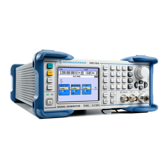
® Preparing for Use R&S SMC100A Front Panel Tour 2 Preparing for Use The following topics help you to get familiar with the instrument and perform the first steps: ● Front Panel Tour ● Rear Panel Tour ● Putting into Operation This section explains the control elements and connectors of the Signal Generator R&S SMC with the aid of the front and rear views and describes how to put the instru- ment into operation. -
Page 25: Utility Keys
® Preparing for Use R&S SMC100A Front Panel Tour Figure 2-1: Front panel view 2.1.1 Utility Keys The keys to the left of the display cause the R&S SMC to return to a definite instrument state and provide information on the instrument and assistance. For more information refer to chapter "Instrument Settings"... -
Page 26: Display
® Preparing for Use R&S SMC100A Front Panel Tour The standby LEDs and the ON/STANDBY key are located in the bottom left corner of the front panel. The ON/STANDBY key toggles the instrument between standby and ready state (indi- cated by the standby LEDs). The standby LEDs indicate the instrument states as follow: ●... -
Page 27: Display Keys
® Preparing for Use R&S SMC100A Front Panel Tour These keys provide direct access to the settings in the header of the instrument for fast setting the RF signal. For more information refer to chapter "Instrument Functions" in the Operating Manual. FREQ Activates frequency entry. -
Page 28: Keypad For Data Entry
® Preparing for Use R&S SMC100A Front Panel Tour RF ON/OFF Switches the RF signal on and off. "RF OFF" is displayed in the header next to the "Frequency" field. 2.1.5 Keypad for data entry The keys in the data entry keypad are used to enter alphanumeric data and units. Data entry keys are only enabled while the cursor is placed on a data input field in a dialog. -
Page 29: Rotary Knob And Navigation Keys
® Preparing for Use R&S SMC100A Front Panel Tour 2.1.6 Rotary Knob and Navigation Keys The rotary knob and the arrow keys are alternative control elements for data variation and navigation in the graphical user interface. ROTARY KNOB The rotary knob has several functions: ●... -
Page 30: Rear Panel Tour
® Preparing for Use R&S SMC100A Rear Panel Tour Output for internal LF modulation generator signal. See also data sheet and Operating Manual, section "LF Generator and LF Output". RF 50 Ohm Output for RF signal. NOTICE! Maximum Input Levels. Do not overload the RF output. The instrument is equipped with a reverse power protection that prevents the RF out- put against back feed, see section "Reverse Power Protection"... -
Page 31: Description Of The Connectors
® Preparing for Use R&S SMC100A Rear Panel Tour Figure 2-2: Rear panel view 2.2.1 Description of the Connectors AC SUPPLY AND POWER SWITCH When the R&S SMC is connected to the AC supply, it automatically sets itself to the correct range for the applied voltage (range: see type label). - Page 32 ® Preparing for Use R&S SMC100A Rear Panel Tour IEC 625/IEEE 488 IEC-bus (IEEE 488) interface for remote control of the instrument. See also Chapter A.1, "GPIB Bus Interface", on page 72 and chapter "Remote Con- trol Basics" in the Operating Manual. Note: In order to avoid electromagnetic interference (EMI) caused by open lines, always terminate any connected IEC-bus cable with an instrument or a controller.
-
Page 33: Putting Into Operation
® Preparing for Use R&S SMC100A Putting into Operation USB CONNECTORS TYPE A USB (universal serial bus) interfaces of type A (host USB). ● Connection of peripherals such as mouse, keyboard, etc. ● Connection of memory stick for file transmission ●... -
Page 34: Emi Suppression
® Preparing for Use R&S SMC100A Putting into Operation Risk of electrostatic discharge (ESD) Electrostatic discharge (ESD) can damage the electronic components of the instrument and the device under test (DUT). ESD is most likely to occur when you connect or dis- connect a DUT or test fixture to the instrument's test ports. -
Page 35: Placing Or Mounting The Instrument
® Preparing for Use R&S SMC100A Putting into Operation 2. Carefully remove the pads from the instrument handles at the front. 3. Pull off the corrugated cardboard cover that protects the rear of the instrument. 4. Carefully unthread the corrugated cardboard cover at the front that protects the instrument handles and remove it. -
Page 36: Connecting The Instrument To The Ac Supply
® Preparing for Use R&S SMC100A Putting into Operation Risk of injury and instrument damage if stacking instruments A stack of instruments may tilt over and cause injury. Furthermore, the instruments at the bottom of the stack may be damaged due to the load imposed by the instruments on top. -
Page 37: Starting The Instrument
® Preparing for Use R&S SMC100A Putting into Operation ► Connect the instrument to the AC power source using the AC power cable deliv- ered with the instrument. Note: The instrument is in compliance with safety class EN61010-1. Connect the instrument only to a socket with earthing contact. 2.3.5 Starting the Instrument Switching off the AC power You can leave the AC power on permanently to preserve your last instrument settings. -
Page 38: Function Check
® Preparing for Use R&S SMC100A Putting into Operation Once the startup procedure has been terminated, the block diagram opened in the pre- vious session is displayed and the instrument is ready for operation. Use the PRESET key to return the instrument to its definite reset/preset state, if the current setup is not anymore relevant. -
Page 39: Shutting Down The Instrument
® Preparing for Use R&S SMC100A Putting into Operation ● Preset the instrument to its factory settings The instrument can also be forced to load its default factory settings. To access the corresponding dialog box, press the SETUP key and select the "Factory Preset". For more information and an overview of the settings affected by the factory preset function, see section "Factory Preset"... -
Page 40: Power Fuses
® Preparing for Use R&S SMC100A Connecting External Accessories Risk of losing data If you switch off the running instrument using the rear panel switch or by disconnecting the power cord, the instrument loses its current settings. Furthermore, program data may be lost. -
Page 41: Linux Operating System
® Preparing for Use R&S SMC100A Linux Operating System The following list shows various USB devices that can be useful: ● Memory stick for easy transfer of data to/from a computer (for example firmware updates) ● CD-ROM drives for easy installation of firmware applications ●... - Page 42 ® Preparing for Use R&S SMC100A Linux Operating System Risk of causing instrument unusability The instrument is equipped with the Linux operating system. Additional software can therefore be installed on the instrument. The use and installation of additional software may impair instrument function. Thus, run only programs that Rohde & Schwarz has tested for compatibility with the instrument software.
-
Page 43: Setting Up A Network (Lan) Connection
® Preparing for Use R&S SMC100A Setting Up a Network (LAN) Connection Screen saver A screen saver can be activated in the R&S SMC. When active, the display is shut off when no entries via front panel, external mouse or external keyboard are made for a period of time. -
Page 44: Assigning The Ip Address
® Preparing for Use R&S SMC100A Setting Up a Network (LAN) Connection To set up a network (LAN) connection Risk of network failure Before connecting the instrument to the network or configuring the network, consult your network administrator. Errors may affect the entire network. ►... -
Page 45: Using Computer Names
® Preparing for Use R&S SMC100A Setting Up a Network (LAN) Connection Risk of network errors! Connection errors can affect the entire network. If your network does not support DHCP, or if you choose to disable dynamic TCP/IP configuration, you must assign valid address information before connecting the instru- ment to the LAN. -
Page 46: Remote Access Via An External Controller
® Preparing for Use R&S SMC100A Remote Access via an External Controller Each instrument is delivered with an assigned computer name, but this name can be changed. The default instrument name is a non-case-sensitive string that follows the syntax rs<instrument><serial number>. The serial number can be found on the rear panel of the instrument. -
Page 47: Using A Web Browser For Remote Access
® Preparing for Use R&S SMC100A Remote Access via an External Controller Table 2-1: Remote access via an external computer Remote access via Installation of the additional application connec- on the on the remote tion instrument computer Any web browser required Java Runtime must be installed and... -
Page 48: Remote Access Via A Vnc Client Software
® Preparing for Use R&S SMC100A Remote Access via an External Controller To remote access the instrument via a web browser: 1. Connect the instrument and the remote computer to a LAN, see Chapter 2.6.1, "Connecting the Instrument to the Network", on page 28. - Page 49 ® Preparing for Use R&S SMC100A Remote Access via an External Controller Risk of Unauthorized Access If the VNC service is enabled on the instrument, any user in the network who knows the computer name and password can access it. Disable the VNC service on the instrument to prevent unauthorized access.
- Page 50 ® Preparing for Use R&S SMC100A Remote Access via an External Controller a) Select installation of all components. b) In the "Additional Task Panel", enable all entries. A successful installation is indicated by a message. At the same time a warning is displayed stating that a password must be set. 4.
- Page 51 ® Preparing for Use R&S SMC100A Remote Access via an External Controller 5. Enter a password with a length of at least five digits. This password is used on the remote computer to access the instrument. Other settings may be changed according to the user-specific security requirements. After the installation the Ultr@VNC program is automatically started together with the operating system.
- Page 52 ® Preparing for Use R&S SMC100A Remote Access via an External Controller A dialog is opened and the password for the remote VNC connection is requested. 3. Enter the password as defined in the "Default Local System Properties" panel of the Ultr@VNC program and select "Log On".
- Page 53 ® Preparing for Use R&S SMC100A Remote Access via an External Controller Terminating VNC Connection The remote access via VNC connection can be terminated either on the R&S SMC or on the external PC. Terminating the connection does not disable it. It can be estab- lished again any time.
-
Page 54: Getting Started
® Getting Started R&S SMC100A Brief Introduction to the Instrument's Concept 3 Getting Started This section helps you to get familiar with the R&S SMC. It provides an introduction to the general concept of the instrument with a sample of the possible application fields, and a description of the main blocks in the signal generation flow. - Page 55 ® Getting Started R&S SMC100A Brief Introduction to the Instrument's Concept Figure 3-1: Block diagram of a fully equipped R&S SMC With the rotary knob, you can navigate in the block diagram and the dialogs, and oper- ate the instrument with one hand. The cursor is moved line by line through the block diagram or dialog.
-
Page 56: Application Field Of The Instrument
® Getting Started R&S SMC100A Application Field of the Instrument Tip: For remote control over LAN or USB, you can use the R&S VISA (Virtual Instru- ment Software Architecture) library provided for download at the Rohde & Schwarz website http://www.rohde-schwarz.com/rsvisa. This way of operation and the instructions how to set up a connection for remote con- trol are described in the operating manual, chapter "Remote Control Basics". -
Page 57: Description Of Individual Diagram Blocks
® Getting Started R&S SMC100A Description of Individual Diagram Blocks ● remote control via USB, LAN and IEC Bus Note: For faster operation by remote control the instrument can be equipped with an IEC bus interface (option R&S SMC-K4). 3.3 Description of Individual Diagram Blocks The signal path of the instrument is configured by installing a frequency option that comprises all required modules. -
Page 58: Example Of Setup
® Getting Started R&S SMC100A Example of Setup The internal modulation sources are configured in the "Mod Gen" block. External amplitude, frequency or phase modulation signals can be fed in at the input connector MOD EXT at the front of the instrument. An external pulse signal is fed in via the BNC connector PULSE EXT at the rear of the instrument. - Page 59 ® Getting Started R&S SMC100A Example of Setup 2. Select and activate AM modulation a) Turn the rotary knob and select the "Modulation" block. b) Press the rotary knob to open the dialog where the modulation can be selected. The "Amplitude Mod..." menu is the first menu and is highlighted per default. c) Turn the rotary knob and highlight "Amplitude Mod...".
- Page 60 ® Getting Started R&S SMC100A Example of Setup To indicate the active state, the "Modulation" block is displayed in blue. The "RF" is not yet active, which means that no RF signal is output. 3. Set frequency and level and activate RF signal a) Press the FREQ key to activate the editing mode for frequency entry.
- Page 61 ® Getting Started R&S SMC100A Example of Setup a) Turn the rotary knob and select the "RF" block. b) Press the rotary knob to open the dialog where the RF frequency sweep can be selected. c) Turn the rotary knob and highlight "RF Frequency Sweep...". Press the rotary knob to open the "RF Frequency Sweep"...
- Page 62 ® Getting Started R&S SMC100A Example of Setup 3. Activate RF signal. a) Turn the rotary knob to select the "RF" block. b) Press the RF ON/OFF key to activate the "RF" signal output. To indicate the active state, the RF block is displayed in blue. An RF signal with the default frequency and level settings is output, i.e.
-
Page 63: Manual Operation
® Manual Operation R&S SMC100A Key Features 4 Manual Operation The R&S SMC can be operated intuitively either via the interactive block diagram or via a menu tree. All menus are in the form of windows that can be operated in the same way. - Page 64 ® Manual Operation R&S SMC100A Key Features a blue frame can be directly switched on and off by means of the TOGGLE ON/OFF (CTRL+T) key. The menus of the highlighted function blocks can be called by pressing the ENTER key. –...
- Page 65 ® Manual Operation R&S SMC100A Key Features ● Pressing the rotary knob activates the selected entry field. Depending on the parameter, the submenu is called, the numeric value varied, the list entry selected or the check box activated or deactivated. ●...
-
Page 66: Display
® Manual Operation R&S SMC100A Display background information on the message and indicate operating steps that may be required. All messages are explained in the online help which can be called with the HELP (F1) key. 4.2 Display The display shows the current signal generator state and offers graphical elements for direct operation. -
Page 67: Status Information And Messages
® Manual Operation R&S SMC100A Display The values displayed in the "Freq" and "Level" fields include a set offset or multiplier factor. See also "RF Frequency and Phase" and "RF Level" in the Operating Manual. The frequency and level indication can be enlarged so that it covers the complete dis- play of the R&S SMC by using the DIAGR key. -
Page 68: Permanent Messages
® Manual Operation R&S SMC100A Display These messages can be read from remote using SYST:ERR? or SYST:ERR:ALL?. 4.2.2.4 Permanent Messages Permanent messages are displayed if an error occurs that impairs further instrument operation, e.g. a hardware fault. The error signalled by a permanent message must be eliminated before correct instrument operation can be ensured. -
Page 69: Block Diagram
® Manual Operation R&S SMC100A Display This button is available only if the history of the messages is displayed. History Calls the list of all messages that have occurred since instrument switch-on. The most recent messages are displayed at the top of the list. When the button is pressed again, the list of current messages is displayed. -
Page 70: Signal Flow And Input/Output Symbols In The Block Diagram
® Manual Operation R&S SMC100A Display 4.2.4.2 Signal Flow and Input/Output Symbols in the Block Diagram The input/output symbols in the block diagram show the currently used inputs and out- puts of the signal generator. Unused inputs and outputs are not shown. The lines indi- cate the signal flow. -
Page 71: Accessing Dialogs
® Manual Operation R&S SMC100A Accessing Dialogs configuration. If setting is not permitted with the specific configuration selected, the respective item is disabled and displayed in gray and the entry or selection field cannot be accessed. 4.3 Accessing Dialogs The MENU (CTRL+M) key opens the complete menu tree. Selecting a functional block and pressing the ENTER key opens the menu associated with this block. -
Page 72: Setting Parameters
® Manual Operation R&S SMC100A Setting Parameters 4.4 Setting Parameters The R&S SMC offers several and sometimes alternative possibilities for setting param- eters. Operation is possible from the front panel, with the aid of a mouse and/or from a PC keyboard. The examples whitin this description focus on the operation from the front panel. -
Page 73: Selecting A Control Element
® Manual Operation R&S SMC100A Setting Parameters Moving the cursor on the display ► To move the cursor, use one of the following alternative methods: a) Use the rotary knob or the arrow keys. b) Use the "Winbar" key in the key emulation to toggle between the active dialogs. c) Use the ESC key. -
Page 74: Entering A Value
® Manual Operation R&S SMC100A Setting Parameters ● Press the TOGGLE ON OFF (CTRL+T) key. Colour and label of a button change, the check box is ticked or the tick is removed. 4.4.4 Entering a Value Numeric and alphanumeric values can be edited in the entry fields. In the editing mode, cursors of different colour are used. -
Page 75: Working With Units
® Manual Operation R&S SMC100A Setting Parameters The value at the cursor position is varied. 3. To vary the selected value, use the UP/DOWN arrow key or turn the rotary knob. The value is increased or decreased. Entering a new alphanumerical value 1. -
Page 76: Selecting A Value From A List
® Manual Operation R&S SMC100A Setting Parameters 2. Select a "Unit" in the selection field next to the parameter value. Press the ENTER key. The unit displayed in the entry field next to the value is assigned. Changing a unit To subsequently change a unit, i.e. -
Page 77: Restoring The Previous Value
® Manual Operation R&S SMC100A Setting Parameters Confirming settings ► To confirm the settings, press the rotary knob or one of the UNIT keys (see also Chapter 4.4.5, "Working with Units ", on page 60) . Note: Variations by means of the rotary knob are immediately set. Confirming multiple values In some cases, like for instance when editing data in a user correction table, it is useful first to enter few values and to confirm them together. -
Page 78: Editors
® Manual Operation R&S SMC100A Editors 2. Confirm with "OK" to abort the changes. Select "Cancel" to return to the dialog. The previous selected settings are dis- played. Restoring values after an extended calculation has been started Calculation and setting might require different period of time. Many settings are made without noticeable calculation times;... - Page 79 ® Manual Operation R&S SMC100A Editors If no list has been selected, a blank list of only one row is displayed. 2. Press the LEFT/RIGHT arrow keys to change between the colums. Use the UP/DOWN arrow keys to mark a row. 3.
-
Page 80: How To Use The Help System
® Manual Operation R&S SMC100A How to Use the Help System 4.6 How to Use the Help System The R&S SMC is equipped with a context-sensitive help function. A help page is avail- able for each parameter and can be called any time during instrument operation. Calling context-sensitive and general help ►... -
Page 81: File Management
® Manual Operation R&S SMC100A File Management 2. Enter the first characters of the topic you are interested in. The entries starting with these characters are displayed. 3. Press the ENTER key to change the focus. 4. Use the UP/DOWN keys to navigate and select the suitable keyword. 5. -
Page 82: File Select Dialog
® Manual Operation R&S SMC100A File Management For more information, refer to: ● Chapter 4.8, "Legend of Front-Panel Controls", on page 70 for an overview of key functions and a cross-reference between the front panel keys and the keyboard shortcuts ●... -
Page 83: File Manager
® Manual Operation R&S SMC100A File Management The available drives and directories and the files of the selected directory are dis- played. The currently selected path is displayed above the window. Only the relevant files without file extensions are displayed. If the area is opened several times, the path last selected is displayed. -
Page 84: Extensions For User Files
® Manual Operation R&S SMC100A File Management Use the "File Type" to select a file type from the list. This can be used to process either all files (all files (*) selection) or a specific selection of files. See Chapter 4.7.2.1, "Extensions for User Files", on page 69 for an overview of the supported file exten-... -
Page 85: Legend Of Front-Panel Controls
® Manual Operation R&S SMC100A Legend of Front-Panel Controls Table 4-1: List of the automatically assigned file extensions in the instrument Function List type Contents File suffix Instrument State Settings Instrument settings *.savrcltxt "User Correction" List User-defined level correction values *.uco Export Data *.txt or *.csv... -
Page 86: Front Panel Key Emulation
® Manual Operation R&S SMC100A Legend of Front-Panel Controls Front-panel key Key of PC keyboard Function FREQ CTRL+ F Activates the frequency entry. G/n / dBuV ALT + F9 Selects the unit Giga/Nano, dBuV for the RF level and dBu for the LF level. HELP Opens/closes context-sensitive help. -
Page 87: Annex
® Hardware Interfaces R&S SMC100A GPIB Bus Interface Annex A Hardware Interfaces This section covers hardware related topics, like pin assignment of the GPIB bus inter- face. The remote control interfaces are described in detailes in the Operating Manual, sec- tion "Remote Control Basics". - Page 88 ® Hardware Interfaces R&S SMC100A GPIB Bus Interface IFC (Interface Clear): active LOW resets the interfaces of the instruments connec- ted to the default setting. ATN (Attention): active LOW signals the transmission of interface messages, inac- tive HIGH signals the transmission of device messages. SRQ (Service Request): active LOW enables the connected device to send a ser- vice request to the controller.
-
Page 89: Index
® Index R&S SMC100A Index Abort button ...............63 Failure Abort calculation ..............63 Network connection ............ 29 AC supply ................. 16 Features of R&S SMC ............41 Access denied ..............55 Frequency display ............. 51 Application cards ..............8 Front panel key emulation ..........71 Application notes .............. - Page 90 ® Index R&S SMC100A Manual Remote Control ............ 31 VNC connection ..............33 Menu structure Access denied ............55 Header ................ 55 Warnings ................53 Menu area ..............55 White papers ............... 8 Mod Gen block ..............42 Navigation keys ..............14 NDAC ................
Need help?
Do you have a question about the SMC100AP31 and is the answer not in the manual?
Questions and answers