
Related Manuals for SystemAir TFC-P Roof fan EC


Summary of Contents for SystemAir TFC-P Roof fan EC
- Page 1 Installation, Operation and Maintenance instruction TFC-P Roof fan EC TFC-S Roof fan EC...
-
Page 2: Table Of Contents
Table of content 1 Introduction ............1 10.1 To disassemble and discard the parts of the product............ 14 Product description ........1 Intended use ..........1 11 Warranty ............15 Document description........1 12 Technical data ........... 15 Product overview......... 1 12.1 Technical data overview ...... -
Page 3: Introduction
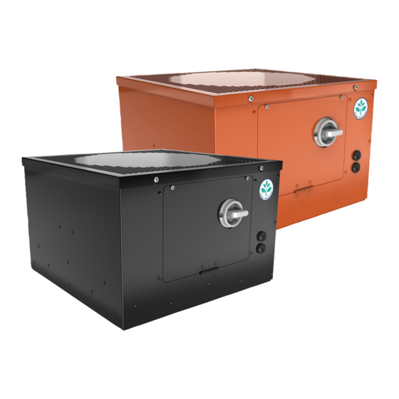
The procedures must be done by approved personnel only. Speak to Systemair for more information on how to install the product in different installation locations. Product overview A. TFC-P 355 — 560... -
Page 4: Name Plate
• The product is used without motor protection. The data on the name plate applies to “standard air” that is specified in the standard ISO5801. Use a mobile device to scan the scannable code and go to the Systemair documentation portal for more documentation and document translations. -
Page 5: Safety
• Always use spare parts from Systemair. • Sound levels exceeding 70 dB(A) may occur depending on model and size. Visit www.systemair.com for more de- tailed information about your product. • The product is not to be used by persons, including chil-... -
Page 6: Transportation And Storage
– To decrease vibrations transmitted from the product to • Do not move the product by the cables, terminal box, fan the duct system, Systemair recommends to install vi- impeller, protection grille, inlet cone or silencer. bration dampers, fast clamps or flexible connections. - Page 7 Install the fan so that unwanted vibrations are not trans- mitted to duct systems or roof beams. Note: Systemair recommends to install the product together with a roof curb. The roof curb is available as an accessory.
-
Page 8: To Operate The Pressure Controller
Note: gland on the roof curb. Full instruction manual for PCA-2 1000 D2 controller is available at www.systemair.com. 4.2.3 To set up the controller for Note: The pressure controller is supplied from the factory pre- pared for VAV. -
Page 9: To Change From Vav Control To Cav Control
Press “Down” to go to “Metrics units” and press “P” to 4.2.4 To change from VAV control choose “1: metric unit” (The factory setting, measures in to CAV control Pa, m3/h, K-factor). Loosen the screws on the casing and the electrical cabi- Press “Down”... -
Page 10: To Use Modbus Communication
To set up MODBUS communication, refer to the MODBUS • Setpoint 2 — The pressure setpoint during a secon- communication tag list available at www.systemair.com. dary operation mode. The factory setting is 50 % of the measuring range. Setpoint 2 is active when there is a connection between input 1 and 2. -
Page 11: Electrical Connection
The commissioning report is found at www.systemair.com. To connect the product to the power supply To do before the •... -
Page 12: Operation
EC motors must be set to ON/OFF via the control input. To stop the product via mains supply decreases the life time of the motor. Systemair recommends to install external speed controller for easy access to control the input signal. -
Page 13: To Clean The Product
• When you send an order for spare parts, include the serial number of the product. The serial number is found on the name plate. Troubleshooting Note: If you cannot find a solution to your problem in this section, speak to Systemair technical support. - Page 14 Problem Cause Solution The fan impeller is not correctly Speak to Systemair technical support. balanced. There is dirt on the fan impeller. Clean the fan impeller carefully. Refer 8.2 To clean the product page The fan impeller has damages or Speak to Systemair technical support.
- Page 15 This is not applicable for EC motors or 3–phase AC motors. There is blockage in the motor. Speak to Systemair technical support. Defective motor winding. If it is possible, measure the resistance to do a check of the motor winding.
-
Page 16: Disposal
Disposal 10.1 To disassemble and discard the parts of the product The product follows the WEEE directive. This symbol on the product or the packaging of the product shows that this Disconnect and disassemble the product in the opposite product is not domestic waste. The product must be recycled sequence of electrical connection and installation. -
Page 17: Warranty
12.1 Technical data overview Maximum temperature of transported air, °C Sound pressure, dB Refer to the data sheet in the online catalogue at www.systemair.com. Corrosion class IP class Voltage, current, frequency, enclosure Refer to the name plate. Refer to 1.5 Name plate page 2 for more information. -
Page 18: Wiring Diagrams
ØG TFC 450 TFC 500 TFC 560 12.3 Wiring diagrams Abbreviation in wiring diagram Cable colour Yellow Blue White Green Brown Black Grey Green/Yellow 12.3.1 Wiring diagrams for TFC-P fans TFC-P fans 1–phase 230 V TFC-P 225 TFC-P 280 4 5 6 7 24V 230V N/L2 10..24VDC... - Page 19 Safety switch Aux. contact/Sign relay 24 V DC 0-10 V out 0-10 V out Digital input Digital input Temperature Modbus slave 10. Transformer 11. Pressure controller PCA-2 1000 D2 12. ON/OFF 13. PTC/PT 1000 14. Motor 15. 230 V 1~ TFC-P fans 1–phase 230 V TFC-P 355...
-
Page 20: Wiring Diagrams For Tfc-S Fans
TFC-P fans 3–phase 400 V TFC-P 500 TFC-P 560 230V N/L2 TF TF RSA RSB 10..24VDC Safety switch Aux. contact/Signal relay 24 V DC 0–10 V out 0–10 V out Digital input Digital input Temperature Modbus slave 10. Transformer 11. Connection box 12. - Page 21 TFC-S fans 1–phase 230 V TFC-S 225 TFC-S 280 Connection box 0–10 V DC Ext. Time (1 = min.) Safety switch Motor 230 V 1~ TFC-S fans 1–phase 230 V TFC-S 355 TFC-S 450 Connection box 0–10 V DC Ext. Time (1 = min.) Alarm Safety switch...
-
Page 22: Pressure Controller Connection Overview
TFC-S fans 3–phase 400 V TFC-S 500 TFC-S 560 Connection box 0–10 V DC Ext. Time (1 = min.) Alarm Safety switch ON/OFF Motor 230 V 1~ 12.3.3 Pressure controller connection overview Pressure controller PCA–2 1000... -
Page 23: Wiring Diagrams For Speed Controllers For Ec Motors
Signal relay (terminals: 13, 14) Supply voltage (terminals: U , GND) Output signal 0...10 V (terminals: A, GND) Cable gland M16 “Minus” — connection in areas with lower pressure “Plus” + connection in areas with higher pressure Digital input D1 (terminals: 1, 2) Input outdoor temperature sensor (terminals: TF, TF) MODBUS interface (terminals: GND, A, B, ID1, ID2 and jumper J1) 12.3.4... - Page 24 MTV–1/10 MTV 1/010 1/IN Vac 230V AC 2/IN Vac +10V 4/Out+ 0...10V 5/Out- S-5EC/FRQ MTP 10 +10V 0...10V EC-Vent optional IN/RPM TACH IN/10V +10V OUT/PWN 0...10V/PWM...
-
Page 25: Wiring Diagrams For On/Off Controls For Ec Motors
12.3.5 Wiring diagrams for ON/OFF controls for EC motors CO2RT-R(-D) Supply +10V 24V AC Neutral 0...10V Common Relay NO Relay NC Din1 IR24–P +10V 24V AC or DC Neutral 0...10V Common Relay NO Relay NC Din1 12.3.6 Wiring diagrams for demand control for EC motors EC Basic EC Basic-T for temperature control EC-Basic... - Page 26 EC-Vent Demand control for up to 5 external sensors, 2 fans, damp- ers, heaters and coolers. The EC vent system has 2 units. The control board (CB) and the room unit (RU). Connect the fan to the control board and optional IN/RPM TACH...
- Page 27 Control Board (CB) ALARM FAN OUT3 OUT2 OUT1 DEBUG PT1000 +24VDC PT1000 Y +0-10V PT1000 Br + 24VDC N out N in L out L in Mains supply, 230 V 1~AC (10 A) Analogue sensor (for example, pressure sensor) C. Analogue sensor (for example, pressure sensor type PT1000) D.
-
Page 28: Accessory Overview
0 = Setpoint 1 1 = Setpoint 2 Mains supply 10..24 V DC Output 0..10 V Pressure connections Voltage input for switch on Setpoint 1/Setpoint 2 Accessory overview Note: For more information about accessories, refer to www.systemair.com or speak to Systemair technical support. - Page 29 TFC-P/TFC-S fan Roof curb TG Note: For more information about accessories, refer to www.systemair.com or speak to Systemair technical support.
-
Page 30: Eu Declaration Of Conformity
EU Declaration of Conformity We, the manufacturer Manufacturer Systemair Sverige AB Address Industrivägen 3 739 30 Skinnskatteberg Sweden declare under our sole responsibility that the products Type/Model TFC-P, TFC-S Identification Serial numbers dating from 2022 and onwards fulfils the relevant provisions of following directives and... -
Page 31: Declaration Of Conformity
UK Declaration of Conformity We, the manufacturer Manufacturer Systemair Sverige AB Address Industrivägen 3 SE-73930 Skinskatteberg Sweden declare under our sole responsibility that the products Type/Model TFC-P, TFC-S Identification Serial numbers dating from 2022 and onwards fulfils the relevant provisions of following directives and... - Page 32 © Copyright Systemair AB All rights reserved Systemair AB reserves the rights to alter their products without notice. This also applies to products already ordered, as long as it does not affect the previously agreed specifications. Original instructions 2022-05-30...
Need help?
Do you have a question about the TFC-P Roof fan EC and is the answer not in the manual?
Questions and answers