Image Engineering GEOCAL User Manual
Hide thumbs
Also See for GEOCAL:
- User manual (15 pages) ,
- User manual (19 pages) ,
- User manual (48 pages)

Related Manuals for Image Engineering GEOCAL


Summary of Contents for Image Engineering GEOCAL
- Page 1 GEOCAL / GEOCAL XL User Manual December 22, 2023 Image Engineering GmbH & Co. KG · Im Gleisdreieck 5 · 50169 Kerpen · Germany T +49 2273 99 99 1-0 · F +49 2273 99 99 1-10 · www.image-engineering.com...
-
Page 2: Table Of Contents
3.3.1 Camera position and suitable lenses ..............7 3.3.2 Exposure ......................8 DIFFERENCES BETWEEN GEOCAL AND GEOCAL XL ..........9 4.1 Why a larger version of the GEOCAL? ..............9 OPERATING INSTRUCTIONS SOFTWARE ............... 10 5.1 Installing GEOCAL software .................. 10 5.2 Configuration file (XML format) ................ - Page 3 5.11 Quit ........................15 5.12 TRADEMARK AND COPYRIGHT ................. 15 ADDITIONAL INFORMATION ..................16 6.1 Disposal instructions ..................... 16 6.2 Power circuit modification for production line use ........... 16 TECHNICAL DATA SHEET ..................16 Image Engineering Seite 3 von 16...
-
Page 4: Introduction
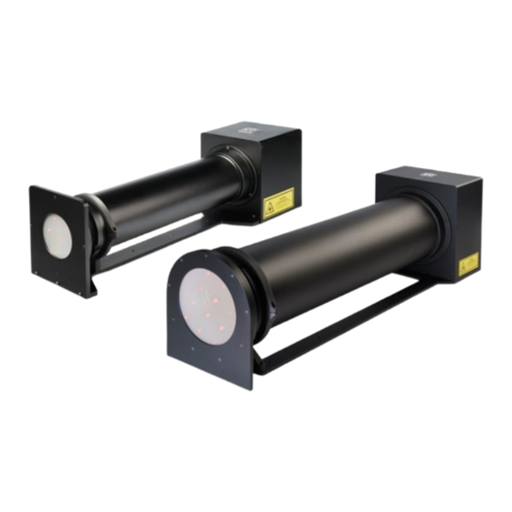
GEOCAL/GEOCAL XL consists of an illuminating hardware device and software for the geometric calibration of camera systems. The GEOCAL software is used for calculating the calibration parameters f rom a single image taken with a camera system of the point grid generated by the GEOCAL hardware device. -
Page 5: Getting Started
The power socket and the main power switch are located on the back side of the device next to the USB type B socket. Connect GEOCAL/GEOCAL XL to a power outlet and switch it on. Please note that the blue LED next to the power switch indicates that the power line is active and that GEOCAL is ready f or operation. -
Page 6: Operating Instructions Hardware
The autof ocus must be turned of f . Since GEOCAL / GEOCAL XL uses a collimated light beam virtually originating from infinity, the appropriate f ocus distance will be near inf inity. Using manual f ocus, ensure the camera is f ocused on the light points. -
Page 7: Camera Position And Suitable Lenses
The camera rotation to the DOE is part of the calibration and is determined during the process and reported as part of the result. The lens's f ront element must not be larger than 77 mm in diameter for GEOCAL or 155 mm for GEOCAL XL to capture the point grid in f ull f ormat. -
Page 8: Exposure
Do not change the camera's orientation between images because the points would no longer be aligned to one another through multiple images. Image Engineering Seite 8 von 16... -
Page 9: Differences Between Geocal And Geocal Xl
4 DIFFERENCES BETWEEN GEOCAL AND GEOCAL XL The key difference between GEOCAL XL and the standard GEOCAL is the physical size of the dif f ractive optical element (DOE) that generates the point grid. While the standard GEOCAL has a usable diameter of 77 mm, the GEOCAL XL provides a f unctional diameter of 155 mm. -
Page 10: Operating Instructions Software
5 OPERATING INSTRUCTIONS SOFTWARE The GEOCAL sof tware allows you to calibrate your camera system in a matter of seconds. The results can be saved as CSV or XML f iles. 5.1 Installing GEOCAL software • Execute the GEOCAL installer (GEOCAL_Vx.x.x.exe, 64-bit) and f ollow the instructions. -
Page 11: Loading Images For Analysis
To f amiliarize yourself with the various models and the interactions of the parameters in the conf iguration f iles, you can use the def ault conf igurations given f or each model and execute the GEOCAL sof tware on the simulated images. -
Page 12: Image Analysis
The four remaining ROIs must be positioned on the points closest to the 0 diffraction order, i.e., the one above, below, and to the left and right. These four ROIs may also only contain one point. Furthermore, Image Engineering Seite 12 von 16... -
Page 13: Saving Results
Then click File → Save result → Save XML or Save CSV → navigate to the desired location → click Save If you selected multiple images, all results would be saved in one CSV or XML f ile. Image Engineering Seite 13 von 16... -
Page 14: Export Grids
Two dif ferent histograms are shown. The f irst histogram contains the successf ully detected dif f raction points dependent on the radius. The values start at zero (principal point) and run along the image diagonal to the image corner (one). Image Engineering Seite 14 von 16... -
Page 15: Logging
Click File (Quit (Ctrl+q) to exit the software or close the window. 5.12 TRADEMARK AND COPYRIGHT Trademarks Windows is a registered trademark of Microsof t Corp. Copyright Information See separate Terms and Conditions document. Image Engineering Seite 15 von 16... -
Page 16: Additional Information
6.2 Power circuit modification for production line use If you plan to use your GEOCAL/GEOCAL XL on a production line, we offer the option of modif ying the unit to eliminate the need to press the switch to turn it on and off. After the modification, moving the switch to the "ON"...
Need help?
Do you have a question about the GEOCAL and is the answer not in the manual?
Questions and answers