Image Engineering GEOCAL User Manual
Hide thumbs
Also See for GEOCAL:
- User manual (19 pages) ,
- User manual (16 pages) ,
- User manual (48 pages)

Related Manuals for Image Engineering GEOCAL


Summary of Contents for Image Engineering GEOCAL
- Page 1 GEOCAL User Manual 1. December 2020 Image Engineering GmbH & Co. KG · Im Gleisdreieck 5 . 50169 Kerpen . Germany T +49 2234 2273 99 99 1-0 . F +49 2234 2273 99 99 1-10 . www.image-engineering.com...
-
Page 2: Table Of Contents
Camera settings ......................5 3.3.1 Camera position and suitable lenses ..............6 3.3.2 Exposure ......................7 OPERATING INSTRUCTIONS SOFTWARE ..............8 Installing GEOCAL software ..................8 Configuration File (XML) ................... 8 Loading images for analysis ..................10 Image analysis ......................10 Saving results ......................12 Logging ........................12... -
Page 3: Introduction
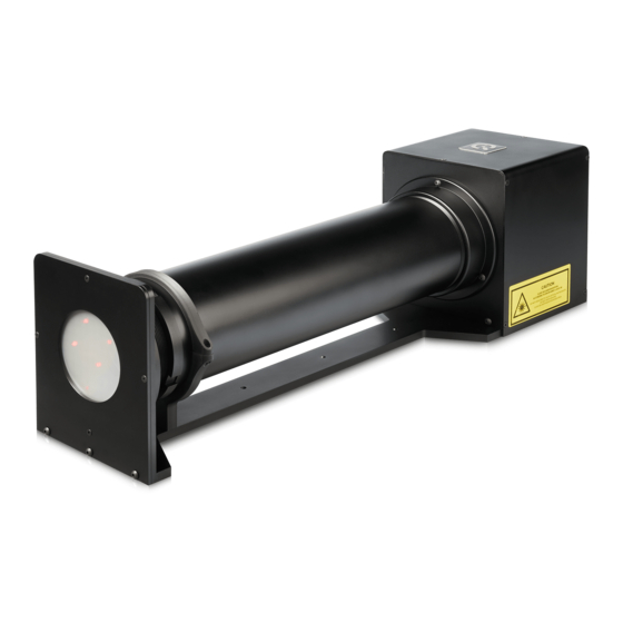
GEOCAL consists of an illuminating hardware device and software for geometric calibration of camera systems. The GEOCAL software is used for calculating the calibration parameters from a single image taken with a camera system of the point grid generated by the GEOCAL hardware device. -
Page 4: Getting Started
• The power socket is located on the left-hand side of the device next to the USB type B socket. The main power switch is located on the right-hand side. Connect GEOCAL to a power outlet and switch it on. -
Page 5: Operating Instructions Hardware
Auto focus must be turned off. Since GEOCAL uses a collimated light beam virtually originating from infinity, the appropriate focus distance will be near infinity. Using manual focus, make sure that the camera is focused on the light points. -
Page 6: Camera Position And Suitable Lenses
Bad alignment (0 order far off center) The top side of Geocal and the top side of the camera must have the same orientation. A rotation of the camera around the optical axis of approx. +/- 2° will be tolerable. -
Page 7: Exposure
Do not change the orientation of the camera in between images because the points would be no longer aligned to one another through multiple images. Image Engineering Seite 7 von 15... -
Page 8: Operating Instructions Software
4 OPERATING INSTRUCTIONS SOFTWARE The GEOCAL software enables you to perform a complete calibration of your camera system in a matter of seconds. The results can be saved as CSV or XML files. Installing GEOCAL software • Execute the GEOCAL installer (GEOCAL_Vx.x.x.exe, 64 bit) and follow the instructions. - Page 9 “SetToInvariant” flag back to “false” again. Loading a config file: Click File → Load configuration (ctrl+c) → navigate to the folder containing the file → select the file and click “open”. Image Engineering Seite 9 von 15...
-
Page 10: Loading Images For Analysis
Detection is finished when the progress bar at the bottom of the window (5) reaches 100%. By pressing “Show Detected Grid” next to the progress bar, you can display a visualization of the detected/undetected points. Image Engineering Seite 10 von 15... - Page 11 If needed, you can clear the result table by clicking “clear table”. Under the tab “Distortion curve” you also get a graphical visualization of the determined distortion of the camera (Geometric Distortion vs. Field). Image Engineering Seite 11 von 15...
-
Page 12: Saving Results
To exit the software, click File → Quit (ctrl+q) or simply close the window. TRADEMARK AND COPYRIGHT Trademarks Windows is a registered trademark of Microsoft Corp., Copyright Information See separate Terms and Conditions document. Image Engineering Seite 12 von 15... -
Page 13: Additional Information
5 ADDITIONAL INFORMATION Disposal instructions After the service life of GEOCAL, it must be disposed properly. Electrical and electromechanical components are included in GEOCAL. Observe all national regulations. Make sure that GEOCAL cannot be used by third parties after disposing of it. -
Page 14: Data Sheet
Frequency-stabilized diode laser Light source Wavelength 633 nm Output power 5 mW Laser Class (diode only) Laser Class (GEOCAL) 1M (expanded laser beam) 6.2.3 Software PC with Windows 7 operating system (or higher) System requirements USB port • Load multiple images •... -
Page 15: General Description Hardware
550 mm x 144 mm x 162 mm Operating conditions 0-50°C Requirements on the device under test (DUT) Max. dimensions Max. diameter of the camera lens: 75 mm Usable FoV Approx. 30 – 120° (more extreme values need to be tested) Image Engineering Seite 15 von 15...
Need help?
Do you have a question about the GEOCAL and is the answer not in the manual?
Questions and answers