Table of Contents
Advertisement
Quick Links
Instructions
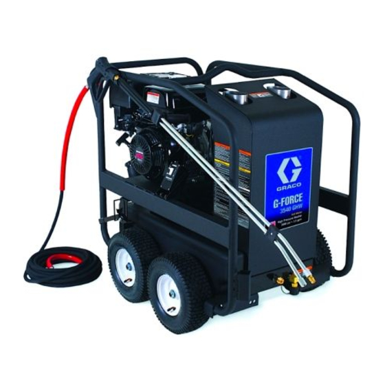
G-Force Hot Water Pressure Washer
IMPORTANT SAFETY INSTRUCTIONS
Read all warnings and instructions in this manual.
SAVE THESE INSTRUCTIONS.
-For high pressure, hot water cleaning-
-For outdoor use only-
Model
Horse Power and
Motor Brand
390 cc Honda
3540GHW
PROVEN QUALITY. LEADING TECHNOLOGY.
Maximum Working
Pressure
PSI
MPa
bar
3500 24.13 241.3
3A0592B
37-1105 051810
Advertisement
Table of Contents

Related Manuals for Graco 3A0592B


Summary of Contents for Graco 3A0592B
- Page 1 Instructions G-Force Hot Water Pressure Washer 3A0592B -For high pressure, hot water cleaning- -For outdoor use only- IMPORTANT SAFETY INSTRUCTIONS Read all warnings and instructions in this manual. SAVE THESE INSTRUCTIONS. Model Horse Power and Maximum Working Motor Brand Pressure 390 cc Honda 3500 24.13 241.3...
-
Page 2: Table Of Contents
Storage & Maintenance instructions ......16 Notes ................36 Technical Data ............. 37 Engine ................16 Graco Standard Warranty ........... 38 THIS SPARK IGNITION SYSTEM COMPLIES WITH CANADIAN ICES-002. CE SYSTÈME D’ALLUMAGE PAR ÈTINCELLE EST CONFORME À LA NORME NMB-002 DU CANADA. -
Page 3: Important
The following warnings are for the setup, use, grounding, maintenance, and repair of this equipment. The exclamation point symbol alerts you to a general warning and the hazard symbols refer to procedure-spe- cific risks. When these symbols appear in the body of this manual, refer back to these Warnings. Product- specific hazard symbols and warnings not covered in this section may appear throughout the body of this manual where applicable. -
Page 4: Fire & Ventilation Precautions
WARNING • Do not direct spray on or into electrical installations of any kind! This includes electrical outlets, light bulbs, fuse boxes, transformers, etc. Severe electrical shock may occur. • Even after you shut off the unit, there is high pressure water left in the pump, hose and gun until you release it by triggering the gun. -
Page 5: Miscellaneous Safety Precautions
WARNING MISCELLANEOUS SAFETY PRECAUTIONS • Never allow children or adolescents to operate this unit. • Read and follow all handling, operations, maintenance and safety instructions listed in this manual and the engine operator’s manual that accompanies this unit, and provide such information to anyone who will be operating this unit. -
Page 6: Component Identification
Component Identification Item Description Item Description 1. Pneumatic Wheels 16. High Pressure Outlet 2. Protective Rollcage 17. Decal-Data Plate 3. Protective Cover 18. Burner Fuel Tank 4. Decal-Warning: Hot Surfaces 19. Decal-Warning/Caution/Operating 5. Center Balanced Lifting Eye 20. Air Shutter Adjusting Arm 6. -
Page 7: Installation & Preparation Instructions
INSTALLATION & PREPARATION INSTRUCTIONS Do not allow the unit to be exposed to rain, snow or Attire freezing temperatures. If any part of the unit becomes frozen, excessive pressure may build up in the unit which could cause it to burst resulting in possible seri- ous injury to the operator or bystanders. -
Page 8: Engine/Burner Fuel Tank
INSTALLATION & PREPARATION The 0° nozzle (RED): This is a blasting nozzle. It deliv- ers a very concentrated stream of water. Be cautious INSTRUCTIONS when using the straight narrow stream. It is not recom- mended for use on painted or wood surfaces, or items Engine/Burner Fuel Tank attached with adhesive backings. -
Page 9: Dual Lance Assembly With Adjustable Pressure
INSTALLATION & PREPARATION Nozzle connection INSTRUCTIONS Be certain the trigger gun is locked in the “OFF” posi- tion. Dual Lance Assembly with Adjustable Pressure This unit features a Dual Lance Assembly with adjust- able pressure which allows the user to select a high or low pressure “fan”... -
Page 10: Water Supply
INSTALLATION & PREPARATION Note: If the mineral content of the water in your area is extremely high, the use of a water softener is recom- INSTRUCTIONS mended to prevent the possibility of excessive scale buildup inside the heat exchanger coil. Water Supply Follow the incoming water requirements listed below: Select a water supply hose which is a quality grade of... -
Page 11: Unloader
See “Fire & Ventilation Precautions” pg. 4. Be sure that all damaged parts are replaced and that the mechanical problems are corrected prior to opera- tion of the unit. If you require service, contact Graco Customer Service. NOTICE Do not overtighten the unloader. -
Page 12: Operating Instructions
OPERATING INSTRUCTIONS NOTICE Be certain the nozzle is not connected to the unit Priming the Pump while priming the pump. Priming allows mineral de- It is essential to prime the pump and flush the unit each posits to be released from the system which would obstruct or damage the nozzle assembly resulting in time the water supply has been disconnected from the unit OR whenever the unit has set for any period of... -
Page 13: Start-Up/Cold Water Operation
OPERATING INSTRUCTIONS 4. At this point, the unit is operating as a cold water pressure washer. Trigger the gun several times and try adjusting the water pressure. Start-up/Cold Water Operation Note: Be certain to lock the trigger gun in the “OFF” position whenever changing the quick connect nozzles. -
Page 14: Start-Up/Hot Water Operation
OPERATING INSTRUCTIONS Start-up/Hot Water Operation The water temperature could become very hot dur- ing hot water operation. Be cautious when adjusting pressure or controlling the trigger gun/dual lance assembly to avoid the possibility of burns. Refer to the “Safety Precautions” pgs. 3-5 before start- ing the unit. -
Page 15: Cleaning With Detergents
OPERATING INSTRUCTIONS Note: This injection system is designed to apply detergents under low pressure only. It will not allow detergent solutions to be introduced into the system Cleaning with Detergents unless the dual lance assembly is set in the low pres- sure detergent mode. -
Page 16: Storage & Maintenance Instructions
STORAGE & MAINTENANCE • Retighten the drain plug when completed. • Dispose of drainage according to environmental INSTRUCTIONS regulations in your area. Burner Air Adjustment Engine The air shutter has been factory preset for proper The engine instructions that accompany your unit detail operation between sea level and 2000 feet elevation at specific procedures for maintenance of the engine. -
Page 17: Winterizing
Gather the following items: according to state EPA laws. • Two 5 gallon containers. Optional Procedure: • One gallon of antifreeze. (Graco® recommends an environmentally safe antifreeze.) 1. Shut the unit and water supply off. • Water supply. 2. Relieve system pressure by pointing the trigger gun in •... -
Page 18: Troubleshooting
Troubleshooting Problem Cause Solution Engine will not start. Various engine problems. Refer to the engine manual accom- panying your unit. Unit components are frozen. Allow to thaw. If any part of the unit becomes frozen; excessive pres- sure may build up in the unit which could cause the unit to burst result- ing in possible serious injury to the operator or bystanders. - Page 19 Troubleshooting Problem Cause Solution Water is leaking under heat ex- Coil drain plug is not installed. Install. changer coil. Safety relief device is relieving Detect and correct unloader or pressure caused by an unloader or pressure switch problem. switch problem. Replace safety relief device.
-
Page 20: Pump Service: 3540 Ghw Model Pressure Washers
PUMP SERVICE: 3540 GHW MODEL replaced) on plunger shaft. Then install copper washer, backup ring, piston and washer. PRESSURE WASHERS 6. Lightly grease the retaining screw and outer end of the plunger and install nut through plunger. Torque to 7.4 Repair kits are available. -
Page 21: Notes
Notes... -
Page 22: Pressure Washer - Parts
Pressure Washer - Parts 262298- Model 3540 GHW... - Page 23 Pressure Washer - Parts 262298 - Model 3540 GHW DESCRIPTION PART # DESCRIPTION PART # Frame Assembly 16E636 26 Lockwasher 100214 Wheel 16E474 27 Locknut 111040 Jam Nut 119554 28 Bracket/Electric Box Assembly Bolt 16E599 (See Exploded Drawing) N/A Sep. Flatwasher 107194 29 Wire Tie...
-
Page 24: Engine/Pump Assembly - Parts
Engine/Pump Assembly - Parts Item 17 (for use with Model 3540 GHW) - Page 25 Engine/Pump Assembly - Parts Item 17 (for use with Model 3540 GHW) DESCRIPTION PART # DESCRIPTION PART # Hose Gasket 16E592 19 Bolt 16E594 Hose Swivel 244746 20 Adaptor Plate 16E631 Strainer Complete (Includes 4-7) 16E566 21 Plug 16E583 Strainer Bowl 22 Pressure Switch 16E575 Screen...
-
Page 26: Pump Assembly - Parts
Pump Assembly - Parts 16E609 (for use with Model 3540 GHW) - Page 27 Pump Assembly - Parts 16E609 (for use with Model 3540 GHW) DESCRIPTION PART # KIT, REPAIR, VALVES 24E976 INCLUDES 12-16 (11) KIT, REPAIR, OIL SEALS 24E978 INCLUDES 7 KIT, REPAIR, PISTON 24E977 INCLUDES 1-6 KIT, REPAIR, PACKINGS 24E979 INCLUDES 8-10...
-
Page 28: Unloader/Manifold Assembly - Parts
Unloader/Manifold Assembly - Parts Item 8 (for use with Model 3540 GHW) - Page 29 Unloader/Manifold Assembly - Parts Item 8 (for use with Model 3540 GHW) DESCRIPTION PART # Hose *(Two Feet Required) 16E477 Hose Clamp 16E502 Elbow 16E579 Unloader Assembly 16E646 Plug 16E582 Detergent Injector 24E793 Manifold Block 16E637 High Pressure Hose Assembly 16E558 Detergent Strainer 16E562...
-
Page 30: Heat Exchanger/Emf Assembly - Parts
Heat Exchanger/EMF Assembly - Parts Item 31 (for use with Model 3540 GHW) - Page 31 Heat Exchanger/EMF Assembly - Parts Item 31 (for use with Model 3540 GHW) DESCRIPTION PART # DESCRIPTION PART # Boiler Assembly Complete 16E644 21 Plate 16E568 EMF Assembly 16E647 22 Bracket 16E567 Hex Nut 16E610 23 Pin 16E623 Fuel Pump Coupler 16E624 24 Tensioner Sheave Shaft Assembly (Inc.
-
Page 32: Bracket/Electrical Box Assembly - Parts
Bracket/Electrical Box Assembly - Parts Item 28 (for use with Model 3540 GHW) - Page 33 Bracket/Electrical Box Assembly - Parts Item 28 (for use with Model 3540 GHW) DESCRIPTION PART # Switch/ Rocker 16E614 Bolt 16E596 Bolt and Gasket Kit 16E639 Electric Box Lid- Black 16E619 Terminal Strip 16E613 Hex Nut 16E607 Bolt 16E826 Electric Box- Black 16E618 Electrical Connecter 16E612...
- Page 34 Decal Placement - Parts 262298 - Model 3540 GHW...
-
Page 35: Decal Placement - Parts
Label- G-Force Side 16E775 Label- G-Force 3540 GHW 16E228 Label- Operation Label- Tip Holder 16E776 Label- Brand, Graco 16E773 14p Decal Set, Safety 16E947 Includes 1, 3, 4, 5, 6, 7, 8, 11 p Replacement warning decals available at no cost. -
Page 36: Notes
Notes... -
Page 37: Technical Data
Technical Data Model 3540 GHW Working pressure range 3325-3500 psi Operating Pressure 3500 psi Maximum Working Pressure 3500 psi Engine Displacement 390 cc Maximum delivery 3.3 gpm (12.51 l/mn) High pressure hose 50’ x 3/8” 4500 psi Chemical Injector hose 1/4”... -
Page 38: Graco Standard Warranty
Graco, Graco will, for a period of twelve months from the date of sale, repair or replace any part of the equipment determined by Graco to be defective. This warranty applies only when the equipment is installed, operated and maintained in accordance with Graco’s written...
Need help?
Do you have a question about the 3A0592B and is the answer not in the manual?
Questions and answers